ASRock H61TM-ITX User Manual - Page 28
W Audio AMP Output
 |
View all ASRock H61TM-ITX manuals
Add to My Manuals
Save this manual to your list of manuals |
Page 28 highlights
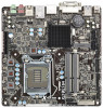
3W Audio AMP Output Wafer Header (4-pin SPEAKER1) (see p.14, No. 28) Power LED Header (3-pin PLED1) (see p.14, No. 11) Chassis Fan Connector (4-pin CHA_FAN1) (see p.14, No. 4) CPU Fan Connectors (4-pin CPU_FAN1) (see p.14, No. 22) Serial Port Header (10-pin COM1) (see p.14, No. 18) Please connect the chassis speaker to this header. Please connect the chassis power LED to this header to indicate system power status. The LED is on when the system is operating. The LED keeps blinking in S1/S3 state. The LED is off in S4 state or S5 state (power off). Please connect a fan cable to the fan connector and match the black wire to the ground pin. Though this motherboard provides a 4-Pin CPU fan (Quiet Fan) connector, 3-Pin CPU fans can still work even without fan speed control. If you plan to connect a 3-Pin CPU fan, please connect it to Pin 1-3. This COM1 header supports a serial port module. 28
-
 1
1 -
2
-
3
-
4
-
5
-
6
-
7
-
8
-
9
-
10
-
11
-
12
-
13
-
14
-
15
-
16
-
17
-
18
-
19
-
20
-
21
-
22
-
 23
23 -
 24
24 -
 25
25 -
 26
26 -
 27
27 -
 28
28 -
 29
29 -
 30
30 -
 31
31 -
 32
32 -
 33
33 -
34
-
35
-
36
-
37
-
38
-
39
-
40
-
41
-
42
-
43
-
44
-
45
-
46
-
47
-
48
-
49
-
50
-
51
-
52
-
53
-
54
-
55
-
56
-
57
-
58
-
59
-
60
-
61
-
62
-
63
-
64
-
65
-
66
-
67
-
68
 |
 |
