ASRock H81TM-ITX User Manual
ASRock H81TM-ITX Manual
 |
View all ASRock H81TM-ITX manuals
Add to My Manuals
Save this manual to your list of manuals |
ASRock H81TM-ITX manual content summary:
- ASRock H81TM-ITX | User Manual - Page 1
User Manual - ASRock H81TM-ITX | User Manual - Page 2
documentation are furnished for informational use only and subject to change without notice, and should not be constructed as a commitment by ASRock. ASRock assumes no responsibility for any errors or omissions that may appear in this documentation. With respect to the contents of this documentation - ASRock H81TM-ITX | User Manual - Page 3
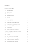
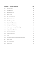
Headers and Connectors 21 Chapter 3 Software and Utilities Operation 26 3.1 Installing Drivers 26 3.2 A-Tuning 27 3.3 Intel® Smart Connect Technology 30 3.4 Intel® Remote Wake Technology 35 3.4.1 Configuring and Using MeshCentral 35 3.4.2 Configuring and Using Splashtop 40 3.5 Start8 - ASRock H81TM-ITX | User Manual - Page 4
48 4.3 OC Tweaker Screen 49 4.4 Advanced Screen 57 4.4.1 CPU Configuration 58 4.4.2 Chipset Configuration 60 4.4.3 Storage Configuration 63 4.4.4 Intel® Smart Connect Technology 64 4.4.5 Super IO Configuration 65 4.4.6 ACPI Configuration 66 4.4.7 USB Configuration 68 4.5 Tools 69 - ASRock H81TM-ITX | User Manual - Page 5
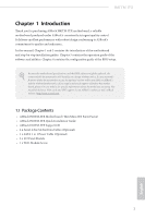
on ASRock's website as well. ASRock website http://www.asrock.com. 1.1 Package Contents • ASRock H81TM-ITX Motherboard (Thin Mini-ITX Form Factor) • ASRock H81TM-ITX Quick Installation Guide • ASRock H81TM-ITX Support CD • 2 x Serial ATA (SATA) Data Cables (Optional) • 1 x SATA 1 to 1 Power Cable - ASRock H81TM-ITX | User Manual - Page 6
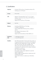
with Mini-ITX) • Solid Capacitor for CPU power A-Style • Home Cloud CPU Chipset • Supports 4th Generation Intel® CoreTM i7 / i5 / i3 / Xeon® / Pentium® / Celeron® processors with up to 65W TDP in an LGA1150 package • Supports Intel® Turbo Boost 2.0 Technology • Intel® H81 Memory • Dual - ASRock H81TM-ITX | User Manual - Page 7
H81TM-ITX • Supports LVDS with max. resolution up to 1920x1200 @ 60Hz • Supports Auto Lip Sync, Deep Color (12bpc), xvYCC and HBR (High Bit Rate Audio) with HDMI Port (Compliant HDMI monitor is required) • Supports HDCP function with HDMI • Supports Full HD 1080p Blu-ray (BD) playback with HDMI - ASRock H81TM-ITX | User Manual - Page 8
, CPU Vcore • Microsoft® Windows® 8.1 32-bit / 8.1 64-bit / 8 32-bit / 8 64bit / 7 32-bit / 7 64-bit Certifications • FCC, CE, WHQL • ErP/EuP Ready (ErP/EuP ready power supply is required) * For detailed product information, please visit our website: http://www.asrock.com English 4 - ASRock H81TM-ITX | User Manual - Page 9
H81TM-ITX Due to limitation, the actual memory size may be less than 4GB for the reservation for system usage under Windows® 32-bit operating systems. Windows® 64-bit operating systems do not have such limitations. You can use ASRock XFast RAM to utilize the memory that Windows® cannot use. 5 - ASRock H81TM-ITX | User Manual - Page 10
you to quickly charge many Apple devices simultaneously and even supports continuous charging when your PC enters into Standby mode (S1), Suspend to RAM (S3), hibernation mode (S4) or power off (S5). ASRock XFast LAN ASRock XFast LAN provides faster internet access, which includes the benefits - ASRock H81TM-ITX | User Manual - Page 11
H81TM-ITX ASRock Crashless BIOS ASRock Crashless BIOS allows users to update their BIOS without fear of failing. If power loss occurs during the BIOS updating process, ASRock Crashless BIOS will automatically finish the BIOS update procedure after regaining power. Please note that BIOS files need to - ASRock H81TM-ITX | User Manual - Page 12
the USB Key and let your computer log in to windows automatically! ASRock Home Cloud This motherboard supports remote wake with the onboard Intel LAN, so you can connect with your PC from anywhere in the world. You will be able to power your PC on or turn it off, monitor and take control - ASRock H81TM-ITX | User Manual - Page 13
H81TM-ITX 1.4 Motherboard Layout 12 3 45 6 7 8 HDMI1 MINI_PCIE1 24 DC Jack USB 3.0 T: USB0 B: USB1 LPC1 1 CMOS Battery 1 PLED1 CHA_FAN1 CIR1 1 1 USB4_5 SATA_1 SATA_0 DVI1 CLRCMOS1 1 23 Intel H81 22 21 20 19 RJ-45 LAN HTPC1 32Mb BIOS 1 USB 2.0 T: USB0 B: USB1 SPEAKER1 1 - ASRock H81TM-ITX | User Manual - Page 14
(CHA_FAN1) 4 Consumer Infrared Module Header (CIR1) 5 SATA3 Connector (SATA_0) 6 USB 2.0 Header (USB4_5) 7 SATA Power Connector (SATA_POW1) 8 System Panel Header (PANEL1) 9 Backlight Power Jumper (BKT_PWR1) 10 Panel Power Jumper (PNL_PWR1) 11 LVDS Connector (LVDS1) 12 2 x 204-pin DDR3 SO-DIMM Slots - ASRock H81TM-ITX | User Manual - Page 15
1.5 I/O Panel H81TM-ITX 1 2 3 4 5 6 78 No. Description 1 DC Jack* 2 USB 3.0 Ports (USB3_01) 3 DVI-I Port (DVI1) 4 HDMI Port (HDMI1) No. Description 5 LAN RJ-45 Port** 6 USB 2.0 Ports (USB01) 7 Microphone (Pink) 8 Front Speaker (Lime) * Please use a 19V power adapter for the DC jack. This - ASRock H81TM-ITX | User Manual - Page 16
Chapter 2 Installation This is a Thin Mini-ITX form factor motherboard. Before you install the motherboard, study install motherboard components or change any motherboard settings. • Make sure to unplug the power cord before installing or removing the motherboard. Failure to do so may cause physical - ASRock H81TM-ITX | User Manual - Page 17
H81TM-ITX 2.1 Installing the CPU 1. Before you insert the 1150-Pin CPU into the socket, please check if the PnP cap is insert the CPU into the socket if above situation is found. Otherwise, the CPU will be seriously damaged. 2. Unplug all power cables before installing the CPU. 1 A B 2 13 English - ASRock H81TM-ITX | User Manual - Page 18
4 5 14 3 English - ASRock H81TM-ITX | User Manual - Page 19
H81TM-ITX Please save and replace the cover if the processor is removed. The cover must be placed if you wish to return the motherboard for after service. 15 English - ASRock H81TM-ITX | User Manual - Page 20
2.2 Installing the CPU Fan and Heatsink 1 2 CPU_FAN English 16 - ASRock H81TM-ITX | User Manual - Page 21
H81TM-ITX 2.3 Installing Memory Modules (SO-DIMM) This motherboard provides two 204-pin DDR3 (Double Data Rate 3) SO-DIMM slots. It is not allowed to install a DDR - ASRock H81TM-ITX | User Manual - Page 22
1 2 18 English - ASRock H81TM-ITX | User Manual - Page 23
H81TM-ITX 2.4 Expansion Slots (PCI Express Slots) There is 1 PCI Express slot and 1 mini PCI Express slot on this motherboard. Before installing an expansion card, please make sure that the power supply is switched off or the power cord is unplugged. Please read the documentation of the expansion - ASRock H81TM-ITX | User Manual - Page 24
from the power supply. After waiting for 15 seconds, use a jumper cap to short pin2 and pin3 on CLRCMOS1 for 5 seconds. However, please do not clear the CMOS right after you update the BIOS. If you need to clear the CMOS when you just finish updating the BIOS, you must boot up the system - ASRock H81TM-ITX | User Manual - Page 25
H81TM-ITX 2.6 Onboard Headers and Connectors Onboard headers and connectors are NOT jumpers. Do NOT system is in S1/S3 sleep state. The LED is off when the system is in S4 sleep state or powered off (S5). HDLED (Hard Drive Activity LED): Connect to the hard drive activity LED on the chassis front - ASRock H81TM-ITX | User Manual - Page 26
MIC2_R to the front audio panel. MIC2_L 1 English 1. High Definition Audio supports Jack Sensing, but the panel wire on the chassis must support HDA to function correctly. Please follow the instructions in our manual and chassis manual to install your system. 2. If you use an AC'97 audio panel - ASRock H81TM-ITX | User Manual - Page 27
H81TM-ITX Analog Surround Audio Header (17-pin HD_AUDIO2) (see p.9, No. 20) Signal Signal PIN PIN Name Name 18 SENSE 17 KEY 16 LFE 15 A_GND 14 - ASRock H81TM-ITX | User Manual - Page 28
GND This header can be used to connect the remote controller receiver. RI RTS GND TXD DCD 1 NC CTS DSR DTR RXD This COM1 header supports a serial port module. PIN Signal Name PIN Signal Name 14 +3V 13 No pin 12 +3V 11 +3V 10 GND 9 GND 1 8 LAD3 7 LAD2 6 LAD1 5 LAD0 - ASRock H81TM-ITX | User Manual - Page 29
H81TM-ITX Home Theater PC Header (7-pin HTPC1) (see p.9, No. 22) PIN Signal Name PIN Signal Name 8 HDMI CEC 7 #Power_Button 6 SMB_DATA 5 3.3V Standby 1 4 SMB_CLK 3 No pin 2 GND 1 - ASRock H81TM-ITX | User Manual - Page 30
CD that comes with the motherboard contains necessary drivers and useful utilities that enhance the motherboard's features. Running The Support CD To begin using the support CD, insert the CD into your CD-ROM drive. The CD automatically displays the Main Menu if "AUTORUN" is enabled in your computer - ASRock H81TM-ITX | User Manual - Page 31
H81TM-ITX 3.2 A-Tuning A-Tuning is ASRock's multi A-Tuning When you install the all-in-one driver to your system from ASRock's support CD, A-Tuning will be auto-installed as well. After the installation, Info and Tech Service. Operation Mode Choose an operation mode for your computer. 27 English - ASRock H81TM-ITX | User Manual - Page 32
hidden partition, then assign which files should be stored in the RAM drive. Good Night LED Switch off the Power/HDD/LAN LEDs when the system is on, and automatically switch off the Power and Keyboard LEDs when the system enters into Standby/ Hibernation mode. FAN-Tastic Tuning Configure up to five - ASRock H81TM-ITX | User Manual - Page 33
OC Tweaker Configurations for overclocking the system. H81TM-ITX System Info View information about the system. Tech Service Contact Tech Service. 29 English - ASRock H81TM-ITX | User Manual - Page 34
Intel® Smart Connect Technology is a feature that periodically wakes your computer from Windows® sleep state to refresh email or social networking applications. It saves your waiting time and keeps the content always up-to-date. 3.3.1 System Requirements • Confirm whether your motherboard supports - ASRock H81TM-ITX | User Manual - Page 35
H81TM-ITX 3.3.2 Setup Guide Installing ASRock Smart Connect Utility Step 1 Install ASRock Smart Connect Utility, which is located in the folder at the following path of the Support CD: \ ASRock Utility > Smart Connect. Step 2 Once installed, run ASRock Smart Connect from your desktop or go to - ASRock H81TM-ITX | User Manual - Page 36
Step 3 Click the Add button. Take Foxmail as an example, add Foxmail to the Application list. Step 4 Select Foxmail from the Application List, then click the arrow pointing right to add this application to the Smart Connect List. Step 5 Click Apply to enable Smart Connect. 32 English - ASRock H81TM-ITX | User Manual - Page 37
H81TM-ITX Step 6 Double-click the Intel® Smart Connect Technology Manager icon Windows system tray. in the Step 7 Drag the slider to configure how often the system will connect to the network to download updates. Shorter durations will provide more frequent updates, but may cause more power - ASRock H81TM-ITX | User Manual - Page 38
wake up from sleep state periodically, and then start to update Foxmail. The screen will not display anything so the computer can maintain minimum power usage. Afterwards, the system will automatically return to sleep state again. 5. Upon waking up the system, you will find the new mail that were - ASRock H81TM-ITX | User Manual - Page 39
H81TM-ITX 3.4 Intel® Remote Wake Technology Intel® Remote Wake Technology allows you to use programs or services over the Internet to wake up your home computer from energy efficient sleep mode. Before configuring this feature, verify the following. • Remote Wake has been enabled in "Intel® Smart - ASRock H81TM-ITX | User Manual - Page 40
Step 3 A new mesh window will pop up. Enter a mesh name and password. Step 4 Select all the checkboxes and click Create Mesh. Downloading and Installing Mesh Agent Step 1 Click Install on the My Account page. Step 2 Select the mesh and download both files. Make sure both files are in the same - ASRock H81TM-ITX | User Manual - Page 41
Step 4 Click Install / Update. H81TM-ITX Step 5 Wait a minute for the New Machine to appear in "My Device". English 37 - ASRock H81TM-ITX | User Manual - Page 42
Step 6 Check whether "Intel Remote Wake" appeared or not. Waking up Your PC using PC Step 1 On the "My Devices" page, click on Power Actions. Step 2 Click on Wake or Sleep. 38 English - ASRock H81TM-ITX | User Manual - Page 43
H81TM-ITX Waking up Your PC Using Mobile Device Before waking up your home computer using a mobile device, please log out of MeshCentral on other previously used - ASRock H81TM-ITX | User Manual - Page 44
agent. • Remote Wake has been enabled in "Intel® Smart Connect Technology Manager". Setup Guide Step 1 Download and install the Streamer on your home computer, which is located in the folder at the following path of the Support CD: \ ASRock Utility > Splashtop Streamer. Then enter your Splashtop - ASRock H81TM-ITX | User Manual - Page 45
H81TM-ITX Using Remote Control Step 1 In "Splashtop 2", tap an online machine from the list to connect to your home computer. Step 2 Start remotely accessing your home computer. The functionality and price of the Splashtop APP and subscription fee is subject to change. Please check www.splashtop.com - ASRock H81TM-ITX | User Manual - Page 46
Accessing Data Playing Video 42 English - ASRock H81TM-ITX | User Manual - Page 47
H81TM-ITX 3.5 Start8 For those Windows 8 users who miss the Start Menu, Start8 is Installing Start8 Install Start8, which is located in the folder at the following path of the Support CD: \ ASRock Utility > Start8. 3.5.2 Configuring Start8 Style Select between the Windows 7 style and Windows 8 - ASRock H81TM-ITX | User Manual - Page 48
Configure Configure provides configuration options, including icon sizes, which shortcuts you want Start Menu to display, quick access to recently used apps, the functionality of the power button, and more. Control 44 English - ASRock H81TM-ITX | User Manual - Page 49
H81TM-ITX Control lets you configure what a click on the start button or a press on the Windows key does. Desktop Desktop allows you to disable the hot - ASRock H81TM-ITX | User Manual - Page 50
Chapter 4 UEFI SETUP UTILITY 4.1 Introduction ASRock Interactive UEFI is a blend of system configuration tools, cool sound effects and stunning visuals. Not only will it make BIOS setup less difficult but also a lot more amusing. This section explains how to use the UEFI Setup Utility to configure - ASRock H81TM-ITX | User Manual - Page 51
H81TM-ITX 4.1.2 Navigation Keys Use < > key or < > key to choose among the selections on the menu bar, and use < > key or < > key to move the cursor up - ASRock H81TM-ITX | User Manual - Page 52
, the Main screen will appear and display the system overview. Active Page on Entry Select the default page when entering the UEFI setup utility. UEFI Guide UEFI Guide is a quick tutorial for ASRock's UEFI setup Utility. You may abort the tutorial by pressing "esc". 48 English - ASRock H81TM-ITX | User Manual - Page 53
OC Tweaker screen, you can set up overclocking features. H81TM-ITX Because the UEFI software is constantly being updated, the perform the highest frequency on all CPU cores simultaneously. Disable to reduce power consumption. CPU Configuration CPU Ratio The CPU speed is determined by the CPU - ASRock H81TM-ITX | User Manual - Page 54
SpeedStep technology allows processors to switch between multiple frequencies and voltage points for better power saving and heat dissipation. Intel Turbo Boost Technology Intel Turbo Boost Technology enables the processor to run above its base operating frequency when the operating system requests - ASRock H81TM-ITX | User Manual - Page 55
H81TM-ITX GT Frequency Configure the frequency of the integrated GPU. GT Voltage Mode Auto: For optimized settings. Adaptive: Add voltage to the integrated GPU when the - ASRock H81TM-ITX | User Manual - Page 56
DRAM Configuration CAS# Latency (tCL) The time between sending a column address to the memory and the beginning of the data in response. RAS# to CAS# Delay (tRCD) The number of clock cycles required between the opening of a row of memory and accessing columns within it. Row Precharge Time (tRP) The - ASRock H81TM-ITX | User Manual - Page 57
H81TM-ITX Write Recovery Time (tWR) The amount of delay that must elapse after the completion of a valid write operation, before an active bank can be precharged. - ASRock H81TM-ITX | User Manual - Page 58
write to read delay. tWRRDDR Configure between module write to read delay from different ranks. tWRRDDD Use this to change DRAM tRRSR Auto/Manual settings. The default is [Auto]. Configure between module write to read delay from different DIMMs. tWRWR Configure between module write to write delay - ASRock H81TM-ITX | User Manual - Page 59
H81TM-ITX ODT NOM (CHA) Use this to change ODT (CHA) Auto/Manual settings. The default is [Auto]. ODT NOM (CHB) Use this to change ODT (CHB) Auto/Manual settings. The default is [Auto]. Command Tri State Enable for DRAM power saving. MRC Fast Boot Enable Memory Fast Boot to skip DRAM memory training - ASRock H81TM-ITX | User Manual - Page 60
. CPU Integrated VR Efficiency Mode Enable FIVR Efficiency Management for power saving. Disable for better performance and overclocking capabilities. Voltage Configuration Power Saving Mode Enable Power Saving Mode to reduce power consumption. DRAM Voltage Use this to configure DRAM Voltage. The - ASRock H81TM-ITX | User Manual - Page 61
H81TM-ITX 4.4 Advanced Screen In this section, you may set the configurations for the following items: CPU Configuration, Chipset Configuration, Storage Configuration, Intel® Smart Connect Technology, Super IO Configuration, ACPI Configuration and USB Configuration. Setting wrong values in this - ASRock H81TM-ITX | User Manual - Page 62
. Enhanced Halt State (C1E) Enable Enhanced Halt State (C1E) for lower power consumption. CPU C3 State Support Enable C3 sleep state for lower power consumption. CPU C6 State Support Enable C6 deep sleep state for lower power consumption. CPU C7 State Support Enable C7 deep sleep state for lower - ASRock H81TM-ITX | User Manual - Page 63
H81TM-ITX Package C State Support Enable CPU, PCIe, Memory, Graphics C State Support for power saving. CPU Thermal Throttling Enable CPU internal certain classes of malicious buffer overflow attacks. Intel Virtualization Technology Intel Virtualization Technology allows a platform to run multiple - ASRock H81TM-ITX | User Manual - Page 64
4.4.2 Chipset Configuration Primary Graphics Adapter Select a primary VGA. VT-d Intel® Virtualization Technology for Directed I/O helps your virtual machine monitor better utilize hardware by improving application compatibility and reliability, and providing additional levels of manageability, - ASRock H81TM-ITX | User Manual - Page 65
H81TM-ITX Render Standby Power down the render unit when the GPU is idle for lower power consumption. LVDS Configuration This allows you to enable or disable the Onboard LVDS. Panel Type Selection Use this to select a panel type. Primary IGFX Boot Display - ASRock H81TM-ITX | User Manual - Page 66
Restore on AC/Power Loss Select the power state after a power failure. If [Power Off] is selected, the power will remain off when the power recovers. If [Power On] is selected, the system will start to boot up when the power recovers. Good Night LED By enabling Good Night LED, the Power/HDD LEDs - ASRock H81TM-ITX | User Manual - Page 67
4.4.3 Storage Configuration H81TM-ITX SATA Controller(s) Enable/disable the SATA controllers. SATA Mode Selection IDE: For better compatibility. AHCI: Supports new features that improve performance. AHCI (Advanced Host Controller Interface) supports NCQ and other new features that will improve - ASRock H81TM-ITX | User Manual - Page 68
4.4.4 Intel® Smart Connect Technology Intel® Smart Connect Technology Intel® Smart Connect Technology automatically updates your email and social networks, such as Twitter, Facebook, etc. while the computer is in sleep mode. 64 English - ASRock H81TM-ITX | User Manual - Page 69
4.4.5 Super IO Configuration H81TM-ITX Serial Port Enable or disable the Serial port. Serial Port Address Select the address of the Serial port. 65 English - ASRock H81TM-ITX | User Manual - Page 70
High Precision Event Timer for better performance and to pass WHQL tests. PCIE Devices Power On Allow the system to be waked up by a PCIE device and enable wake Allow the system to be waked up by the Onboard Intel I217V LAN. Ring-In Power On Allow the system to be waked up by onboard COM port - ASRock H81TM-ITX | User Manual - Page 71
H81TM-ITX RTC Alarm Power On Allow the system to be waked up by the real time clock alarm. Set it to By OS to let it be handled by your operating system. USB Keyboard/Remote Power On Allow the system to be waked up by an USB keyboard or remote controller. USB Mouse Power On - ASRock H81TM-ITX | User Manual - Page 72
4.4.7 USB Configuration USB Controller Enable or disable all the USB ports. USB 3.0 Controller Enable or disable all the USB 3.0 ports. Legacy USB Support Enable or disable Legacy OS Support for USB 2.0 devices. If you encounter USB compatibility issues it is recommended to disable legacy USB - ASRock H81TM-ITX | User Manual - Page 73
H81TM-ITX UEFI Tech Service Contact ASRock Tech Service if you are having trouble with your PC. Please setup network configuration before using UEFI Tech Service. Easy Driver Installer For users that don't have an optical disk drive to install the drivers from our support Flash ASRock Internet - ASRock H81TM-ITX | User Manual - Page 74
utility. UEFI Download Server Select a server to download the UEFI firmware. Dehumidifier Function If Dehumidifier Function is enabled, the computer will power on automatically to dehumidify the system after entering S4/S5 state. Dehumidifier Period Configure the period of time until the computer - ASRock H81TM-ITX | User Manual - Page 75
H81TM-ITX Dehumidifier CPU Fan Setting Configure the speed of the CPU fan while Dehumidifier is enabled. The higher the value, the faster the fan speed. Max: - ASRock H81TM-ITX | User Manual - Page 76
4.6 Hardware Health Event Monitoring Screen This section allows you to monitor the status of the hardware on your system, including the parameters of the CPU temperature, motherboard temperature, fan speed and voltage. CPU Fan 1 Setting Select a fan mode for CPU Fans 1, or choose Customize to set 5 - ASRock H81TM-ITX | User Manual - Page 77
H81TM-ITX 4.7 Boot Screen This section displays the available devices on your system for you to configure the boot settings and the boot priority. Fast Boot Fast Boot minimizes your computer's boot time. In fast mode you may not boot from an USB storage device. Ultra Fast mode is only supported by - ASRock H81TM-ITX | User Manual - Page 78
Guard Count Configure the number of attempts to boot until the system automatically restores the default settings. CSM (Compatibility Support Module) CSM Enable to launch the Compatibility Support Module. Please do not disable unless you're running a WHCK test. If you are using Windows 8 64-bit and - ASRock H81TM-ITX | User Manual - Page 79
H81TM-ITX Launch PXE OpROM Policy Select UEFI only to run those that support UEFI option ROM only. Select Legacy only to run those that support legacy option ROM only. Do not launch? Launch Storage OpROM Policy Select UEFI only to run those that support UEFI option ROM only. Select Legacy only to - ASRock H81TM-ITX | User Manual - Page 80
are unable to change the settings in the UEFI Setup Utility. Leave it blank and press enter to remove the password. Secure Boot Enable to support Windows 8 Secure Boot. 76 English - ASRock H81TM-ITX | User Manual - Page 81
4.9 Exit Screen H81TM-ITX Save Changes and Exit When you select this option the following message, "Save configuration changes and exit setup?" will pop out. Select [OK] to save - ASRock H81TM-ITX | User Manual - Page 82
or want to know more about ASRock, you're welcome to visit ASRock's website at http://www.asrock.com; or you may contact your dealer for further information. For technical questions, please submit a support request form at http://www.asrock.com/support/tsd.asp ASRock Incorporation 2F., No.37, Sec
-
 1
1 -
 2
2 -
 3
3 -
 4
4 -
 5
5 -
 6
6 -
 7
7 -
8
-
9
-
10
-
11
-
12
-
13
-
14
-
15
-
16
-
17
-
18
-
19
-
20
-
21
-
22
-
23
-
24
-
25
-
26
-
27
-
28
-
29
-
30
-
31
-
32
-
33
-
34
-
35
-
36
-
37
-
38
-
39
-
40
-
41
-
42
-
43
-
44
-
45
-
46
-
47
-
48
-
49
-
50
-
51
-
52
-
53
-
54
-
55
-
56
-
57
-
58
-
59
-
60
-
61
-
62
-
63
-
64
-
65
-
66
-
67
-
68
-
69
-
70
-
71
-
72
-
73
-
74
-
75
-
76
-
77
-
78
-
79
-
80
-
81
-
82
 |
 |
User Manual