ASRock H81TM-ITX Quick Installation Guide - Page 24
Signal
 |
View all ASRock H81TM-ITX manuals
Add to My Manuals
Save this manual to your list of manuals |
Page 24 highlights
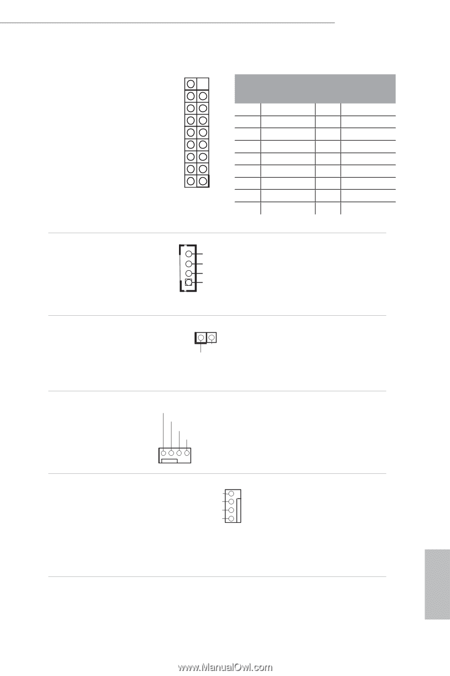
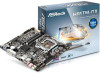
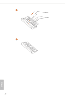
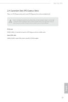
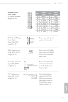
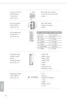
H81TM-ITX Analog Surround Audio Header (17-pin HD_AUDIO2) (see p.1, No. 20) Signal Signal PIN PIN Name Name 18 SENSE 17 KEY 16 LFE 15 A_GND 14 A_GND 13 Center 12 Surr_Rear_R 11 A_GND 10 A_GND 9 Surr_Rear_L 8 Surr_Side_R 7 A_GND 2 1 6 A_GND 5 Surr_Side_L 4 Front_R 3 A_GND 2 A_GND 1 Front_L 3W Audio AMP Output Wafer Header (4-pin SPEAKER1) (see p.1, No. 21) Front_RFront_R+ Front_L+ Front_L- 1 Please connect the chassis speaker to this header. SPDIF Out Connector (2-pin SPDIF_OUT1) (see p.1, No. 18) 1 GND SPDIFOUT Please connect the SPDIF Out connector of a HDMI VGA card to this header with a cable. Chassis Fan Connector (4-pin CHA_FAN1) (see p.1, No. 3) GND +12V CHA_FAN_SPEED FAN_SPEED_CONTROL Please connect fan cable to the fan connector and match the black wire to the ground pin. CPU Fan Connector (4-pin CPU_FAN1) (see p.1, No. 16) FAN_SPEED_CONTROL FAN_SPEED + 12V GN D 4 This motherboard pro3 vides a 4-Pin CPU fan 2 1 (Quiet Fan) connector. If you plan to connect a 3-Pin CPU fan, please connect it to Pin 1-3. English 23
-
 1
1 -
2
-
3
-
4
-
5
-
6
-
7
-
8
-
9
-
10
-
11
-
12
-
13
-
14
-
15
-
16
-
17
-
18
-
 19
19 -
 20
20 -
 21
21 -
 22
22 -
 23
23 -
 24
24 -
 25
25 -
 26
26 -
 27
27 -
 28
28 -
 29
29 -
30
-
31
-
32
-
33
-
34
-
35
-
36
-
37
-
38
-
39
-
40
-
41
-
42
-
43
-
44
-
45
-
46
-
47
-
48
-
49
-
50
-
51
-
52
-
53
-
54
-
55
-
56
-
57
-
58
-
59
-
60
-
61
-
62
-
63
-
64
-
65
-
66
-
67
-
68
-
69
-
70
-
71
-
72
-
73
-
74
-
75
-
76
-
77
-
78
-
79
-
80
-
81
-
82
-
83
-
84
-
85
-
86
-
87
-
88
-
89
-
90
-
91
-
92
-
93
-
94
-
95
-
96
-
97
-
98
-
99
-
100
-
101
-
102
-
103
-
104
-
105
-
106
-
107
-
108
-
109
-
110
-
111
-
112
-
113
-
114
-
115
-
116
-
117
-
118
-
119
-
120
-
121
-
122
-
123
-
124
-
125
-
126
-
127
-
128
-
129
-
130
-
131
-
132
-
133
-
134
-
135
-
136
-
137
-
138
-
139
-
140
-
141
-
142
-
143
-
144
-
145
-
146
-
147
-
148
-
149
-
150
-
151
-
152
-
153
-
154
-
155
-
156
-
157
-
158
-
159
 |
 |