ASRock H91M-S User Guide - Page 24
CPU Fan Connector, pin CHA_FAN1 - s1
 |
View all ASRock H91M-S manuals
Add to My Manuals
Save this manual to your list of manuals |
Page 24 highlights
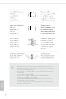
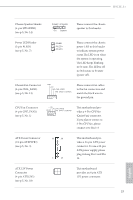
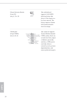
H91M-S+ Chassis Speaker Header (4-pin SPEAKER1) (see p.5, No. 14) DUMMY SPEAKER 1 +5V DUMMY Please connect the chassis speaker to this header. Power LED Header (3-pin PLED1) (see p.5, No. 7) PLEDPLED+ PLED+ 1 Please connect the chassis power LED to this header to indicate system power status.The LED is on when the system is operating. The LED keeps blinking in S1 state. The LED is off in S3/S4 state or S5 state (power off). Chassis Fan Connector (4-pin CHA_FAN1) (see p.5, No. 13) GND +12V CHA_FAN_SPEED FAN_SPEED_CONTROL Please connect fan cables to the fan connectors and match the black wire to the ground pin. CPU Fan Connector (4-pin CPU_FAN1) (see p.5, No. 1) +12V CPU_FAN_SPEED GND FAN_SPEED_CONTROL This motherboard provides a 4-Pin CPU fan (Quiet Fan) connector. If you plan to connect a 3-Pin CPU fan, please connect it to Pin 1-3. ATX Power Connector (24-pin ATXPWR1) (see p.5, No. 3) 12 24 1 13 This motherboard provides a 24-pin ATX power connector. To use a 20-pin ATX power supply, please plug it along Pin 1 and Pin 13. ATX 12V Power Connector (4-pin ATX12V1) (see p.5, No. 18) This motherboard provides an 4-pin ATX 12V power connector. 19 English
-
 1
1 -
2
-
3
-
4
-
5
-
6
-
7
-
8
-
9
-
10
-
11
-
12
-
13
-
14
-
15
-
16
-
17
-
18
-
 19
19 -
 20
20 -
 21
21 -
 22
22 -
 23
23 -
 24
24 -
 25
25 -
 26
26 -
 27
27 -
 28
28 -
 29
29 -
30
-
31
-
32
-
33
-
34
-
35
-
36
-
37
-
38
-
39
-
40
-
41
-
42
-
43
-
44
-
45
-
46
-
47
-
48
-
49
-
50
-
51
-
52
-
53
-
54
-
55
-
56
-
57
-
58
-
59
-
60
-
61
-
62
-
63
-
64
-
65
-
66
-
67
-
68
-
69
-
70
-
71
-
72
-
73
-
74
-
75
-
76
-
77
-
78
-
79
 |
 |
