ASRock K10N78-1394 User Manual
ASRock K10N78-1394 Manual
 |
View all ASRock K10N78-1394 manuals
Add to My Manuals
Save this manual to your list of manuals |
ASRock K10N78-1394 manual content summary:
- ASRock K10N78-1394 | User Manual - Page 1
K10N78-1394 / K10N78 User Manual Version 1.1 Published August 2008 Copyright©2008 ASRock INC. All rights reserved. 1 - ASRock K10N78-1394 | User Manual - Page 2
purchaser for backup purpose, without written consent of ASRock Inc. Products and corporate names appearing in this manual may or may not be registered trademarks or copyrights USA ONLY The Lithium battery adopted on this motherboard contains Perchlorate, a toxic substance controlled in Perchlorate - ASRock K10N78-1394 | User Manual - Page 3
Support 11 1.4 Passed 1080p Blu-ray (BD) / HD-DVD Films in Our Lab Test ... 12 1.5 Motherboard Layout (K10N78-1394 13 1.6 Motherboard Layout (K10N78 14 1.7 I/O Panel (K10N78-1394 15 1.8 I/O Panel (K10N78 and Operation Guide ..... 44 2.16 Driver Installation Guide 46 2.17 Installing Windows® XP - ASRock K10N78-1394 | User Manual - Page 4
Windows® VistaTM / VistaTM 64-bit With RAID Functions 49 2.19 Untied Overclocking Technology 50 3 . BIOS SETUP UTILITY 51 3.1 Introduction 51 3.1.1 BIOS 4 . Software Support 72 4.1 Install Operating System 72 4.2 Support CD Information 72 4.2.1 Running Support CD 72 4.2.2 Drivers Menu 72 - ASRock K10N78-1394 | User Manual - Page 5
www.asrock.com/support/index.asp 1.1 Package Contents ASRock K10N78-1394 / K10N78 Motherboard (ATX Form Factor: 12.0-in x 8.4-in, 30.5 cm x 21.3 cm) ASRock K10N78-1394 / K10N78 Quick Installation Guide ASRock K10N78-1394 / K10N78 Support CD One 80-conductor Ultra ATA 66/100/133 IDE Ribbon Cable One - ASRock K10N78-1394 | User Manual - Page 6
(K10N78-1394) - Support for Socket AM2+ / AM2 processors: AMD support DVI-D and D-Sub ports by independent display controllers - Supports HDCP function with DVI-D port - Supports 1080p Blu-ray (BD) / HD-DVD playback with DVI-D port (see CAUTION 8) - NVIDIA® PureVideoTM HD Ready - 7.1 CH Windows - ASRock K10N78-1394 | User Manual - Page 7
Connector BIOS Feature Support CD I/O Panel - 1 x PS/2 Mouse Port - 1 x PS/2 Keyboard Port - 1 x VGA/D-Sub Port - 1 x VGA/DVI-D Port - 6 x Ready-to-Use USB 2.0 Ports - 1 x eSATAII Port (K10N78-1394) - 1 x RJ-45 LAN Port with LED (ACT/LINK LED and SPEED LED) - 1 x IEEE 1394 Port (K10N78-1394) - HD - ASRock K10N78-1394 | User Manual - Page 8
+5V, +3.3V, CPU Vcore OS - Microsoft® Windows® XP / XP Media Center / XP 64-bit the setting in the BIOS, applying Untied Overclocking AM2+ CPU you adopt. Please refer to the CPU support list on our website for more information. ASRock website http://www.asrock.com 2. This motherboard supports - ASRock K10N78-1394 | User Manual - Page 9
SATAII connector, please read the "SATAII Hard Disk Setup Guide" on page 41 to adjust your SATAII hard disk drive to SATAII mode. You can also connect SATA hard disk to SATAII connector directly. 11. This motherboard supports eSATAII interface, the external SATAII specification. Please read "eSATAII - ASRock K10N78-1394 | User Manual - Page 10
thermal grease between the CPU and the heatsink when you install the PC system. 18. This motherboard supports ASRock AM2 Boost overclocking technology for AM2 CPU. If you enable this function in the BIOS setup, the memory performance will improve up to 12.5%, but the effect still depends on the - ASRock K10N78-1394 | User Manual - Page 11
/ HD-DVD playback is only supported under Windows® VistaTM / VistaTM 64-bit OS. If you install Windows® XP / XP 64-bit OS, the function of 1080p Blu-ray (BD) / HD-DVD playback is not available, please visit our website for NVIDIA® driver update in the future. ASRock website http://www.asrock.com 11 - ASRock K10N78-1394 | User Manual - Page 12
same format of H.264. * Above passed films are tested under below configuration. Items Configurations CPU AMD Phenom X3 8400 VGA Onboard VGA with DVI-D port Memory Dual Channel DDR2 533, 1GB x 2 OS Windows® VistaTM or Windows® VistaTM 64 Playback Software CyberLink PowerDVD Ultra DVD - ASRock K10N78-1394 | User Manual - Page 13
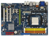
Motherboard Layout (K10N78-1394) 12 3 45 67 21.3cm (8.4-in) 1 PS2_USB_PW1 PS2 Mouse PS2 Keyboard AM2 SATAII_6 (PORT5), Orange) 30 Front Panel IEEE 1394 Header 12 SATAII Connector (SATAII_4 (PORT3 (PORT0), Red) 34 Serial Port Connector (COM1) 17 SPI BIOS Chip 35 ATX Power Connector (ATXPWR1 - ASRock K10N78-1394 | User Manual - Page 14
Motherboard Layout (K10N78) 12 3 45 21.3cm (8.4-in) 1 PS2_USB_PW1 67 PS2 Mouse PS2 Keyboard AM2+ FSB2.6GHz DVI_CON1 VGA1 USB 2.0 T: USB4 B: USB5 USB 2.0 T: USB2 B: USB3 USB 2.0 T: USB0 B: USB1 Top: RJ-45 ATX12V1 SOCKET AM2 BIOS Port Connector (COM1) 34 ATX Power Connector (ATXPWR1) 14 - ASRock K10N78-1394 | User Manual - Page 15
K10N78-1394) 1 2 34 5 6 9 7 10 8 11 16 15 14 1 PS/2 Mouse Port (Green) 2 VGA/D-Sub Port 3 USB 2.0 Ports (USB45) 4 IEEE 1394 Port * 5 LAN RJ-45 Port To enable Multi-Streaming function, you need to connect a front panel audio cable to the front panel audio header. After restarting your - ASRock K10N78-1394 | User Manual - Page 16
connection Blinking Data Activity Orange 100Mbps connection Green 1Gbps connection LAN Port ** If you use 2-channel speaker, please connect V V V To enable Multi-Streaming function, you need to connect a front panel audio cable to the front panel audio header. After restarting your computer, - ASRock K10N78-1394 | User Manual - Page 17
the power is switched off or the power cord is detached from the power supply. Failure to do so may cause severe damage to the motherboard, peripherals, and/or components. 1. Unplug the power cord from the wall socket before touching any component. 2. To avoid damaging the - ASRock K10N78-1394 | User Manual - Page 18
of CPU Fan and Heatsink After you install the CPU into this motherboard, it is necessary to install a larger heatsink and cooling fan to Then connect the CPU fan to the CPU FAN connector (CPU_FAN1, see Page 13/14, No. 3). For proper installation, please kindly refer to the instruction manuals of - ASRock K10N78-1394 | User Manual - Page 19
2.3 Installation of Memory Modules (DIMM) This motherboard provides four 240-pin DDR2 (Double Data Rate 2) DIMM slots, and supports Dual Channel Memory Technology. For dual channel configuration, you always need to install identical (the same brand, speed, size and chip-type) DDR2 DIMM pair - ASRock K10N78-1394 | User Manual - Page 20
matches the break on the slot. notch break notch break The DIMM only fits in one correct orientation. It will cause permanent damage to the motherboard and the DIMM if you force the DIMM into the slot at incorrect orientation. Step 3. Firmly insert the DIMM into the slot until the retaining - ASRock K10N78-1394 | User Manual - Page 21
the expansion card and make necessary hardware settings for the card before you start the installation. Step 2. Remove the system unit cover (if your motherboard is already installed in a chassis). Step 3. Remove the bracket facing the slot that you intend to use. Keep the screws for later use. Step - ASRock K10N78-1394 | User Manual - Page 22
SLITM Technology is only supported with Windows® VistaTM OS, and is not available with other OS. Please visit our website for the driver update in the future. GeForce® Boost GeForce® Boost turbocharges the performance of NVIDIA® discrete GPU when combined with NVIDIA® motherboard GPU. When GeForce - ASRock K10N78-1394 | User Manual - Page 23
Model Driver ASUS PCIE-ASUS-9800GX2/512M 174.83 Enjoy the benefit of NVIDIA® Hybrid SLITM To enjoy Hybrid SLITM feature, please refer to below installation and setup procedures according to the mode you plan to use. For users using single monitor: If you connect the monitor to the motherboard GPU - ASRock K10N78-1394 | User Manual - Page 24
. Step 5. Connect the monitor cable to the correspondent connector on the I/O shield. Step 6. Boot into OS. Install Hybrid SLITM driver from our support CD to your system. Hybrid SLITM driver is in the following path of ASRock support CD: (There are two ASRock support CD in the motherboard gift box - ASRock K10N78-1394 | User Manual - Page 25
of ASRock support CD: (There are two ASRock support CD in the motherboard gift box pack, please choose the one for Windows® VistaTM / VistaTM 64-bit.) ..\Drivers\Hybrid SLI driver\Vista * Currently, Hybrid SLITM driver only has VistaTM 32 version, please visit our website for future update. Step - ASRock K10N78-1394 | User Manual - Page 26
the below steps: 1. Connect the DVI-D monitor cable to the VGA/DVI-D port on the I/O panel of this motherboard. Connect the D-Sub monitor cable to the VGA/D-Sub port on the I/O panel of this motherboard. VGA/D-Sub port VGA/DVI-D port 2. If you have installed onboard VGA driver from our support CD to - ASRock K10N78-1394 | User Manual - Page 27
installation procedures for details. 2. Connect the DVI-D monitor cable to the VGA/DVI-D port on the I/O panel of this motherboard. Connect the D-Sub monitor cable to the VGA/D-Sub port on the I/O panel of this motherboard. 3. Boot your system. Press to enter BIOS setup. Enter "Share Memory - ASRock K10N78-1394 | User Manual - Page 28
is supported with DVI-D port on this motherboard. To use HDCP function with this motherboard, you need to adopt the monitor that supports HDCP function as well. Therefore, you can enjoy the superior display quality with high-definition HDCP encryption contents. Please refer to below instruction for - ASRock K10N78-1394 | User Manual - Page 29
sometimes. For Windows® XP / XP 64-bit OS Step 1: Set up BIOS. A. Enter BIOS SETUP UTILITY Advanced screen Chipset Configuration. B. Set the option "OnBoard HDMI HD Audio" to [Auto]. Step 2: Install HDMI audio driver to your system. Install "Onboard HDMI HD Audio Driver" from ASRock Support CD to - ASRock K10N78-1394 | User Manual - Page 30
short pin2 and pin3 on CLRCMOS1 for 5 seconds. However, please do not clear the CMOS right after you update the BIOS. If you need to clear the CMOS when you just finish updating the BIOS, you must boot up the system first, and then shut it down before you do the clear-CMOS action - ASRock K10N78-1394 | User Manual - Page 31
SATAII) connectors support SATA data cables for internal storage devices. The current SATAII interface allows up to 3.0 Gb/s data transfer rate. For K10N78-1394, SATAII_6 (PORT5) connector can be used for internal storage device or be connected to eSATAII connector to support eSATAII device. Please - ASRock K10N78-1394 | User Manual - Page 32
eSATAII connector supports SATA data cable for external SATAII function. The current eSATAII interface allows up to 3.0 Gb/s data transfer rate. Either end of the SATA data cable can be connected to the SATA / SATAII hard disk or the SATAII connector on this motherboard. For K10N78-1394, you can - ASRock K10N78-1394 | User Manual - Page 33
front panel audio cable that allows convenient connection and control of audio devices. 1. High Definition Audio supports Jack Sensing, but the panel wire on the chassis must support HDA to function correctly. Please follow the instruction in our manual and chassis manual to install your system - ASRock K10N78-1394 | User Manual - Page 34
, please deselect "Mute" icon in "Front Mic" of "Playback" portion. For Windows® VistaTM / VistaTM 64-bit OS: Go to the "Front Mic" Tab in the connect the CPU fan cable to this connector and match the black wire to the ground pin. Though this motherboard provides 4-Pin CPU fan (Quiet Fan) support, - ASRock K10N78-1394 | User Manual - Page 35
is one IEEE 1394 header (FRONT_1394) on this motherboard. This IEEE 1394 header can support one IEEE 1394 port. i HDMI_SPDIF Header HDMI_SPDIF header, providing (3-pin HDMI_SPDIF1) (see p.13/14, No. 29) 1 GND SPDIFOUT +5V SPDIF audio output to HDMI VGA card, allows the system to connect HDMI - ASRock K10N78-1394 | User Manual - Page 36
the black end (A) of HDMI_SPDIF cable to the HDMI_SPDIF header on the motherboard. Then connect the white end (B or C) of HDMI_SPDIF cable to the HDMI_SPDIF connector of HDMI VGA card. A. black end +5V SPDIFOUT GND B. white end (2-pin) C. white end (3-pin) blue black SPDIFOUT GND blue black - ASRock K10N78-1394 | User Manual - Page 37
connectors on HDMI VGA card, please refer to the user manual of HDMI VGA card vendor. Incorrect connection may cause permanent damage to this motherboard and the HDMI VGA card. Step 3. Connect the white end (B or C) of HDMI_SPDIF cable to the HDMI_SPDIF connector of HDMI VGA card. (There are - ASRock K10N78-1394 | User Manual - Page 38
K10N78-1394) What is eSATAII? This motherboard supports eSATAII hard disk to the eSATAII ports instead of opening your chassis to exchange IEEE 1394 to be a trend for external interface. NOTE: 1. If you set "SATA Operation Mode" option in BIOS setup to AHCI or RAID mode, Hot Plug function is supported - ASRock K10N78-1394 | User Manual - Page 39
connector (eSATAII_TOP) 2. Use the eSATAII device cable to connect eSATAII device and the eSATAII port of the I/O shield according to the eSATAII connector that you connect the SATA data cable. Connect one end of the eSATAII device cable to eSATAII device Connect the other end of the eSATAII - ASRock K10N78-1394 | User Manual - Page 40
Comparison between eSATAII and other devices IEEE 1394 USB 2.0 SATA eSATAII/SATAII 400Mb/s 480Mb/s 1.5Gb/s (1500Mb/s) 3.0Gb/s (3000Mb/s) 40 - ASRock K10N78-1394 | User Manual - Page 41
guide. Some default setting of SATAII hard disks may not be at SATAII mode, which operate with the best performance. In order to enable SATAII function, please follow the below instruction 's website for details: http://www.hitachigst.com/hdd/support/download.htm The above examples are just for your - ASRock K10N78-1394 | User Manual - Page 42
section will guide you to install the SATA / SATAII hard disks. STEP 1: Install the SATA / SATAII hard disks into the drive bays of your chassis. STEP 2: Connect the SATA power cable to the SATA / SATAII hard disk. STEP 3: Connect one end of the SATA data cable to the motherboard's SATAII connector - ASRock K10N78-1394 | User Manual - Page 43
motherboard supports Hot Plug and Hot Swap functions for SATA / SATAII / eSATAII Devices in RAID / AHCI mode. NVIDIA® GeForce 8200 chipset provides hardware support the system is still power-on and in working condition. For K10N78-1394, eSATAII is equipped with Hot Plug capability that enables you to - ASRock K10N78-1394 | User Manual - Page 44
is installed into system properly. The latest SATA / SATAII driver is available on our support website: www.asrock.com 4. Make sure to use the SATA power cable & data cable, which are from our motherboard package. 5. Please follow below instructions step by step to reduce the risk of HDD crash or - ASRock K10N78-1394 | User Manual - Page 45
follow below instruction sequence to process the Hot Plug, improper procedure will cause the SATA / SATAII HDD damage and data loss. Step 1 Please connect SATA power cable 1x4-pin end Step 2 Connect SATA data cable to (White) to the power supply 1x4-pin cable. the motherboard's SATAII connector - ASRock K10N78-1394 | User Manual - Page 46
Mode" option to [IDE]. STEP 2: Make a SATA / SATAII driver diskette. A. Insert the ASRock Support CD into your optical drive to boot your system. (There are two ASRock Support CD in the motherboard gift box pack, please choose the one for Windows® XP / XP 64-bit.) B. During POST at the - ASRock K10N78-1394 | User Manual - Page 47
to boot your system, and follow the instruction to install Windows® VistaTM / Windows® VistaTM 64-bit OS on your system. When you see "Where do you want to install Windows? " page, please insert the ASRock Support CD into your optical drive, and click the "Load Driver" button on the left on the - ASRock K10N78-1394 | User Manual - Page 48
(There are two ASRock Support CD in the motherboard gift box pack, please choose the one for Windows® VistaTM / VistaTM 64-bit.) .. \ I386 \ AHCI_Vista (For Windows® VistaTM OS) .. \ AMD64\ AHCI_Vista64 (For Windows® VistaTM 64-bit OS) After that, please insert Windows® VistaTM / Windows® VistaTM 64 - ASRock K10N78-1394 | User Manual - Page 49
to boot your system, and follow the instruction to install Windows® VistaTM / Windows® VistaTM 64-bit OS on your system. When you see "Where do you want to install Windows? " page, please insert the ASRock Support CD into your optical drive, and click the "Load Driver" button on the left on the - ASRock K10N78-1394 | User Manual - Page 50
Mode" to [RAID] in BIOS first. Then, please set the RAID configuration by using the Windows RAID installation guide in the following path in the Support CD: .. \ RAID Installation Guide 2.19 Untied Overclocking Technology This motherboard supports Untied Overclocking Technology, which means - ASRock K10N78-1394 | User Manual - Page 51
motherboard stores the BIOS SETUP UTILITY. You may run the BIOS SETUP UTILITY when you start up the computer. Please press during the Power-On-Self-Test (POST) to enter the BIOS back on. Because the BIOS software is constantly being updated, the following BIOS setup screens and descriptions are - ASRock K10N78-1394 | User Manual - Page 52
System Overview System Time System Date [14:00:09] [Fri 07/25/2008] BIOS Version : K10N78-1394 P1.00 Processor Type : AMD Phenom (tm) 9750 Quad-Core Processor (64bit) Processor Speed : 2400MHz Microcode Update : 100F23/1000065 L1 Cache Size : 512KB L2 Cache Size : 512KB L3 Cache Size - ASRock K10N78-1394 | User Manual - Page 53
Exit System Overview System Time System Date [14:00:09] [Fri 07/25/2008] BIOS Version : K10N78 P1.00 Processor Type : AMD Phenom (tm) 9750 Quad-Core Processor (64bit) Processor Speed : 2400MHz Microcode Update : 100F23/1000065 L1 Cache Size : 512KB L2 Cache Size : 512KB L3 Cache Size - ASRock K10N78-1394 | User Manual - Page 54
Configuration, Chipset Configuration, ACPI Configuration, IDE Configuration, PCIPnP Configuration, Floppy Configuration, SuperIO Configuration, and USB Configuration. BIOS SETUP UTILITY Main Smart Advanced H/W Monitor Boot Security Exit Advanced Settings Options for CPU WARNING : Setting wrong - ASRock K10N78-1394 | User Manual - Page 55
CPU Configuration BIOS SETUP AM2 Boost This option appears only when you adopt AM2 CPU. If you set this option to [Enabled], you will enable ASRock AM2 AMD's Cool 'n' QuietTM technology. The default value is [Auto]. Configuration options: [Auto], [Enabled] and [Disabled]. If you install Windows® - ASRock K10N78-1394 | User Manual - Page 56
Processor Frequency This option appears only when you adopt AM2 CPU. This item will show when "Multiplier/Voltage Change" is set to [Manual]; otherwise, it will be hidden. The range of the value depends on the CPU you adopt on this motherboard. However, for system stability, it is not recommended to - ASRock K10N78-1394 | User Manual - Page 57
Processor Voltage This option appears only when you adopt AM2 CPU. This item will show when "Multiplier/Voltage Change" is set to [Manual]; otherwise, it will be hidden. The range of the value depends on the CPU you adopt on this motherboard. However, for safety and system stability, it is not - ASRock K10N78-1394 | User Manual - Page 58
TWTR values. Configuration options: [Auto], [1CLK], [2CLK] and [3CLK]. The default value is [Auto]. TRWTTO This option appears only when you adopt AM2 CPU. Use this to adjust TRWTTD values. Configuration options: [Auto], [2CLK], [3CLK], [4CLK], [5CLK], [6CLK], [7CLK], [8CLK] and [9CLK]. The default - ASRock K10N78-1394 | User Manual - Page 59
[Auto]. TRDRD This option appears only when you adopt AM2 CPU. Use this to adjust TRWTTD values. Configuration options: BIOS SETUP UTILITY Advanced Chipset Settings Onboard LAN Onboard 1394 1394 This option is for K10N78-1394 only. This allows you to enable or disable the onboard 1394 - ASRock K10N78-1394 | User Manual - Page 60
this motherboard to submit Windows® VistaTM logo test, please disable this option. Hybrid SLI Adjust this item if you want this motherboard to support Hybrid shader clock will be in overclocking mode. [Manual] - If you adopt NVIDIA® graphics card and select [Manual], the item "Onboard GPU Clock" will - ASRock K10N78-1394 | User Manual - Page 61
Clock"; otherwise, these two items will be hidden. Onboard GPU Core Clock This option only appears when you set the option "Onboard GPU Clock" to [Manual]. This allows you to adjust onboard GPU core clock. Onboard GPU Shader Clock This option only appears when you set the option "Onboard GPU Clock - ASRock K10N78-1394 | User Manual - Page 62
ACPI Configuration BIOS SETUP UTILITY Advanced ACPI Settings Suspend To RAM Repost Video on STR Resume Check Ready Bit Away Mode Support Restore on the feature Check Ready Bit. Away Mode Support Use this item to enable or disable Away Mode support under Windows® XP Media Center OS. The default - ASRock K10N78-1394 | User Manual - Page 63
want to enable eSATAII function on K10N78-1394, please select [RAID] or [AHCI]. Configuration options: [RAID], [IDE] and [AHCI]. * If you select [RAID] mode, SATA / SATAII HDDs can not be accessed until you finish configuring RAID functions in NVIDIA BIOS / Windows RAID Utility. * If you install OS - ASRock K10N78-1394 | User Manual - Page 64
Supported :16Sectors :4 :MultiWord DMA-2 :Ultra DMA-6 :Supported Type LBA/Large Mode Block (Multi-Sector Transfer) PIO Mode DMA Mode S.M.A.R.T. 32Bit Data Transfer [Auto] [Auto] [Auto] [Auto] [Auto] [Disabled] [Disabled] Select the type of device connected into BIOS, use DOS and Windows; for - ASRock K10N78-1394 | User Manual - Page 65
], [Enabled]. 32Bit Data Transfer Use this item to enable 32-bit access to maximize the IDE hard disk data transfer rate. 3.4.5 PCIPnP Configuration BIOS SETUP UTILITY Advanced Advanced PCI / PnP Settings PCI Latency Timer PCI IDE BusMaster [32] [Enabled] Value in units of PCI clocks for PCI - ASRock K10N78-1394 | User Manual - Page 66
drive. BIOS SETUP UTILITY Advanced Floppy Configuration Floppy A [1.44 MB 312"] Select the type of floppy drive connected to the or disable floppy drive controller. Serial Port Address Use this item to set the address for the onboard serial port or disable it. Configuration options: [Disabled - ASRock K10N78-1394 | User Manual - Page 67
descriptions for the details of these four options: [Enabled] - Enables support for legacy USB. [Auto] - Enables legacy support if USB devices are connected. [Disabled] - USB devices are not allowed to use under legacy OS and BIOS setup when [Disabled] is selected. If you have USB compatibility - ASRock K10N78-1394 | User Manual - Page 68
the status of the hardware on your system, including the parameters of the CPU temperature, motherboard temperature, CPU fan speed, chassis fan speed, and the critical voltage. BIOS SETUP UTILITY Main Smart Advanced H/W Monitor Boot Security Exit Hardware Health Event Monitoring CPU Temperature - ASRock K10N78-1394 | User Manual - Page 69
this section, it will display the available devices on your system for you to configure the boot settings and the boot priority. BIOS SETUP UTILITY Main Smart Advanced H/W Monitor Boot Security Exit Boot Settings Boot Settings Configuration Configure Settings during System Boot. 1st Boot Device - ASRock K10N78-1394 | User Manual - Page 70
"Full Screen Logo". Configuration options: [Auto], [PCIE2.0 Revolution], [Scenery] and [ASRock]. The default value is [Auto]. Currently, the option [Auto] is set to system. For the user password, you may also clear it. BIOS SETUP UTILITY Main Smart Advanced H/W Monitor Boot Security Exit Security - ASRock K10N78-1394 | User Manual - Page 71
and exit setup?" Select [OK] to save the changes and exit the BIOS SETUP UTILITY. Discard Changes and Exit When you select this option, it message, "Discard changes and exit setup?" Select [OK] to exit the BIOS SETUP UTILITY without saving any changes. Discard Changes When you select this option - ASRock K10N78-1394 | User Manual - Page 72
install the necessary drivers to activate the devices. 4.2.3 Utilities Menu The Utilities Menu shows the applications software that the motherboard supports. Click on a specific item then follow the installation wizard to install it. 4.2.4 Contact Information If you need to contact ASRock or want to
-
 1
1 -
 2
2 -
 3
3 -
 4
4 -
 5
5 -
 6
6 -
 7
7 -
8
-
9
-
10
-
11
-
12
-
13
-
14
-
15
-
16
-
17
-
18
-
19
-
20
-
21
-
22
-
23
-
24
-
25
-
26
-
27
-
28
-
29
-
30
-
31
-
32
-
33
-
34
-
35
-
36
-
37
-
38
-
39
-
40
-
41
-
42
-
43
-
44
-
45
-
46
-
47
-
48
-
49
-
50
-
51
-
52
-
53
-
54
-
55
-
56
-
57
-
58
-
59
-
60
-
61
-
62
-
63
-
64
-
65
-
66
-
67
-
68
-
69
-
70
-
71
-
72
 |
 |
1
K10N78-1394
/ K10N78
User Manual
Version 1.1
Published August 2008
Copyright©2008 ASRock INC. All rights reserved.