ASRock K7VM3 User Manual - Page 16
Connectors - ata 133 motherboard
 |
View all ASRock K7VM3 manuals
Add to My Manuals
Save this manual to your list of manuals |
Page 16 highlights
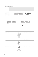
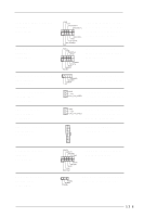
2.8 Connectors Connectors are NOT jumpers. DO NOT place jumper caps over these connectors. Connector Figure Description FDD connector (33-pin FLOPPY1) (see p.7 item 19) Pin1 FLOPPY1 Red marking Note: Match the red marking on the floppy ribbon cable with Pin1. Primary IDE connector (Blue) (39-pin IDE1, see p.7 item 10) Secondary IDE connector (Black) (39-pin IDE2, see p.7 item 9) PIN1 IDE1 PIN1 IDE2 connect the blue end connect the black end to the motherboard to the IDE devices 80-Pin ATA 100/133 cable Note: To optimize compatibility and performance, please connect your hard disk drive to the primary IDE connector (IDE1, blue) and CD-ROM to the secondary IDE connector (IDE2, black). USB 2.0 header (9-pin USB45) (see p.7 item 20) USB_PWR P-5 P+5 GND DUMMY 1 GND P+4 P-4 USB_PWR ASRock I/OTM provides 4 default USB 2.0 ports on the rear panel. If those 4 USB 2.0 ports on the rear panel are not sufficient, this USB 2.0 header is available for 2 additional USB 2.0 ports. Infrared module connector (5-pin IR1) (see p.7 item 21) Internal audio connectors (4-pin CD1, 4-pin AUX1) (CD1: see p.7 item 29) (AUX1: see p.7 item 30) IRTX +5V DUMMY 1 GND IRRX CD1 AUX1 This connector supports an optional wireless transmitting and receiving infrared module. These connectors allow you to receive stereo audio input from sound sources such as a CD-ROM, DVD-ROM, TV tuner card, or MPEG card. 16
-
 1
1 -
2
-
3
-
4
-
5
-
6
-
7
-
8
-
9
-
10
-
 11
11 -
 12
12 -
 13
13 -
 14
14 -
 15
15 -
 16
16 -
 17
17 -
 18
18 -
 19
19 -
 20
20 -
 21
21 -
22
-
23
-
24
-
25
-
26
-
27
-
28
-
29
-
30
 |
 |
