ASRock M3A785GM-LE User Manual
ASRock M3A785GM-LE Manual
 |
View all ASRock M3A785GM-LE manuals
Add to My Manuals
Save this manual to your list of manuals |
ASRock M3A785GM-LE manual content summary:
- ASRock M3A785GM-LE | User Manual - Page 1
M3A785GM-LE User Manual Version 1.0 Published November 2009 Copyright©2009 ASRock INC. All rights reserved. 1 - ASRock M3A785GM-LE | User Manual - Page 2
, without intent to infringe. Disclaimer: Specifications and information contained in this manual are furnished for informational use only and The Lithium battery adopted on this motherboard contains Perchlorate, a toxic substance controlled /perchlorate" ASRock Website: http://www.asrock.com 2 - ASRock M3A785GM-LE | User Manual - Page 3
1.1 Package Contents 5 1.2 Specifications 6 1.3 Minimum Hardware Requirement for 1080p Blu-ray (BD) / HD-DVD Playback Support 11 1.4 Motherboard Layout 12 1.5 I/O Panel 13 2 . Installation 14 Pre-installation Precautions 14 2.1 CPU Installation 15 2.2 Installation of CPU Fan and Heatsink 15 - ASRock M3A785GM-LE | User Manual - Page 4
BIOS Menu Bar 38 3.1.2 Navigation Keys 39 3.2 Main Screen 39 3.3 OC Tweaker Screen 40 3.4 Advanced Screen 47 3.4.1 CPU Screen 60 4 . Software Support 61 4.1 Install Operating System 61 4.2 Support CD Information 61 4.2.1 Running Support CD 61 4.2.2 Drivers Menu 61 4.2.3 Utilities Menu - ASRock M3A785GM-LE | User Manual - Page 5
our website for specific information about the model you are using. www.asrock.com/support/index.asp 1.1 Package Contents 1 x ASRock M3A785GM-LE Motherboard (Micro ATX Form Factor: 9.6-in x 7.8-in, 24.4 cm x 19.8 cm) 1 x ASRock M3A785GM-LE Quick Installation Guide 1 x ASRock M3A785GM-LE Support CD - ASRock M3A785GM-LE | User Manual - Page 6
FSB 2600 MHz (5.2 GT/s) - Supports Untied Overclocking Technology (see CAUTION 1) - Supports Hyper-Transport 3.0 (HT 3.0) Technology - Northbridge: AMD 785G - Southbridge: AMD SB710 - Dual Channel DDR3 Memory Technology (see CAUTION 2) - 2 x DDR3 DIMM slots - Support DDR3 1600(OC)/1333/1066/800 non - ASRock M3A785GM-LE | User Manual - Page 7
ACPI 1.1 Compliance Wake Up Events - Supports jumperfree - SMBIOS 2.3.1 Support - VCCM, NB Voltage Multi-adjustment - Supports Smart BIOS - Drivers, Utilities, AntiVirus Software (Trial Version), AMD OverDriveTM Utility, AMD Live! Explorer, AMD Fusion, ASRock Software Suite (CyberLink DVD Suite and - ASRock M3A785GM-LE | User Manual - Page 8
Whether 1600MHz memory speed is supported depends on the AM3 CPU you adopt. If you want to adopt DDR3 1600 memory module on this motherboard, please refer to the memory support list on our website for the compatible memory modules. ASRock website http://www.asrock.com 4. Due to the operating system - ASRock M3A785GM-LE | User Manual - Page 9
64-bit / VistaTM / XP 64-bit / XP SP1 or SP2. 9. It is a user-friendly ASRock overclocking tool which allows you to surveil ASRock website: http://www.asrock.com 11. ASRock Instant Flash is a BIOS flash utility embedded in Flash ROM. This convenient BIOS update tool allows you to update system BIOS - ASRock M3A785GM-LE | User Manual - Page 10
CPU fan on the motherboard functions properly and unplug the power cord, then plug it back again. To improve heat dissipation, remember to spray thermal grease between the CPU off mode condition. To meet EuP standard, an EuP ready motherboard and an EuP ready power supply are required. According to - ASRock M3A785GM-LE | User Manual - Page 11
only supported under Windows® 7 / 7 64-bit / VistaTM / VistaTM 64-bit OS. If you install Windows® XP / XP 64-bit OS, the function of 1080p Blu-ray (BD) / HD-DVD playback is not available, please visit our website for AMD 785G VGA driver update in the future. ASRock website http://www.asrock.com 11 - ASRock M3A785GM-LE | User Manual - Page 12
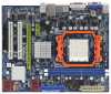
CD1 1 HD_AUDIO1 LPT1 1 PCIE1 AMD 785G Chipset Hybrid CrossFire PCIE2 M3A785GM-LE IDE1 PWR_FAN1 SATAII_4 SATAII_5 SATAII_6 (PORT 3) (PORT 4) (PORT 5) RoHS PCI1 IR1 1 FLOPPY1 PCI2 USB10_11 1 AMD SB710 Chipset SPEAKER1 1 PLED PWRBTN PANEL 1 1 HDLED RESET 8Mb BIOS USB8_9 1 CHA_FAN1 USB6_7 - ASRock M3A785GM-LE | User Manual - Page 13
1 2 3 4 5 6 7 11 10 9 8 1 PS/2 Mouse Port (Green) 2 VGA/D-Sub Port 3 VGA/DVI-D Port * 4 RJ-45 Port 5 Line In (Light Blue) 6 Front Speaker (Lime) to below steps for the software setting of Multi-Streaming. For Windows® XP: After restarting your computer, you will find "Mixer" tool on your - ASRock M3A785GM-LE | User Manual - Page 14
the power is switched off or the power cord is detached from the power supply. Failure to do so may cause severe damage to the motherboard, peripherals, and/or components. 1. Unplug the power cord from the wall socket before touching any component. 2. To avoid damaging the - ASRock M3A785GM-LE | User Manual - Page 15
. Make sure that the CPU and the heatsink are securely fastened and in good contact with each other. Then connect the CPU fan to the CPU FAN connector (CPU_FAN1, see Page 12, No. 6). For proper installation, please kindly refer to the instruction manuals of the CPU fan and the heatsink. 15 - ASRock M3A785GM-LE | User Manual - Page 16
Memory Modules (DIMM) M3A785GM-LE motherboard provides two 240-pin DDR3 (Double Data Rate 3) DIMM slots, and supports Dual Channel Memory Technology. before adding or removing DIMMs or the system components. Step 1. Step 2. Unlock a DIMM slot by pressing the retaining clips outward. Align a DIMM - ASRock M3A785GM-LE | User Manual - Page 17
2.4 Expansion Slots (PCI and PCI Express Slots) There are 2 PCI slots and 2 PCI Express slots on this motherboard. PCI slots: PCI slots are used to install expansion cards that have the 32-bit PCI interface. PCIE slots: PCIE1 (PCIE x1 slot; Green) is - ASRock M3A785GM-LE | User Manual - Page 18
after your system boots. If you haven't installed onboard VGA driver yet, please install onboard VGA driver from our support CD to your system and restart your computer. Then you can start to use dual monitor function on this motherboard. When you playback HDCP-protected video from Blu-ray (BD - ASRock M3A785GM-LE | User Manual - Page 19
when the add-on VGA card is inserted to this motherboard. 4. Install the onboard VGA driver and the add-on PCI Express VGA card driver to your system. If you have installed the drivers already, there is no need to install them again. 5. Set up a multi-monitor display. For Windows® XP / XP 64-bit OS - ASRock M3A785GM-LE | User Manual - Page 20
supported on this motherboard. To use HDCP function with this motherboard, you need to adopt the monitor that supports HDCP function as well. Therefore, you can enjoy the superior display quality with high-definition HDCP encryption contents. Please refer to below instruction HDCP specification is - ASRock M3A785GM-LE | User Manual - Page 21
2 . 6 ATITM Hybrid CrossFireXTM Operation Guide This motherboard supports ATITM Hybrid CrossFireXTM feature. ATITM Hybrid CrossFireXTM brings multi-GPU performance capabilities by enabling an AMD 785G integrated graphics processor and a discrete graphics processor to operate simultaneously with - ASRock M3A785GM-LE | User Manual - Page 22
system. Then you can freely enjoy the benefit of HybridTM CrossFireXTM feature. * Hybrid CrossFireXTM appearing here is a registered trademark of ATITM Technologies Inc., and is For further information of ATITM Hybrid CrossFireXTM technology, please check AMD website for up dates and details. 22 - ASRock M3A785GM-LE | User Manual - Page 23
and pin3 on CLRCMOS1 for 5 seconds. However, please do not clear the CMOS right after you update the BIOS. If you need to clear the CMOS when you just finish updating the BIOS, you must boot up the system first, and then shut it down before you do the clear-CMOS action - ASRock M3A785GM-LE | User Manual - Page 24
end to the motherboard connect the black end to the IDE devices 80-conductor ATA 66/100/133 cable Note: Please refer to the instruction of your IDE 0) (PORT 1) (PORT 2) These six Serial ATAII (SATAII) connectors support SATAII or SATA hard disk for internal storage devices. The current SATAII - ASRock M3A785GM-LE | User Manual - Page 25
SLCT SPD2 SPD1 SPD0 STB# Besides six default USB 2.0 ports on the I/O panel, there are three USB 2.0 headers on this motherboard. Each USB 2.0 header can support two USB 2.0 ports. This is an interface for print port cable that allows convenient connection of printer devices. Infrared Module - ASRock M3A785GM-LE | User Manual - Page 26
supports Jack Sensing, but the panel wire on the chassis must support HDA to function correctly. Please follow the instruction in our manual and chassis manual need to connect them for AC'97 audio panel. E. Enter BIOS Setup Utility. Enter Advanced Settings, and then select Chipset Configuration. - ASRock M3A785GM-LE | User Manual - Page 27
and match the black wire to the ground pin. Please connect the CPU fan cable to this connector and match the black wire to the ground pin. Though this motherboard provides 4-Pin CPU fan (Quiet Fan) support, the 3-Pin CPU fan still can work successfully even without the fan speed control function - ASRock M3A785GM-LE | User Manual - Page 28
guide. Some default setting of SATAII hard disks may not be at SATAII mode, which operate with the best performance. In order to enable SATAII function, please follow the below instruction 's website for details: http://www.hitachigst.com/hdd/support/download.htm The above examples are just for your - ASRock M3A785GM-LE | User Manual - Page 29
adopts AMD SB710 south bridge chipset that supports Serial ATA (SATA) / Serial ATAII (SATAII) hard disks and RAID (RAID 0, RAID 1, RAID 10 and JBOD) functions. You may install SATA / SATAII hard disks on this motherboard for internal storage devices. This section will guide you to install - ASRock M3A785GM-LE | User Manual - Page 30
Hot Plug and Hot Swap Functions for SATA / SATAII HDDs This motherboard supports Hot Plug and Hot Swap functions for SATA / SATAII Devices in RAID / AHCI mode. AMD SB710 south bridge chipset provides hardware support for Advanced Host controller Interface (AHCI), a new programming interface for SATA - ASRock M3A785GM-LE | User Manual - Page 31
is installed into system properly. The latest SATA / SATAII driver is available on our support website: www.asrock.com 4. Make sure to use the SATA power cable & data cable, which are from our motherboard package. 5. Please follow below instructions step by step to reduce the risk of HDD crash or - ASRock M3A785GM-LE | User Manual - Page 32
cable to (White) to the power supply 1x4-pin cable. the motherboard's SATAII connector. SATA power cable 1x4-pin power connector (White) Step attention, before you process the Hot Unplug: Please do follow below instruction sequence to process the Hot Unplug, improper procedure will cause the SATA - ASRock M3A785GM-LE | User Manual - Page 33
® XP / XP 64-bit With RAID Functions If you want to install Windows® XP or Windows® XP 64 BIOS. A. Enter BIOS SETUP UTILITY Advanced screen Storage Configuration. B. Set the "SATA Operation Mode" option to [RAID]. STEP 2: Make a SATA / SATAII Driver Diskette. A. Insert the ASRock Support - ASRock M3A785GM-LE | User Manual - Page 34
the instruction to install Windows® 7 / 7 64-bit / VistaTM / VistaTM 64-bit OS on your system. When you see "Where do you want to install Windows?" page, please insert the ASRock Support CD into your optical drive, and click the "Load Driver" button on the left on the bottom to load the AMD RAID - ASRock M3A785GM-LE | User Manual - Page 35
path in the Support CD: .. \ RAID Installation Guide NOTE2. Currently, if you install Windows® 7 / 7 64-bit / VistaTM / VistaTM 64-bit on IDE HDDs and there are no SATA / SATAII device used, please set up "SATA Operation Mode" to [IDE] in BIOS. 2.15 Installing Windows® XP / XP 64-bit / VistaTM - ASRock M3A785GM-LE | User Manual - Page 36
the instruction to install Windows® 7 / 7 64-bit / VistaTM / VistaTM 64-bit OS on your system. When you see "Where do you want to install Windows?" page, please insert the ASRock Support CD into your optical drive, and click the "Load Driver" button on the left on the bottom to load the AMD AHCI - ASRock M3A785GM-LE | User Manual - Page 37
This motherboard supports Untied Overclocking Technology, which means during overclocking, FSB enjoys better margin due to fixed PCI / PCIE buses. Before you enable Untied Overclocking function, please enter "Overclock Mode" option of BIOS setup to set the selection from [Auto] to [CPU, PCIE - ASRock M3A785GM-LE | User Manual - Page 38
the BIOS SETUP UTILITY to configure your system. The SPI Memory on the motherboard stores the BIOS SETUP UTILITY. You may run the BIOS SETUP UTILITY /date information OC Tweaker To set up overclocking features Advanced To set up the advanced BIOS features H/W Monitor To display current hardware - ASRock M3A785GM-LE | User Manual - Page 39
SETUP UTILITY Main OC Tweaker Advanced H/W Monitor System Overview System Time System Date [17:00:09] [Fri 11/27/2009] BIOS Version : M3A785GM-LE P1.0 Processor Type : AMD Phenom(tm) II X3 720 Processor (64bit) Processor Speed : 2800MHz Microcode Update : 100F42/1000086 L1 Cache Size : 384KB L2 - ASRock M3A785GM-LE | User Manual - Page 40
overclocking features. BIOS SETUP UTILITY Main OC Tweaker Advanced H/W Monitor Boot Security Exit EZ Overclocking Load Optimized CPU OC Setting [Press Enter] Load Optimized mGPU OC Setting [Press Enter] CPU Configuration Overclock Mode CPU Overclocking may cause damage to your CPU and motherboard - ASRock M3A785GM-LE | User Manual - Page 41
North Bridge Maximum Frequency Processor Maximum Voltage Multiplier/Voltage Change CPU Frequency Multiplier CPU Voltage x10.5 2100 MHZ x9.0 1800 MHz 1.2500 V [Manual] [x0.5 100 MHz] [0.6000 V] Overclocking may cause damage to your CPU and motherboard. It should be done at your own risk and expense - ASRock M3A785GM-LE | User Manual - Page 42
Bit] and [16 Bit]. CPU Thermal Throttle Use this item to enable CPU internal thermal control mechanism to keep the CPU from overheated. Configuration options: ] to [2.40V]. The default value is [Auto]. DRAM Timing BIOS SETUP UTILITY OC Tweaker DRAM Timing Memory Controller Mode Power Down Enable - ASRock M3A785GM-LE | User Manual - Page 43
Channel Interleaving This option appears only when you adopt Phenom CPU. It allows you to enable Channel Memory Interleaving. Configuration options: [Disabled], [XOR of Address bit [20:16, 6]], [XOR of Address bit [20:16, 9]], [Address bits 6] - ASRock M3A785GM-LE | User Manual - Page 44
TWRWR Use this to adjust TWRWR values. Configuration options: [Auto], [2CLK] to [10CLK]. The default value is [Auto]. TRDRD Use this to adjust TRWTTD values. Configuration options: [Auto], [3CLK] to [10CLK]. The default value is [Auto]. TRFC0 Use this to adjust TRFC0 values. Configuration options: [ - ASRock M3A785GM-LE | User Manual - Page 45
CHA CKE Drive Use this to adjust values for CHA CKE Drive. Configuration options: [Auto], [1.00x], [1.25x], [1.50x] and [2.00x]. The default value is [Auto]. CHA CS/ODT Drive Use this to adjust values for CHA CS/ODT Drive. Configuration options: [Auto], [1.00x], [1.25x], [1.50x] and [2.00x]. The - ASRock M3A785GM-LE | User Manual - Page 46
Chipset Settings Onboard GPU Clock Override This allows you to enable or disable the Onboard GPU Clock Override feature. Onboard GPU Clock This option only appears when you enable "Onboard GPU Clock Override". The default value is [500]. mGPU Voltage Use this to select mGPU voltage. Configuration - ASRock M3A785GM-LE | User Manual - Page 47
in below sections may cause system to malfunction. CPU Configuration Chipset Configuration ACPI Configuration Storage Configuration PCIPnP Configuration Floppy Configuration SuperIO Configuration USB Configuration BIOS Update Utility ASRock Instant Flash Select Screen Select Item Enter Go to - ASRock M3A785GM-LE | User Manual - Page 48
the additional hardware capabilities provided by AMD-V. The default value is [Enabled]. Configuration options: [Enabled] and [Disabled]. Enhance Halt State All processors support the Halt State (C1). The C1 state is supported through the native processor instructions HLT and MWAIT and requires no - ASRock M3A785GM-LE | User Manual - Page 49
BIOS you to select the type of Primary VGA in case of multiple video controllers. Configuration options: [Auto], [32MB], [64MB], [128MB], [256MB] and [512MB]. This option only AMD 785G. Surround View This allows you to enable or disable the Surround View feature or Hybrid CrossFireXTM feature. 49 - ASRock M3A785GM-LE | User Manual - Page 50
3.4.3 ACPI Configuration BIOS SETUP UTILITY Advanced ACPI Settings Suspend To RAM Away Mode Support Restore on AC / Power or disable the feature Check Ready Bit. Away Mode Support Use this item to enable or disable Away Mode support under Windows® XP Media Center OS. The default value is [Disabled - ASRock M3A785GM-LE | User Manual - Page 51
plan to use this motherboard to submit Windows® VistaTM certification. 3.4.4 Storage Configuration BIOS SETUP UTILITY Advanced Storage as the example in the following instruction, which can be applied to the configurations of "IDE1 Slave" as well. BIOS SETUP UTILITY Advanced IDE Master Device - ASRock M3A785GM-LE | User Manual - Page 52
Installed] to disable the use of IDE device. [Auto]: Select [Auto] to automatically detect the hard disk drive. After selecting the hard disk information into BIOS, use a disk utility, such as FDISK, to partition and format the new IDE hard disk drives. This is necessary so that you can write or - ASRock M3A785GM-LE | User Manual - Page 53
3.4.5 PCIPnP Configuration BIOS SETUP UTILITY Advanced Advanced PCI / PnP Settings PCI Latency Timer is recommended to keep the default value unless the installed PCI expansion cards' specifications require other settings. PCI IDE BusMaster Use this item to enable or disable the PCI IDE - ASRock M3A785GM-LE | User Manual - Page 54
Address Parallel Port Mode EPP Version ECP Mode DMA Channel Parallel Port IRQ [Enabled] [3F8 / IRQ4] [Disabled] [378] [ECP + EPP] [1.9] [DMA3] [IRQ7] Allow BIOS to Enable or Disable Floppy Controller. +F1 F9 F10 ESC Select Screen Select Item Change Option General Help Load Defaults Save and Exit - ASRock M3A785GM-LE | User Manual - Page 55
Parallel Port Address Use this item to set the address for the onboard parallel port or disable it. Configuration options: [Disabled], [378], and [278]. Parallel Port Mode Use this item to set the operation mode of the parallel port. The default value is [ECP+EPP]. If this option is set to [ECP+EPP - ASRock M3A785GM-LE | User Manual - Page 56
Use this item to enable or disable the USB 2.0 support. Legacy USB Support Use this option to select legacy support for USB devices. There are four configuration options: [Enabled], [Auto], [Disabled] and [BIOS Setup Only]. The default value is [Enabled]. Please refer to below descriptions for - ASRock M3A785GM-LE | User Manual - Page 57
to monitor the status of the hardware on your system, including the parameters of the CPU temperature, motherboard temperature, CPU fan speed, chassis fan speed, and the critical voltage. BIOS SETUP UTILITY Main OC Tweaker Advanced H/W Monitor Boot Security Exit Hardware Health Event Monitoring - ASRock M3A785GM-LE | User Manual - Page 58
F1 General Help F9 Load Defaults F10 Save and Exit ESC Exit v02.54 (C) Copyright 1985-2005, American Megatrends, Inc. 3.6.1 Boot Settings Configuration BIOS SETUP UTILITY Boot Boot Settings Configuration Full Screen Logo AddOn ROM Display Boot Logo Boot From Onboard LAN Bootup Num-Lock [Enabled - ASRock M3A785GM-LE | User Manual - Page 59
the option "Full Screen Logo". Configuration options: [Auto], [EuP], [Scenery] and [ASRock]. The default value is [Auto]. Currently, the option [Auto] is set to system. For the user password, you may also clear it. BIOS SETUP UTILITY Main OC Tweaker Advanced H/W Monitor Boot Security Exit Security - ASRock M3A785GM-LE | User Manual - Page 60
. Discard Changes When you select this option, it will pop-out the following message, "Discard changes?" Select [OK] to discard all changes. Load BIOS Defaults Load BIOS default values for all the setup questions. F9 key can be used for this operation. Load Performance Setup Default (IDE/SATA) This - ASRock M3A785GM-LE | User Manual - Page 61
install the necessary drivers to activate the devices. 4.2.3 Utilities Menu The Utilities Menu shows the applications software that the motherboard supports. Click on a specific item then follow the installation wizard to install it. 4.2.4 Contact Information If you need to contact ASRock or want to
-
 1
1 -
 2
2 -
 3
3 -
 4
4 -
 5
5 -
 6
6 -
 7
7 -
8
-
9
-
10
-
11
-
12
-
13
-
14
-
15
-
16
-
17
-
18
-
19
-
20
-
21
-
22
-
23
-
24
-
25
-
26
-
27
-
28
-
29
-
30
-
31
-
32
-
33
-
34
-
35
-
36
-
37
-
38
-
39
-
40
-
41
-
42
-
43
-
44
-
45
-
46
-
47
-
48
-
49
-
50
-
51
-
52
-
53
-
54
-
55
-
56
-
57
-
58
-
59
-
60
-
61
 |
 |
1
M3A785GM-LE
User Manual
Version 1.0
Published November 2009
Copyright©2009 ASRock INC. All rights reserved.