ASRock M3A790GXH/USB3 User Manual
ASRock M3A790GXH/USB3 Manual
 |
View all ASRock M3A790GXH/USB3 manuals
Add to My Manuals
Save this manual to your list of manuals |
ASRock M3A790GXH/USB3 manual content summary:
- ASRock M3A790GXH/USB3 | User Manual - Page 1
M3A790GXH/USB3 User Manual Version 1.0 Published January 2010 Copyright©2010 ASRock INC. All rights reserved. 1 - ASRock M3A790GXH/USB3 | User Manual - Page 2
any form or by any means, except duplication of documentation by the purchaser for backup purpose, without written consent of ASRock Inc. Products and corporate names appearing in this manual may or may not be registered trademarks or copyrights of their respective companies, and are used only for - ASRock M3A790GXH/USB3 | User Manual - Page 3
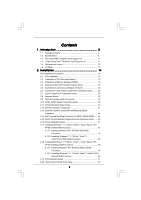
16 2.4 Expansion Slots (PCI and PCI Express Slots 18 2.5 Dual Monitor and Surround Display Features 20 2.6 CrossFireXTM and 3-Way CrossFireXTM Operation Guide ........ 23 2.7 Hybrid CrossFireXTM Operation Guide 30 2.8 Jumpers Setup 32 2.9 Onboard Headers and Connectors 33 2.10 HDMI_SPDIF Header - ASRock M3A790GXH/USB3 | User Manual - Page 4
UTILITY 54 3.1 Introduction 54 3.1.1 BIOS Menu Bar 54 3.1.2 Navigation Keys 72 3.4.8 Super IO Configuration 72 3.4.9 USB Configuration 73 3.5 Hardware Health Event 77 4 . Software Support 78 4.1 Install Operating System 78 4.2 Support CD Information 78 4.2.1 Running Support CD 78 4.2.2 - ASRock M3A790GXH/USB3 | User Manual - Page 5
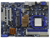
Package Contents ASRock M3A790GXH/USB3 Motherboard (ATX Form Factor: 12.0-in x 8.8-in, 30.5 cm x 22.4 cm) ASRock M3A790GXH/USB3 Quick Installation Guide ASRock M3A790GXH/USB3 Support CD 1 x Ultra ATA 66/100/133 IDE Ribbon Cable (80-conductor) 1 x Ribbon Cable for a 3.5-in Floppy Drive 4 x Serial ATA - ASRock M3A790GXH/USB3 | User Manual - Page 6
- Northbridge: AMD 790GX - Southbridge: AMD SB750 - Dual Channel DDR3 Memory Technology (see CAUTION 2) - 4 x DDR3 DIMM slots - Support DDR3 1600(OC)/1333/1066/800 non-ECC, un-buffered memory (see CAUTION 3) - Max. capacity of system memory: 16GB (see CAUTION 4) - 3 x PCI Express 2.0 x16 slots - ASRock M3A790GXH/USB3 | User Manual - Page 7
IEEE 1394 header - 1 x HDMI_SPDIF header - CPU/Chassis/NB/Power FAN connector - 24 pin ATX power connector - 8 pin 12V power connector - SLI/XFIRE power connector - CD in header - Front panel audio connector - 3 x USB 2.0 headers (support 6 USB 2.0 ports) (see CAUTION 11) - 8Mb AMI BIOS - AMI Legal - ASRock M3A790GXH/USB3 | User Manual - Page 8
-adjustment - Supports Smart BIOS Support CD - Drivers, Utilities, AntiVirus Software (Trial Version), AMD OverDriveTM Utility, AMD Live! Explorer, AMD Fusion, ASRock Software Suite (CyberLink DVD Suite - OEM and Trial; Creative Sound Blaster X-Fi MB - Trial) Unique Feature - ASRock OC Tuner - ASRock M3A790GXH/USB3 | User Manual - Page 9
installing SATAII hard disk to SATAII connector, please read the "SATAII Hard Disk Setup Guide" on page 42 to adjust your SATAII hard disk drive to SATAII mode. You can also connect SATA hard disk to SATAII connector directly. 10. This motherboard supports eSATAII interface, the external SATAII - ASRock M3A790GXH/USB3 | User Manual - Page 10
key during the POST or press key to BIOS setup menu to access ASRock Instant Flash. Just launch this tool and save the new BIOS file to your USB flash drive, floppy disk or hard drive, then you can update your BIOS only in a few clicks without preparing an additional floppy diskette or - ASRock M3A790GXH/USB3 | User Manual - Page 11
/ VistaTM 64-bit only. * For the latest updates of the supported PCI Express VGA card list for CrossFireXTM Mode, please visit our website for details. ASRock website: http://www.asrock.com/support/index.htm 1.4 Three CrossFireXTM Graphics Card Support List (for Windows® VistaTM / VistaTM 64-bit - ASRock M3A790GXH/USB3 | User Manual - Page 12
Bottom: 790GX NB_FAN1 41 PWR_FAN1 Chipset PCIE1 LAN PHY 40 M3A790GXH/USB3 39 PCIE2 IDE1 CrossFireX Hybrid CrossFire 38 37 36 35 34 Super I/O AUDIO CODEC HDMI_SPDIF1 1 CD1 HD_AUDIO1 1 PCIE3 PCI1 PCI Express 2.0 PCIE4 EuP Ready COM1 1 PCI2 FLOPPY1 CMOS BATTERY AMD SB750 Chipset - ASRock M3A790GXH/USB3 | User Manual - Page 13
USB 2.0 Ports (USB45) * There are two LED next to the LAN port. Please refer to the table below for the LAN port LED indications. LAN Port LED Indications Activity/Link LED SPEED LED Status Description Status Description ACT/LINK SPEED V V V V *** To support AC3 or DTS audio format with - ASRock M3A790GXH/USB3 | User Manual - Page 14
2. Installation This is an ATX form factor (12.0-in x 8.8-in, 30.5 cm x 22.4 cm) motherboard. Before you install the motherboard, study the configuration of your chassis to ensure that the - ASRock M3A790GXH/USB3 | User Manual - Page 15
that the CPU and the heatsink are securely fastened and in good contact with each other. Then connect the CPU fan to the CPU FAN connector (CPU_FAN1, see Page 12, No. 3). For proper installation, please kindly refer to the instruction manuals of the CPU fan and the heatsink. 15 - ASRock M3A790GXH/USB3 | User Manual - Page 16
Modules (DIMM) This motherboard provides four 240-pin DDR3 (Double Data Rate 3) DIMM slots, and supports Dual Channel Memory Technology. For dual channel configuration, you always need to install identical (the same brand, speed, size and chip-type) DDR3 DIMM pair in the slots of the same color. In - ASRock M3A790GXH/USB3 | User Manual - Page 17
Installing a DIMM Please make sure to disconnect power supply before adding or removing DIMMs or the system components. Step 1. Step 2. Unlock a DIMM slot by pressing the retaining clips outward. Align a DIMM on the slot such that the notch on the DIMM matches the break on the slot. notch break - ASRock M3A790GXH/USB3 | User Manual - Page 18
used to install PCI Express graphics cards to support 3-Way CrossFireXTM function. 1. If you plan to install only one PCI Express VGA card on this motherboard, please install it on PCIE2 slot. In this mode, you do not need to adjust the default setting of ASRock SLI/XFire Switch Card, and please do - ASRock M3A790GXH/USB3 | User Manual - Page 19
Step 3. Remove the bracket facing the slot that you intend to use. Keep the screws for later use. Step 4. Align the card connector with the slot and press firmly until the card is completely seated on the slot. Step 5. Fasten the card to the chassis with screws. Step 6. Replace the system cover. 19 - ASRock M3A790GXH/USB3 | User Manual - Page 20
of dual monitor feature without installing any add-on VGA card to this motherboard. This motherboard also provides independent display controllers for DVI-D, D-Sub and HDMI to support dual VGA output so that DVI-D, D-sub and HDMI can drive same or different display contents. To enable dual monitor - ASRock M3A790GXH/USB3 | User Manual - Page 21
to HDMI port on the I/O panel. Then connect other monitor cables to the corresponding connectors of the add-on PCI Express VGA cards on PCIE2, PCIE3 and PCIE4 slots. 4. Boot your system. Press to enter BIOS setup. Enter "Share Memory" option to adjust the memory capability to [32MB], [64MB - ASRock M3A790GXH/USB3 | User Manual - Page 22
function with this motherboard, you need to adopt the monitor that supports HDCP function as well. Therefore, you can enjoy the superior display quality with high-definition HDCP encryption contents. Please refer to below instruction for more details about HDCP function. What is HDCP? HDCP stands - ASRock M3A790GXH/USB3 | User Manual - Page 23
has released or will release in the future, please refer to ATITM graphics card manuals for detailed installation guide. Step 1. There is one ASRock SLI/XFire Switch Card factory-mounted on this motherboard. This card served as a switch between the default mode (x16) and CrossFireXTM mode (x8 / x8 - ASRock M3A790GXH/USB3 | User Manual - Page 24
the direction of ASRock SLI/XFire Switch Card. Please simultaneously pull open both the retention arms that hold the card in position. The card itself will spring the card into position. Also, keep away from touching the connectors (Golden Fingers). Step 5. Install one Radeon graphics card to PCIE2 - ASRock M3A790GXH/USB3 | User Manual - Page 25
DVI monitor cable to the DVI connector on the Radeon graphics card on PCIE2 slot. (You may use the DVI to D-Sub adapter to convert the DVI connector to D-Sub interface, and then connect the D-Sub monitor cable to the DVI to D-Sub adapter.) Step 9. Connect a 4-pin ATX power cable to SLI/XFIRE power - ASRock M3A790GXH/USB3 | User Manual - Page 26
page 23 and 24 to reverse the direction of ASRock SLI/XFire Switch Card. Install one Radeon graphics card to PCIE2 slot. For the proper installation procedures, please refer to section "Expansion Slots". Step 3. Install one Radeon graphics card to PCIE3 slot. For the proper installation procedures - ASRock M3A790GXH/USB3 | User Manual - Page 27
DVI monitor cable to the DVI connector on the Radeon graphics card on PCIE2 slot. (You may use the DVI to D-Sub adapter to convert the DVI connector to D-Sub interface, and then connect the D-Sub monitor cable to the DVI to D-Sub adapter.) Step 7. Connect a 4-pin ATX power cable to SLI/XFIRE power - ASRock M3A790GXH/USB3 | User Manual - Page 28
driver updates. Step 3. Step 4. Step 5. Install the required drivers to your system. For Windows® XP OS: A. ATITM recommends Windows® XP Service Please check AMD website for details. Restart your computer. Install the VGA card drivers to your system, and restart your computer. Then you will find - ASRock M3A790GXH/USB3 | User Manual - Page 29
for identification or explanation and to the owners' benefit, without intent to infringe. * For further information of ATITM CrossFireXTM technology, please check AMD website for updates and details. 29 - ASRock M3A790GXH/USB3 | User Manual - Page 30
and a motherboard based on an AMD 790GX integrated chipset, all operating in a Windows® VistaTM environment. Please refer to below PCI Express graphics card support list for ATITM Hybrid CrossFireXTM. For the future update of more compatible PCI Express graphics cards, please visit our website for - ASRock M3A790GXH/USB3 | User Manual - Page 31
Step 8. Double-click "ATI Catalyst Control Center". Click "View", click "CrossFireTM", and then select the option "Enable CrossFireTM". View CrossFireTM Enable CrossFireTM Step 9. Click "Yes" to continue. Step 10. Click "OK" to save your change. Step 11. Reboot your system. Then you can freely - ASRock M3A790GXH/USB3 | User Manual - Page 32
enable (see p.12, No. 2) +5V +5VSB +5VSB (standby) for PS/2 or USB wake up events. Note: To select +5VSB, it requires 2 Amp and higher standby not clear the CMOS right after you update the BIOS. If you need to clear the CMOS when you just finish updating the BIOS, you must boot up the system - ASRock M3A790GXH/USB3 | User Manual - Page 33
/100/133 cable Note: Please refer to the instruction of your IDE device vendor for the details. Serial ATAII Connectors (SATAII_1: see p.12, No. 17) ( p.12, No. 23) SATAII_6 These six Serial ATAII (SATAII) connectors support SATAII or SATA hard disk for internal SATAII_1 SATAII_2 storage devices. - ASRock M3A790GXH/USB3 | User Manual - Page 34
to the power connector on each drive. Then connect the white end of SATA power cable to the power connector of the power supply. Besides six default USB 2.0 ports on the I/O panel, there are three USB 2.0 headers on this motherboard. Each USB 2.0 header can support two USB 2.0 ports. This header - ASRock M3A790GXH/USB3 | User Manual - Page 35
supports Jack Sensing, but the panel wire on the chassis must support HDA to function correctly. Please follow the instruction in our manual and chassis manual audio panel. E. Enter BIOS Setup Utility. Enter bit OS: Click "Audio I/O", select "Connector Settings" , choose "Disable front panel - ASRock M3A790GXH/USB3 | User Manual - Page 36
2 GND 1 Please connect the CPU fan cable to this connector and match the black wire to the ground pin. Though this motherboard provides 4-Pin CPU fan (Quiet Fan) support, the 3-Pin CPU fan still can work successfully even without the fan speed control function. If you plan to connect the 3-Pin - ASRock M3A790GXH/USB3 | User Manual - Page 37
1394 header can support one IEEE 1394 port. This COM1 header supports a serial port module. HDMI_SPDIF header, providing SPDIF audio output to HDMI VGA card, allows the system to connect HDMI Digital TV/ projector/LCD devices. Please connect the HDMI_SPDIF connector of HDMI VGA card to this header - ASRock M3A790GXH/USB3 | User Manual - Page 38
of HDMI_SPDIF cable to the HDMI_SPDIF header on the motherboard. Then connect the white end (B or C) of HDMI_SPDIF cable to the HDMI_SPDIF connector of HDMI VGA card. A. black end +5V SPDIFOUT GND blue black B. white end (2-pin) SPDIFOUT GND blue black C. white end (3-pin) SPDIFOUT GND blue - ASRock M3A790GXH/USB3 | User Manual - Page 39
shows the wrong example of connecting HDMI_SPDIF cable to the fan connector of PCI Express VGA card. Please refer to the VGA card user manual for connector usage in advance. Step 4. Step 5. Connect the HDMI output connector on HDMI VGA card to HDMI device, such as HDTV. Please refer to the user - ASRock M3A790GXH/USB3 | User Manual - Page 40
guide. Some default setting of SATAII hard disks may not be at SATAII mode, which operate with the best performance. In order to enable SATAII function, please follow the below instruction 's website for details: http://www.hitachigst.com/hdd/support/download.htm The above examples are just for your - ASRock M3A790GXH/USB3 | User Manual - Page 41
advantageous transfer speed and the facilitating mobile capability, in the near future, eSATAII will replace USB 2.0 and IEEE 1394 to be a trend for external interface. NOTE: 1. If you set "SATA Operation Mode" option in BIOS setup to AHCI or RAID mode, Hot Plug function is supported with eSATAII - ASRock M3A790GXH/USB3 | User Manual - Page 42
(eSATAII_TOP; see p.12 No.42) with a SATA data cable first. Connect the SATA data Cable to the SATAII connector (SATAII_6) Connect the SATA data cable to the eSATAII connector (eSATAII_TOP) 2. Use the eSATAII device cable to connect eSATAII device and the eSATAII port of the I/O shield. Connect - ASRock M3A790GXH/USB3 | User Manual - Page 43
Comparison between eSATAII and other devices IEEE 1394 USB 2.0 SATA eSATAII/SATAII 400Mb/s 480Mb/s 1.5Gb/s (1500Mb/s) 3.0Gb/s (3000Mb/s) 43 - ASRock M3A790GXH/USB3 | User Manual - Page 44
devices. This section will guide you to install the SATA / SATAII hard disks. STEP 1: Install the SATA / SATAII hard disks into the drive bays of your chassis. SATAII Devices in RAID / AHCI mode. AMD SB750 south bridge chipset provides hardware support for Advanced Host controller Interface (AHCI), a - ASRock M3A790GXH/USB3 | User Manual - Page 45
into system properly. The latest SATA / SATAII driver is available on our support website: www.asrock.com 4. Make sure to use the SATA power cable & data cable, which are from our motherboard package. 5. Please follow below instructions step by step to reduce the risk of HDD crash or data loss - ASRock M3A790GXH/USB3 | User Manual - Page 46
Connect SATA 15-pin power cable connector (Black) end to SATA / SATAII HDD. Step 4 Connect SATA data cable to the SATA / SATAII HDD. How to Hot Unplug a SATA / SATAII HDD: Points of attention, before you process the Hot Unplug: Please do follow below instruction sequence to process the Hot Unplug - ASRock M3A790GXH/USB3 | User Manual - Page 47
below steps. STEP 1: Set up BIOS. A. Enter BIOS SETUP UTILITY Advanced screen Storage Configuration. B. Set the "SATA Operation Mode" option to [RAID]. STEP 2: Make a SATA / SATAII Driver Diskette. A. Insert the ASRock Support CD into your optical drive to boot your system. B. During - ASRock M3A790GXH/USB3 | User Manual - Page 48
to boot your system, and follow the instruction to install Windows® 7 / 7 64-bit / VistaTM / VistaTM 64-bit OS on your system. When you see "Where do you want to install Windows?" page, please insert the ASRock Support CD into your optical drive, and click the "Load Driver" button on the left - ASRock M3A790GXH/USB3 | User Manual - Page 49
still need to set up "SATA Operation Mode" to [RAID] in BIOS first. Then, please set the RAID configuration by using the Windows RAID installation guide in the following path in the Support CD: .. \ RAID Installation Guide NOTE2. Currently, if you install Windows® 7 / 7 64-bit / VistaTM / VistaTM 64 - ASRock M3A790GXH/USB3 | User Manual - Page 50
functions STEP 1: Set Up BIOS. A. Enter BIOS SETUP UTILITY Advanced screen Storage instruction to install Windows® 7 / 7 64-bit / VistaTM / VistaTM 64-bit OS on your system. When you see "Where do you want to install Windows?" page, please insert the ASRock Support CD into your optical drive - ASRock M3A790GXH/USB3 | User Manual - Page 51
2.19 DTS Operation Guide DTS (Digital Theater Systems) is a multi-channel digital surround sound content. Please follow below steps to enable DTS function: 1. Install the drivers to your system from ASRock support CD. 2. Reboot your system. 3. You will find the icon (Realtek HD Audio Manager) - ASRock M3A790GXH/USB3 | User Manual - Page 52
Music Mode Cinema Mode Music Mode The music mode is for use with any stereo music recordings, which preserves the integrity of the stereo mix while augmenting it with a center channel to anchor the image, and deriving enough surround content to yield a spacious, three-dimensional listening - ASRock M3A790GXH/USB3 | User Manual - Page 53
20 Untied Overclocking Technology This motherboard supports Untied Overclocking Technology, which means during overclocking, FSB enjoys better margin due to fixed PCI / PCIE buses. Before you enable Untied Overclocking function, please enter "Overclock Mode" option of BIOS setup to set the selection - ASRock M3A790GXH/USB3 | User Manual - Page 54
Power-On-Self-Test (POST) to enter the BIOS SETUP UTILITY, otherwise, POST will continue with its test routines. If you wish to enter the BIOS SETUP UTILITY after and then back on. Because the BIOS software is constantly being updated, the following BIOS setup screens and descriptions are for - ASRock M3A790GXH/USB3 | User Manual - Page 55
Security Exit System Overview System Time System Date [17:00:09] [Fri 01/29/2010] BIOS Version : M3A790GXH/USB3 P1.0 Processor Type : AMD Engineering Sample (64bit) Processor Speed : 2500MHz Microcode Update : 100F41/1000086 L1 Cache Size : 512KB L2 Cache Size : 2048KB L3 Cache Size : 6144KB - ASRock M3A790GXH/USB3 | User Manual - Page 56
Load Performance Setup Default (IDE/SATA) Load Performance Setup AHCI Mode Load Performance Setup RAID Mode Load Power Saving Setup Default BIOS Update Utility ASRock Instant Flash Exit system setup after saving the changes. F10 key can be used for this operation. Select Screen Select Item Enter Go - ASRock M3A790GXH/USB3 | User Manual - Page 57
ASRock Instant Flash ASRock Instant Flash is a BIOS flash utility embedded in Flash ROM. This convenient BIOS update tool allows you to update system BIOS without entering operating systems first like MS-DOS or Windows®. Just launch this tool and save the new BIOS file to your USB flash drive, - ASRock M3A790GXH/USB3 | User Manual - Page 58
Configuration, Floppy Configuration, SuperIO Configuration, and USB Configuration. BIOS SETUP UTILITY Main Smart Advanced H/W Monitor If AUTO, multiplier and voltage will be left at the rated frequency/voltage. If Manual, multiplier and voltage will be set based on User Selection in Setup. +F1 F9 - ASRock M3A790GXH/USB3 | User Manual - Page 59
processors support the Halt State (C1). The C1 state is supported through the native processor instructions HLT and MWAIT and requires no hardware support from item is set to [Auto] by default. If it is set to [Manual], you may adjust the value of Processor Frequency and Processor Voltage. However, - ASRock M3A790GXH/USB3 | User Manual - Page 60
BIOS multiplier and voltage will be left at the rated frequency/voltage. If Manual, multiplier and voltage will be set based on User Selection in Setup. adjust the value of this item. HT Bus Speed This feature allows you selecting Hyper-Transport bus speed. Configuration options: [Auto],[x1 200 MHz] - ASRock M3A790GXH/USB3 | User Manual - Page 61
3.4.2 Memory Configuration BIOS SETUP UTILITY Advanced Memory Configuration Memory Clock Memory Controller Mode Power Down Enable Bank Interleaving Channel Interleaving Timing : 4-4-4-12 CAS Latency (CL) TRCD TRP TRAS - ASRock M3A790GXH/USB3 | User Manual - Page 62
TRAS Use this to adjust TRAS values. Configuration options: [Auto], [15CLK] to [30CLK]. The default value is [Auto]. TRTP Use this to adjust TRTP values. Configuration options: [Auto], [4CLK] to [7CLK]. The default value is [Auto]. TRRD Use this to adjust TRRD values. Configuration options: [Auto], - ASRock M3A790GXH/USB3 | User Manual - Page 63
CHB CS/ODT Setup Time feature. Configuration options: [Auto], [1/2CLK] and [1CLK]. The default value is [Auto]. CHA CKE Drive Strength Use this to adjust values for CHA CKE Drive Strength. Configuration options: [Auto], [1.00x], [1.25x], [1.50x] and [2.00x]. The default value is [Auto]. CHA CS/ODT - ASRock M3A790GXH/USB3 | User Manual - Page 64
Processor ODT. Configuration options: [Auto], [240 ohms], [120 ohms] and [60 ohms]. The default value is [Auto]. CHB CKE Drive Strength Use this to adjust values for CHB CKE Drive Strength. Configuration options: [Auto], [1.00x], [1.25x], [1.50x] and [2.00x]. The default value is [Auto]. CHB CS/ODT - ASRock M3A790GXH/USB3 | User Manual - Page 65
BIOS SETUP UTILITY Advanced Chipset Settings Onboard HD Audio Front Panel OnBoard Lan Onboard IEEE 1394 Primary Graphics Adapter [Auto] [Auto] [Enabled] [Enabled] [PCI] Internal Graphics Mode Share Memory SidePort Clock Speed Audio will be disabled when PCI Sound Card is plugged. Front Panel - ASRock M3A790GXH/USB3 | User Manual - Page 66
This allows you to select sideport clock speed. The default value is [Auto]. Configuration options: [Auto], [400 MHz], [ HD Audio This allows you to enable or disable the onboard HDMI HD Audio in AMD 790GX. Onboard GPU Clock Override This allows you to enable or disable the Onboard GPU Clock - ASRock M3A790GXH/USB3 | User Manual - Page 67
50%], [62.5%], [75%] and [87.5%]. The default value is [Auto]. 3.4.4 ACPI Configuration BIOS SETUP UTILITY Advanced ACPI Settings Suspend To RAM Check Ready Bit Away Mode Support Restore on AC / Power Loss Ring-In Power On PCI Devices Power On PS / 2 Keyboard Power On RTC Alarm Power On ACPI HPET - ASRock M3A790GXH/USB3 | User Manual - Page 68
On Use this item to enable or disable PCI devices to turn on the system from the power-soft-off mode. PS/2 Keyboard Power On Use this item to enable or disable PS/2 keyboard - ASRock M3A790GXH/USB3 | User Manual - Page 69
configuration for the device that you specify. We will use the "IDE1 Master" as the example in the following instruction, which can be applied to the configurations of "IDE1 Slave" as well. BIOS SETUP UTILITY Advanced IDE Master Device Vendor Size LBA Mode Block Mode PIO Mode Async DMA Ultra DMA - ASRock M3A790GXH/USB3 | User Manual - Page 70
hard disk drive. After selecting the hard disk information into BIOS, use a disk utility, such as FDISK, to partition and format the new IDE hard disk drives. This is timing. DMA Mode DMA capability allows the improved transfer-speed and data-integrity for compatible IDE devices. S.M.A.R.T. Use - ASRock M3A790GXH/USB3 | User Manual - Page 71
Setting wrong values in this section may cause the system to malfunction. PCI Latency Timer The default value is 32. It is recommended to keep the default value unless the installed PCI expansion cards' specifications require other settings. PCI IDE BusMaster Use this item to enable or disable the - ASRock M3A790GXH/USB3 | User Manual - Page 72
3.4.7 Floppy Configuration In this section, you may configure the type of your floppy drive. BIOS SETUP UTILITY Advanced Floppy Configuration Floppy A [1.44 MB 312"] Select the type of floppy drive connected to the system. +F1 F9 F10 ESC Select Screen Select Item Change Option General Help - ASRock M3A790GXH/USB3 | User Manual - Page 73
or disable the use of USB controller. USB 2.0 Support Use this item to enable or disable the USB 2.0 support. Legacy USB Support Use this option to select legacy support for USB devices. There are four configuration options: [Enabled], [Auto], [Disabled] and [BIOS Setup Only]. The default value - ASRock M3A790GXH/USB3 | User Manual - Page 74
hardware on your system, including the parameters of the CPU temperature, motherboard temperature, CPU fan speed, chassis fan speed, and the critical voltage. BIOS SETUP UTILITY Main Smart Advanced H/W Monitor Boot Security Exit Hardware Health Event Monitoring CPU Temperature M / B Temperature - ASRock M3A790GXH/USB3 | User Manual - Page 75
Drives [1st Floppy Device] [HDD: PM - HDS722580VL] [CD / DVD: 3S - CD - ROM C] [USB] [USB] Select Screen Select Item Enter Go to Sub Screen F1 General Help F9 Load Defaults F10 Save and Exit ESC Exit v02.54 (C) Copyright 1985-2005, American Megatrends, Inc. 3.6.1 Boot Settings Configuration BIOS - ASRock M3A790GXH/USB3 | User Manual - Page 76
"Full Screen Logo". Configuration options: [Auto], [PCIE2.0 Revolution], [Scenery] and [ASRock]. The default value is [Auto]. Currently, the option [Auto] is set to system. For the user password, you may also clear it. BIOS SETUP UTILITY Main Smart Advanced H/W Monitor Boot Security Exit Security - ASRock M3A790GXH/USB3 | User Manual - Page 77
and exit setup?" Select [OK] to save the changes and exit the BIOS SETUP UTILITY. Discard Changes and Exit When you select this option, it message, "Discard changes and exit setup?" Select [OK] to exit the BIOS SETUP UTILITY without saving any changes. Discard Changes When you select this option - ASRock M3A790GXH/USB3 | User Manual - Page 78
with the motherboard contains necessary drivers and useful utilities that enhance the motherboard features. 4.2.1 Running The Support CD To begin using the support CD, insert the CD into your CD-ROM drive. The CD automatically displays the Main Menu if "AUTORUN" is enabled in your computer. If the
-
 1
1 -
 2
2 -
 3
3 -
 4
4 -
 5
5 -
 6
6 -
 7
7 -
8
-
9
-
10
-
11
-
12
-
13
-
14
-
15
-
16
-
17
-
18
-
19
-
20
-
21
-
22
-
23
-
24
-
25
-
26
-
27
-
28
-
29
-
30
-
31
-
32
-
33
-
34
-
35
-
36
-
37
-
38
-
39
-
40
-
41
-
42
-
43
-
44
-
45
-
46
-
47
-
48
-
49
-
50
-
51
-
52
-
53
-
54
-
55
-
56
-
57
-
58
-
59
-
60
-
61
-
62
-
63
-
64
-
65
-
66
-
67
-
68
-
69
-
70
-
71
-
72
-
73
-
74
-
75
-
76
-
77
-
78
 |
 |
1
M3A790GXH/USB3
User Manual
Version 1.0
Published January 2010
Copyright©2010 ASRock INC. All rights reserved.