ASRock P4VT8 User Manual
ASRock P4VT8 Manual
 |
View all ASRock P4VT8 manuals
Add to My Manuals
Save this manual to your list of manuals |
ASRock P4VT8 manual content summary:
- ASRock P4VT8 | User Manual - Page 1
P4VT8+ User Manual Version 1.0 Published January 2004 Copyright©2004 ASRock INC. All rights reserved. 1 - ASRock P4VT8 | User Manual - Page 2
backup purpose, without written consent of ASRock Inc. Products and corporate names appearing in this manual may or may not be registered trademarks benefit, without intent to infringe. Disclaimer: Specifications and information contained in this manual are furnished for informational use only and - ASRock P4VT8 | User Manual - Page 3
14 2.9 Serial ATA (SATA) Hard Disks Installation 17 2.9.1 Installation of Windows 2000 / Windows XP ........ 18 2.9.2 RAID 0 / RAID 1 Configurations 18 2.9.2.1 Guide to Configure RAID 0 19 2.9.2.2 Guide to Configure RAID 1 20 3 BIOS Setup 21 3.1 BIOS Setup Utility 21 3.1.1 BIOS Menu Bar 21 - ASRock P4VT8 | User Manual - Page 4
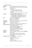
any modifications of this manual occur, the updated version will be available on ASRock website without further notice. You may find the latest memory and CPU support lists on ASRock website as well. ASRock website http://www.asrock.com 1.1 Package Contents ASRock P4VT8+ Motherboard (ATX Form Factor - ASRock P4VT8 | User Manual - Page 5
) Socket 478 for Intel® Pentium® 4 (Prescott, Northwood, Willimate) /Celeron® processor Chipsets: North Bridge: VIA PT800, FSB @ 800/533/400 MHz, with Hyper-Threading Technology ready South Bridge: VIA VT8237, supports USB 2.0, ATA 133, SATA 1.5Gb/s Memory: 3 DDR DIMM slots: DDR1, DDR2, and - ASRock P4VT8 | User Manual - Page 6
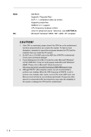
up events; Supports jumperfree; SMBIOS 2.3.1 support; CPU frequency stepless control (only for advanced users' reference, see CAUTION 4) Microsoft® Windows® 98SE / ME / 2000 / XP compliant CAUTION! 1. If the CPU is overheated, please check if the CPU fan on the motherboard functions properly before - ASRock P4VT8 | User Manual - Page 7
Out Mic In CD1 VIA PT800 Chipset 29 AUX1 7 28 AUDIO1 1 8 27 JL1 26 JR1 AGP1 9 25 Audio CODEC PCI 1 10 AGP 8X USB 2.0 VIA SATA2 11 24 LAN PHY PCI 2 VT8237 FSB800 DDR400 ATA133 5.1 CH SATA1 12 23 PCI 3 22 2MB BIOS Super I/O SATA PCI 4 P4VT8+ CMOS Battery CLRCMOS1 - ASRock P4VT8 | User Manual - Page 8
1.4 ASRock I/O PlusTM 1 11 10 9 1 Parallel Port 2 RJ-45 Port 3 Line In (Light Blue) 4 Line Out (Lime) 5 Microphone (Pink) 6 Shared USB 2.0 Ports (USB45) 2 3 4 5 8 7 6 7 USB 2.0 Ports (USB01) 8 USB 2.0 - ASRock P4VT8 | User Manual - Page 9
P4VT8+ is an ATX form factor (12.0-in x 7.5-in, 30.5 cm x 19.1 cm) motherboard. Before you install the motherboard, study the configuration of your chassis to ensure that the motherboard fits into it. Make sure to unplug the power cord before installing or removing the motherboard. Failure - ASRock P4VT8 | User Manual - Page 10
. Make sure that the CPU and the heatsink are securely fastened and in good contact with each other. Then connect the CPU fan to the CPU_FAN connector (CPU_FAN1, see page 7, No. 1). For proper installation, please kindly refer to the instruction manuals of the CPU fan and heatsink vendors. 10 - ASRock P4VT8 | User Manual - Page 11
2.5 Installation of Memory Modules (DIMM) P4VT8+ motherboard provides three 184-pin DDR (Double Data Rate) break The DIMM only fits in one correct orientation. It will cause permanent damage to the motherboard and the DIMM if you force the DIMM into the slot at incorrect orientation. Step 3. Firmly - ASRock P4VT8 | User Manual - Page 12
used to install a graphics card. The ASRock AGP slot has a special locking mechanism which can securely fasten the graphics card inserted. Do NOT use a 3.3V AGP card on the AGP slot of this motherboard. It may cause permanent damage! If you install Prescott 2.8G/533 CPU with Xabre600 VGA card, it is - ASRock P4VT8 | User Manual - Page 13
jumpers JL1 and JR1 are short, both the front panel and the rear panel audio connectors can work. CLRCMOS1 (see p.7 item 14) Clear CMOS 2-pin jumper system password, date, time, and system setup parameters. To clear and reset the system parameters to default setup, please turn off the computer and - ASRock P4VT8 | User Manual - Page 14
on this motherboard, please set the IDE device as "Master". Please refer to the instruction of your IDE CD-ROM to the secondary IDE connector (IDE2, black). Serial ATA Connectors (SATA1: see p.7 item 12) (SATA2: see p.7 item 11) SATA2 SATA1 These two Serial ATA (SATA) connectors support SATA - ASRock P4VT8 | User Manual - Page 15
(CD1: see p.7 item 30) (AUX1: see p.7 item 29) CD-L GND GND CD-R AUX-L GND GND AUX-R CD1 AUX1 These connectors allow you to receive stereo audio input from sound sources such as a CD-ROM, DVD-ROM, TV tuner card, or MPEG card. Front Panel Audio Connector (9-pin AUDIO1) (see p.7 item 28) GND +5VA - ASRock P4VT8 | User Manual - Page 16
1) (see p.7 item 16) PLED+ PLEDPWRBTN# GND 1 DUMMY RESET# GND HDLEDHDLED+ 1 SPEAKER DUMMY DUMMY +5V This connector accommodates several the fan cable to the connector matching the black wire to the ground pin. CPU Fan Connector (3-pin CPU_FAN1) (see p.7 item 1) CPU_FAN_SPEED +12V GND Connect - ASRock P4VT8 | User Manual - Page 17
and copy SATA HDD drivers. Once you have the SATA driver diskette ready, you may start to install Windows 2000 / Windows XP on your system directly without setting the RAID configuration on your system, or you may start to use VIA Tech RAID BIOS Utility to set RAID 0 / RAID 1 configuration before - ASRock P4VT8 | User Manual - Page 18
SCSI or Raid driver...." At this moment, please press key and follow the instructions of Windows 2000 or Windows XP for the proper installation. 2.9.2 RAID 0 / RAID 1 Configurations This motherboard adopts VIA VT8237 southbridge chipset that integrates RAID controller supporting RAID 0 and RAID - ASRock P4VT8 | User Manual - Page 19
2.9.2.1 Guide to Configure RAID 0 Please enter "VIA Tech RAID BIOS Utility" to set RAID 0 configuration. STEP 1: Boot-up your computer. STEP 2: During POST press key to enter "VIA Tech RAID BIOS Utility". STEP 3: Start the configuration from the option Create Array. Select the option Create - ASRock P4VT8 | User Manual - Page 20
configuration details in the Support CD. There are three instruction files to illustrate the three types of configurations step by step. 1. If you wish to install the SATA hard disks alone without making RAID setup, please refer to the file in the support CD: .. \ RAID SETUP \ SATA.PDF 2. If you - ASRock P4VT8 | User Manual - Page 21
use the BIOS Setup Utility to configure your system. The Flash Memory on the motherboard stores the BIOS Setup Utility. You may run the BIOS Setup Utility the predetermined choices. Because the BIOS software is constantly being updated, the following BIOS setup screens and descriptions are for - ASRock P4VT8 | User Manual - Page 22
Type Processor Speed Cache Size Microcode Update Total Memory DDR1 DDR2 DDR3 AMIBIOS SETUP UTILITY - VERSION 3.31a Security Power Boot Exit Jan 1 2004 Thu 10:07:40 [ Setup Help ] Month: Jan - Dec Day: 01 - 31 Year: 1980 - 2099 P4VT8+ BIOS P1.00 Pentium (R) 4 CPU 2400 MHz 512 KB F27 / 33 - ASRock P4VT8 | User Manual - Page 23
may due to that the hard disk is too old or too new. If the hard disk was already formatted on an older system, the BIOS Setup may detect incorrect parameters. In these cases, select [User] to manually enter the IDE hard disk drive parameters. After entering the hard disk information into - ASRock P4VT8 | User Manual - Page 24
for IDE CD/DVD drives. Capacity This field shows the drive's maximum capacity as calculated by the BIOS based on the drive information you entered. LBA Mode This allows user the LBA mode for a hard disk > 512 MB under DOS and Windows; for Netware and UNIX user, select [Off] to disable the LBA mode - ASRock P4VT8 | User Manual - Page 25
detects installed devices. Install the necessary drivers to activate the devices. 4.2.3 Utilities Menu The Utilities Menu shows the applications software that the motherboard supports. Click on a specific item then follow the installation wizard to install it. 4.2.4 ASRock PC-DIY Live Demo Program - ASRock P4VT8 | User Manual - Page 26
. CPU Ratio Selection: CPU Ratio is the multiple that times the frontside bus frequency will equal the core speed of the installed processor. Whether the option is open or locked is determined by the installed processor. DRAM Frequency: If [Auto] is selected, the motherboard will detect the memory - ASRock P4VT8 | User Manual - Page 27
enable or disable the use of USB controller. USB Device Legacy Support: Use this to enable or disable the support to emulate legacy I/O devices such as mouse, keyboard,... etc. DRAM CAS# Latency: This is used to adjust the means of memory accessing. Configuration options: [Auto], [2T], [2.5T], [3T - ASRock P4VT8 | User Manual - Page 28
to keep the default value unless the inserted PCI expansion cards' specifications require other settings. Primary Graphics Adapter: This allows you to Audio Auto Auto Disabled Auto ECP + EPP 1.9 Auto Auto Disabled 5 200h Enabled Enabled Auto to enable or disable the floppy drive controller. - ASRock P4VT8 | User Manual - Page 29
], [Auto] or [Enabled] for the onboard AC'97 Audio feature. System Hardware Monitor: You can check the status of the hardware on your system. It allows you to monitor the parameters for CPU temperature, Motherboard temperature, CPU fan speed, and critical voltage. Advanced AMIBIOS SETUP UTILITY - ASRock P4VT8 | User Manual - Page 30
p assword. Password Check: Select the check point for "Password Check". Configuration options: [Setup], [Always]. If [Setup] option is selected, the "Password Check" is performed before BIOS setup. If [Always] option is selected, the "Password Check" is performed before both boot-up and - ASRock P4VT8 | User Manual - Page 31
auto-detect or disable the Suspend-to-RAM feature. Select [Auto] will enable this feature if the system supports it. Repost Video on STR Resume: This feature allows you to repost video on STR resume. It is recommended to enable this feature under Microsoft® Windows® 98 / ME. Restore on AC/Power Loss - ASRock P4VT8 | User Manual - Page 32
Enter:Select Sub-Menu F9:Setup Defaults F10:Save & Exit Quick Boot Mode: Enable this mode will speed up the boot-up routine by skipping memory retestings. The default value is [Enabled]. Boot Up Num-Lock: If this is enabled, it will automatically activate the Numeric Lock function after boot-up - ASRock P4VT8 | User Manual - Page 33
[ Enter ] [ Setup Help ] Exits and saves the changes in CMOS RAM. F1:Help Esc:Exit :Select Item :Select Menu +/-:Change Values Enter:Select If you press , it will save the current settings and exit the BIOS SETUP Utility. Exit Discarding Changes: After you enter the submenu, the message "
-
 1
1 -
 2
2 -
 3
3 -
 4
4 -
 5
5 -
 6
6 -
 7
7 -
8
-
9
-
10
-
11
-
12
-
13
-
14
-
15
-
16
-
17
-
18
-
19
-
20
-
21
-
22
-
23
-
24
-
25
-
26
-
27
-
28
-
29
-
30
-
31
-
32
-
33
 |
 |
1
P4VT8+
User Manual
Version 1.0
Published January 2004
Copyright©2004 ASRock INC. All rights reserved.