ASRock P4i45PE User Manual
ASRock P4i45PE Manual
 |
View all ASRock P4i45PE manuals
Add to My Manuals
Save this manual to your list of manuals |
ASRock P4i45PE manual content summary:
- ASRock P4i45PE | User Manual - Page 1
P4i45PE+ User Manual Version 1.0 Published November 2003 Copyright©2003 ASRock INC. All rights reserved. 1 - ASRock P4i45PE | User Manual - Page 2
any form or by any means, except duplication of documentation by the purchaser for backup purpose, without written consent of ASRock Inc. Products and corporate names appearing in this manual may or may not be registered trademarks or copyrights of their respective companies, and are used only for - ASRock P4i45PE | User Manual - Page 3
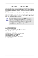
Package Contents 4 1.2 Specifications 5 1.3 Motherboard Layout 8 1.4 ASRock I/OTM 9 2 Installation 10 2.1 Screw Holes 10 2.2 Pre-installation Precautions 10 2.3 CPU Installation 11 2.4 Installation of CPU Fan and Heatsink 11 2.5 Installation of Memory Modules (DIMM 12 2.6 Expansion Slots - ASRock P4i45PE | User Manual - Page 4
modifications of this manual occur, the updated version will be available on ASRock website without further notice. You may find the latest memory and CPU support lists on ASRock website as well. ASRock website http://www.asrock.com 1.1 Package Contents ASRock P4i45PE+ Motherboard (ATX Form Factor - ASRock P4i45PE | User Manual - Page 5
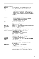
Floppy Port: Supports up to 2 floppy disk drives Audio: 5.1 channels AC'97 Audio PCI LAN: Speed: 802.3u (10/100 Ethernet), supports Wake-On-LAN Hardware Monitor: CPU temperature sensing (ASRock U-COP); Chassis temperature sensing; CPU overheat shutdown to protect CPU life (ASRock U-COP)(see - ASRock P4i45PE | User Manual - Page 6
: AMI legal BIOS; Supports "Plug and Play"; ACPI 1.1 compliance wake up events; Supports jumperfree; SMBIOS 2.3.1 support; CPU frequency stepless control (only for advanced users' reference, see CAUTION 6) Microsoft® Windows® 98 SE / ME / 2000 / XP compliant CAUTION! 1. P4i45PE+ motherboard may be - ASRock P4i45PE | User Manual - Page 7
below for the details. CPU FSB P4i45PE+ 800 MHz Configuration Note 1. Set the "FSB" jumper to "800" mode (see page 14). 2. Only support one DDR 400 memory module on DDR1 DIMM. (It does not support CL3 module.) The Recommended Memory Modules lists for P4i45PE+ motherboard. FSB 800 MHz / DDR - ASRock P4i45PE | User Manual - Page 8
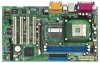
Motherboard AUDIO1 JR1 JL1 AUDIO CODEC Intel 845PE Chipset P4i45PE+ 1.5V_AGP1 IDE2 IDE1 PCI LAN Super I/O 2MB BIOS PCI 1 FSB800 17 16 1 FSB Select Jumper (FSB) 2 PS2_USB_PWR1 Jumper 3 CPU Heatsink Retention Module 4 CPU Socket 5 North Bridge Controller 6 184-pin DDR DIMM Slots ( - ASRock P4i45PE | User Manual - Page 9
1.4 ASRock I/OTM 1 2 3 10 9 8 1 Parallel Port 2 RJ-45 Port 3 Game Port 4 Microphone (Pink) 5 Line In (Light Blue) 7 65 4 6 Line Out (Lime) 7 USB 2.0 Ports 8 Serial Port (COM1) 9 PS/2 Keyboard Port (Purple) 10 PS/2 Mouse Port (Green) 9 - ASRock P4i45PE | User Manual - Page 10
P4i45PE+ is an ATX form factor (12.0-in x 7.0-in, 30.5 cm x 17.8 cm) motherboard. Before you install the motherboard, study the configuration of your chassis to ensure that the motherboard fits into it. Make sure to unplug the power cord before installing or removing the motherboard. Failure - ASRock P4i45PE | User Manual - Page 11
. Make sure that the CPU and the heatsink are securely fastened and in good contact with each other. Then connect the CPU fan to the CPU_FAN connector (CPU_FAN1, see page 8, No. 30). For proper installation, please kindly refer to the instruction manuals of the CPU fan and heatsink vendors - ASRock P4i45PE | User Manual - Page 12
2.5 Installation of Memory Modules (DIMM) P4i45PE+ motherboard provides two 184-pin DDR (Double Data Rate) break The DIMM only fits in one correct orientation. It will cause permanent damage to the motherboard and the DIMM if you force the DIMM into the slot at incorrect orientation. Step 3. Firmly - ASRock P4i45PE | User Manual - Page 13
P4i45PE+ motherboard. PCI slots: PCI slots are used to install expansion cards that have the 32-bit PCI interface. AGP slot: The AGP slot is used to install a graphics card. The ASRock MUST install the SATA driver before you install the USB 2.0 driver. Otherwise the system will not work properly. 13 - ASRock P4i45PE | User Manual - Page 14
pin2, pin3) is the setting for the over clocking of CPU frequency. PS2_USB_PWR1 1_2 2_3 Short pin2, pin3 to enable ( are short, both the front panel and the rear panel audio connectors can work. Clear CMOS (CLRCMOS0, 2-pin jumper) you just finish updating the BIOS, you must boot up the system - ASRock P4i45PE | User Manual - Page 15
one IDE device on this motherboard, please set the IDE device as "Master". Please refer to the instruction of your IDE device vendor for see p.8 item 21) SATA2 SATA1 These two Serial ATA (SATA) connectors support SATA data cables for internal storage devices. The current SATA interface allows up - ASRock P4i45PE | User Manual - Page 16
p.8 item 18) USB_PWR P-5 P+5 GND DUMMY 1 GND P+4 P-4 USB_PWR ASRock I/OTM provides you 4 default USB 2.0 ports on the rear panel. connector supports an optional wireless transmitting and receiving infrared module. These connectors allow you to receive stereo audio input from sound sources such - ASRock P4i45PE | User Manual - Page 17
Fan Connector (3-pin CHA_FAN1) (see p.8 item 12) CPU Fan Connector (3-pin CPU_FAN1) (see p.8 item 30) ATX motherboard adopts PCI SATA controller that supports Serial ATA (SATA) hard disks. You may install SATA hard disks on this motherboard for internal storage devices. This section will guide - ASRock P4i45PE | User Manual - Page 18
system while you only have SATA HDDs on your system, you will need to make an SATA driver diskette before you start the OS installation. STEP 1: STEP 2: STEP 3: STEP 4: STEP 5: Insert the ASRock Support CD into your optical drive to boot your system. (Do NOT insert any floppy diskette into the - ASRock P4i45PE | User Manual - Page 19
Setup Utility is designed to be user-friendly. It is a menu-driven program, which allows you to scroll through its various sub-menus and select among the predetermined choices. Because the BIOS software is constantly being updated, the following BIOS setup screens and descriptions are for reference - ASRock P4i45PE | User Manual - Page 20
Processor Type Processor Speed Cache Size Microcode Update Total Memory DDR1 DDR2 AMIBIOS SETUP UTILITY - VERSION 3.31a Security Power Boot Exit Nov 10 2003 Mon 16:07:40 [ Setup Help ] Month: Jan - Dec Day: 01 - 31 Year: 1980 - 2099 P4i45PE+ BIOS P2.30 Pentium (R) 4 CPU 2400 MHz 512 KB F24 / 18 - ASRock P4i45PE | User Manual - Page 21
may due to that the hard disk is too old or too new. If the hard disk was already formatted on an older system, the BIOS Setup may detect incorrect parameters. In these cases, select [User] to manually enter the IDE hard disk drive parameters. After entering the hard disk information into - ASRock P4i45PE | User Manual - Page 22
documentation to determine the correct value. Maximum Capacity This field shows the drive's maximum capacity as calculated by the BIOS based on the drive information you entered. LBA Mode This allows user to select the LBA mode for a hard disk > 512 MB under DOS and Windows; for Netware and UNIX - ASRock P4i45PE | User Manual - Page 23
detects installed devices. Install the necessary drivers to activate the devices. 4.2.3 Utilities Menu The Utilities Menu shows the applications software that the motherboard supports. Click on a specific item then follow the installation wizard to install it. 4.2.4 ASRock PC-DIY Live Demo Program - ASRock P4i45PE | User Manual - Page 24
CPU Ratio Selection CPU Ratio is the multiple that times the frontside bus frequency will equal the core speed of the installed processor. Whether the option is open or locked is determined by the installed processor. SDRAM Frequency If set to [Auto], the motherboard will detect the inserted memory - ASRock P4i45PE | User Manual - Page 25
[ Setup Help ] AGP Aperture Size ICH Delayed Transaction USB Controller USB Device Legacy Support 64MB Disabled Enabled Disabled to select the size of mapped memory for graphics data. CPU Thermal Throttling DRAM Write Throttling Enabled Enabled AGP / PCI Frequency Auto ******** DRAM - ASRock P4i45PE | User Manual - Page 26
Configure SDRAM Timing by SPD Select [Enabled] will configure the following 3 items by the contents in the SPD (Serial Presence Detect) device. SDRAM RAS# Precharge This controls the idle clocks after a precharge command is issued. SDRAM RAS# to CAS# Delay This controls the latency between the SDRAM - ASRock P4i45PE | User Manual - Page 27
Version Parallel Port IRQ Parallel Port DMA Channel OnBoard Midi Port Midi IRQ Select OnBoard Game Port OnBoard IDE OnBoard LAN OnBoard AC' 97 Audio Auto Auto Disabled Auto ECP + EPP 1.9 Auto Auto Disabled 5 200H Both Enabled Auto to enable or disable the floppy drive controller. F1:Help - ASRock P4i45PE | User Manual - Page 28
], [Auto] or [Disabled] for the on-board AC'97 Audio feature. System Hardware Monitor: You may check the status of the hardware on your system. It allows you to monitor the parameters for CPU temperature, Motherboard temperature, CPU fan speed, and critical voltage. Advanced AMIBIOS SETUP UTILITY - ASRock P4i45PE | User Manual - Page 29
current password first in order to create a new password. Set User Password Press to set User Password. Valid password can be a 1 to 6 alphanumeric Setup] option is selected, the "Password Check" is performed before BIOS setup. If [Always] option is selected, the "Password Check" is performed before - ASRock P4i45PE | User Manual - Page 30
field allows you to select whether to auto-detect or disable the ACPI Suspend-to-RAM feature. Select [Auto] will enable this feature if the system supports it. Repost Video on STR Resume This feature allows you to repost video on STR resume. It is recommended to enable this feature under Microsoft - ASRock P4i45PE | User Manual - Page 31
Enter:Select Sub-Menu F9:Setup Defaults F10:Save & Exit Quick Boot Mode Enable this mode will speed up the boot-up routine by skipping memory retestings. Boot Up Num-Lock Select [On] to activate the Numeric Lock function automatically after boot-up. Boot To OS/2 Select [Yes] to enable boot - ASRock P4i45PE | User Manual - Page 32
[ Enter ] [ Setup Help ] Exits and saves the changes in CMOS RAM. F1:Help Esc:Exit :Select Item :Select Menu +/-:Change Values Enter:Select If you press , it will save the current settings and exit the BIOS SETUP Utility. Exit Discarding Changes After you enter the submenu, the message "
-
 1
1 -
 2
2 -
 3
3 -
 4
4 -
 5
5 -
 6
6 -
 7
7 -
8
-
9
-
10
-
11
-
12
-
13
-
14
-
15
-
16
-
17
-
18
-
19
-
20
-
21
-
22
-
23
-
24
-
25
-
26
-
27
-
28
-
29
-
30
-
31
-
32
 |
 |

1
P4i45PE+
User Manual
Version 1.0
Published November 2003
Copyright©2003 ASRock INC. All rights reserved.