ASRock P4i945GC User Manual
ASRock P4i945GC Manual
 |
View all ASRock P4i945GC manuals
Add to My Manuals
Save this manual to your list of manuals |
ASRock P4i945GC manual content summary:
- ASRock P4i945GC | User Manual - Page 1
P4i945GC User Manual Version 1.0 Published June 2009 Copyright©2009 ASRock INC. All rights reserved. 1 - ASRock P4i945GC | User Manual - Page 2
without written consent of ASRock Inc. Products and corporate names appearing in this manual may or may not to infringe. Disclaimer: Specifications and information contained in this manual are furnished for informational on this motherboard contains Perchlorate, a toxic substance controlled in - ASRock P4i945GC | User Manual - Page 3
1 Introduction 5 1.1 Package Contents 5 1.2 Specifications 6 1.3 Motherboard Layout 9 1.4 ASRock 8CH I/O Plus 10 2 Installation 11 Pre-installation Precautions 11 2.1 CPU Installation 12 2.2 Installation of CPU Fan and Heatsink 12 2.3 Installation of Memory Modules (DIMM 13 2.4 Expansion - ASRock P4i945GC | User Manual - Page 4
4 Software Support 40 4.1 Install Operating System 40 4.2 Support CD Information 40 4.2.1 Running Support CD 40 4.2.2 Drivers Menu 40 4.2.3 Utilities Menu 40 4.2.4 Contact Information 40 4 - ASRock P4i945GC | User Manual - Page 5
guide to BIOS setup and information of the Support CD. Because the motherboard specifications and the BIOS software might be updated, the content of this manual will be subject to change without notice. In case any modifications of this manual occur, the updated version will be available on ASRock - ASRock P4i945GC | User Manual - Page 6
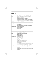
1.2 Specifications Platform CPU Chipset Memory Expansion Slot Graphics Audio LAN Rear Panel I/O Connector - Micro ATX Form Factor: 9.6-in x 7.7-in, 24.4 cm x 19.6 cm - Socket 478 for Intel® Pentium® 4 / Celeron® D (Prescott, Northwood) processors - FSB 800/533/400 MHz (see CAUTION 1) - Supports - ASRock P4i945GC | User Manual - Page 7
Wake Up Events - Supports jumperfree - AMBIOS 2.3.1 Support - Supports Smart BIOS Support CD - Drivers, Utilities, AntiVirus Software (Trial Version) Unique Feature - Instant Boot - ASRock Instant Flash (see CAUTION 10) - Hybrid Booster: - CPU Frequency Stepless Control (see CAUTION 11 - ASRock P4i945GC | User Manual - Page 8
hard disk to SATAII connector directly. 9. Power Management for USB 2.0 works fine under Microsoft® Windows® VistaTM / XP SP1 or SP2 / 2000 SP4. 10. ASRock Instant Flash is a BIOS flash utility embedded in Flash ROM. This convenient BIOS update tool allows you to update system BIOS without - ASRock P4i945GC | User Manual - Page 9
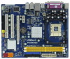
Header (USB6_7, Blue) 3 478-Pin CPU Socket 18 USB 2.0 Header (USB4_5, Blue) 4 CPU Heatsink Retention Module 19 System Panel Header (PANEL1, Orange) 5 2 x 240-pin DDR2 DIMM Slots 20 BIOS SPI Chip (Dual Channel: DDRII_1, DDRII_2; Yellow) 21 Floppy Connector (FLOPPY1) 6 ATX Power Connector - ASRock P4i945GC | User Manual - Page 10
1.4 I/O Panel 1 2 14 13 12 3 47 58 69 11 10 1 PS/2 Mouse Port (Green) 2 Parallel Port 3 RJ-45 Port 4 Side Speaker (Gray) 5 Rear Speaker (Black) 6 Central / Bass (Orange) 7 Line In (Light Blue) * 8 Front Speaker (Lime) 9 Microphone (Pink) 10 USB 2.0 Ports (USB01) 11 USB 2.0 Ports (USB23) 12 - ASRock P4i945GC | User Manual - Page 11
Chapter 2 Installation P4i945GC is a Micro ATX form factor (9.6-in x 7.7-in, 24.4 cm x 19.6 cm) motherboard. Before you install the motherboard, study the configuration of your chassis to ensure that the motherboard fits into it. Pre-installation Precautions Take note of the following precautions - ASRock P4i945GC | User Manual - Page 12
STEP 2/STEP 3: Match The CPU Marked Corner to The Socket Marked Corner STEP 4: Push Down And Lock The Socket Lever 2.2 Installation of CPU Fan and Heatsink This motherboard adopts 478-pin CPU socket to support Intel® Pentium®4 CPU. It requires larger heatsink and cooling fan to dissipate heat. You - ASRock P4i945GC | User Manual - Page 13
2.3 Installation of Memory Modules (DIMM) P4i945GC motherboard provides two 240-pin DDR2 (Double Data Rate 2) DIMM slots. Step 1. Step 2. 1. It is not allowed to install a DDR memory module into DDR2 slot; otherwise, this motherboard and DIMM may be damaged. 2. Please make sure to disconnect power - ASRock P4i945GC | User Manual - Page 14
There are 2 PCI slots and 2 PCI Express slots on this motherboard. PCI slots: PCI slots are used to install expansion cards that have VGA card to PCIE2 (PCIE x16 slot) and adjust the "Internal Graphics Mode Select" BIOS option to [Enabled, 1MB] or [Enabled, 8MB], the onboard VGA will be enabled, - ASRock P4i945GC | User Manual - Page 15
5 seconds. FD Jumpers (FD0 3-pin jumper, see p.9 No. 29) (FD2 3-pin jumper, see p.9 No. 28) 1_2 1_2 Default Note: If you want to adopt FSB400-CPU on this motherboard, you need to adjust the jumpers. Please short pin2, pin3 for FD0 jumper and pin2, pin3 for FD2 jumper. Otherwise, the - ASRock P4i945GC | User Manual - Page 16
one IDE device on this motherboard, please set the IDE device as "Master". Please refer to the instruction of your IDE device SATAII_4: see p.9, No. 12) These Serial ATAII (SATAII) connectors support SATAII or SATA hard disk for internal storage devices. The current SATAII interface allows up to - ASRock P4i945GC | User Manual - Page 17
USB 2.0 headers on this motherboard. Each USB 2.0 header can support two USB 2.0 ports. control of audio devices. 1. High Definition Audio supports Jack Sensing, but the panel wire on the chassis must support HDA to function correctly. Please follow the instruction in our manual and chassis manual - ASRock P4i945GC | User Manual - Page 18
of "Playback" portion. For Windows® VistaTM OS: Go to the "Front Mic" Tab in the Realtek Control panel. Click "Set Default fan cable to this connector and match the black wire to the ground pin. CPU Fan Connector (3-pin CPU_FAN1) (see p.9 No. 2) GND +12V CPU_FAN_SPEED Please connect a CPU fan - ASRock P4i945GC | User Manual - Page 19
(see p.9, No. 6) 12 24 Please connect an ATX power supply to this connector. 1 13 Though this motherboard provides 24-pin ATX power connector, 12 24 it can still work if you adopt a traditional 20-pin ATX power supply. To use the 20-pin ATX power supply, please plug your power supply along - ASRock P4i945GC | User Manual - Page 20
disk setup guide. Some default setting of SATAII hard disks may not be at SATAII mode, which operate with the best performance. In order to enable SATAII function, please follow the below instruction support/download.htm The above examples are just for your reference. For different SATAII hard disk - ASRock P4i945GC | User Manual - Page 21
Serial ATA (SATA) / Serial ATAII (SATAII) Hard Disks Installation This motherboard adopts Intel® ICH7 south bridge chipset that supports Serial ATA (SATA) / Serial ATAII (SATAII) hard disks. You may install SATA / SATAII hard disks on this motherboard for internal storage devices. This section will - ASRock P4i945GC | User Manual - Page 22
the BIOS SETUP UTILITY to configure your system. The BIOS FWH chip on the motherboard stores the BIOS SETUP UTILITY. You may run the BIOS SETUP off and then back on. Because the BIOS software is constantly being updated, the following BIOS setup screens and descriptions are for reference purpose - ASRock P4i945GC | User Manual - Page 23
:09] [Wed 06/10/2009] BIOS Version : P4i945GC P1.00 Processor Type : Intel (R) Celeron (R) CPU 2.60GHz Processor Speed : 2600MHz Microcode Update : F29/2E Cache Size : 128KB Total Memory DDRII1 DDRII2 : 512MB with 8MB shared memory Single-Channel Memory Mode : 512MB/200MHz (DDRII400) : None - ASRock P4i945GC | User Manual - Page 24
Flash ASRock Instant Flash is a BIOS flash utility embedded in Flash ROM. This convenient BIOS update tool allows you to update system BIOS without entering operating systems first like MS-DOS or Windows®. Just launch this tool and save the new BIOS file to your USB flash drive, floppy disk or - ASRock P4i945GC | User Manual - Page 25
2005, American Megatrends, Inc. Setting wrong values in this section may cause the system to malfunction. 3.4.1 CPU Configuration BIOS SETUP UTILITY Advanced CPU Configuration Overclock Mode CPU Frequency (MHz) PCIE Frequency (MHz) Boot Failure Guard Spread Spectrum [Auto] [100] [100] [Enabled - ASRock P4i945GC | User Manual - Page 26
of this motherboard. Max CPUID Value Limit For Prescott CPU only, some Intel Pentium® 4 processor that supports Hyper-Threading technology and an operating system that includes optimization for this technology, such as Microsoft® Windows® XP. Set to [Enabled] if using Microsoft® Windows® XP, or Linux - ASRock P4i945GC | User Manual - Page 27
is selected, the motherboard will detect the memory module(s) inserted and CPU you adopt. Flexibility Option The default value of this option is [Disabled]. It will allow better tolerance for memory [6 DRAM Clocks]. DRAM RAS# Precharge This controls the idle clocks after a precharge command is - ASRock P4i945GC | User Manual - Page 28
is [Auto]. Configuration options: [Auto] and [Manual]. Primary Graphics Adapter This item shows the primary Windows® VistaTM OS because the driver will intelligently detect physical memory available and allocate necessary video memory. DVMT/FIXED Memory You are allowed to adjust the shared memory - ASRock P4i945GC | User Manual - Page 29
OnBoard Lan This allows you to enable or disable the "OnBoard Lan" feature. DRAM Voltage Use this to select DRAM Voltage. Configuration options: [Auto], [1.794V], [1.851V], [1.908V], [1.965V], [2.029V], [2.086V], [2.144V] and [2.201V]. The default value of this feature is [Auto]. +1.5V Voltage Use - ASRock P4i945GC | User Manual - Page 30
3.4.3 ACPI Configuration BIOS SETUP UTILITY Advanced ACPI Configuration Suspend To RAM Restore on AC auto-detect or disable the Suspend-toRAM feature. Select [Auto] will enable this feature if the OS supports it. If you set this item to [Disabled], the function "Repost Video on STR Resume" will be - ASRock P4i945GC | User Manual - Page 31
motherboard to submit Windows® VistaTM certification. 3.4.4 IDE Configuration BIOS SETUP UTILITY Advanced IDE Configuration SATAII/IDE1 Configuration OnBoard IDE2 Controller will not work. Because Intel® ICH7 south bridge only supports four IDE devices under legacy OS (Windows® NT), you have to - ASRock P4i945GC | User Manual - Page 32
as the example in the following instruction, which can be applied to "SATAII 4" as well. BIOS SETUP UTILITY Advanced Primary IDE Disk :ST340014A :40.0 GB :Supported :16Sectors :4 :MultiWord DMA-2 :Ultra DMA-5 :Supported a hard disk > 512 MB under DOS and Windows; for Netware and UNIX user, select - ASRock P4i945GC | User Manual - Page 33
disk performance by optimizing the hard disk timing. DMA Mode DMA capability allows the improved transfer-speed maximize the IDE hard disk data transfer rate. 3.4.5 PCIPnP Configuration BIOS SETUP UTILITY Advanced Advanced PCI expansion cards' specifications require other settings. PCI IDE - ASRock P4i945GC | User Manual - Page 34
configure the type of your floppy drive. BIOS SETUP UTILITY Advanced Floppy Configuration Floppy A [1.44 MB 312"] Select the type of floppy drive DMA Channel Parallel Port IRQ [Enabled] [3F8 / IRQ4] [378] [ECP + EPP] [1.9] [DMA3] [IRQ7] Allow BIOS to Enable or Disable Floppy Controller. +F1 - ASRock P4i945GC | User Manual - Page 35
ECP mode DMA channel. Configuration options: [DMA0], [DMA1], and [DMA3]. Parallel Port IRQ Use this item to set the IRQ for the parallel port. Configuration options: [IRQ5] and [IRQ7]. 3.4.8 USB Configuration BIOS SETUP UTILITY Advanced USB Configuration USB Controller USB 2.0 Support Legacy USB - ASRock P4i945GC | User Manual - Page 36
to use only under BIOS setup and Windows / Linux OS. 3.5 Hardware Health Event Monitoring Screen In this section, it allows you to monitor the status of the hardware on your system, including the parameters of the CPU temperature, motherboard temperature, CPU fan speed, chassis fan speed, and the - ASRock P4i945GC | User Manual - Page 37
you to configure the boot settings and the boot priority. BIOS SETUP UTILITY Main Smart Advanced H/W Monitor Boot Security Exit Boot Boot. 1st Boot Device 2nd Boot Device 3rd Boot Device 4th Boot Device Hard Disk Drives Removable Drives CD/DVD Drives [1st Floppy Device] [HDD: PM - HDS722580VL - ASRock P4i945GC | User Manual - Page 38
you may set or change the supervisor/user password for the system. For the user password, you may also clear it. BIOS SETUP UTILITY Main Smart Advanced H/W Monitor Boot Security Exit Security Settings Supervisor Password : Not Installed User Password : Not Installed Change Supervisor Password - ASRock P4i945GC | User Manual - Page 39
3.8 Exit Screen BIOS SETUP UTILITY Main Smart Advanced H/W Monitor Boot Security Exit Exit Options Save Changes and Exit Discard Changes and Exit Discard Changes Would you like to save current setting user defaults ? Save 1st User Defaults Load 1st User Defaults Save 2nd User Defaults Load 2nd - ASRock P4i945GC | User Manual - Page 40
install the necessary drivers to activate the devices. 4.2.3 Utilities Menu The Utilities Menu shows the applications software that the motherboard supports. Click on a specific item then follow the installation wizard to install it. 4.2.4 Contact Information If you need to contact ASRock or want to
-
 1
1 -
 2
2 -
 3
3 -
 4
4 -
 5
5 -
 6
6 -
 7
7 -
8
-
9
-
10
-
11
-
12
-
13
-
14
-
15
-
16
-
17
-
18
-
19
-
20
-
21
-
22
-
23
-
24
-
25
-
26
-
27
-
28
-
29
-
30
-
31
-
32
-
33
-
34
-
35
-
36
-
37
-
38
-
39
-
40
 |
 |

1
P4i945GC
User Manual
Version 1.0
Published June 2009
Copyright©2009 ASRock INC. All rights reserved.