ASRock P4i945GC Quick Installation Guide - Page 2
Motherboard L, ayout - fan control
 |
View all ASRock P4i945GC manuals
Add to My Manuals
Save this manual to your list of manuals |
Page 2 highlights
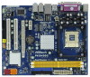
Motherboard Layout English 1 PS2_USB_PWR1 Jumper 16 Chassis Speaker Header (SPEAKER 1, Purple) 2 CPU Fan Connector (CPU_FAN1) 17 USB 2.0 Header (USB6_7, Blue) 3 478-Pin CPU Socket 18 USB 2.0 Header (USB4_5, Blue) 4 CPU Heatsink Retention Module 19 System Panel Header (PANEL1, Orange) 5 2 x 240-pin DDR2 DIMM Slots 20 BIOS SPI Chip (Dual Channel: DDRII_1, DDRII_2; Yellow) 21 Floppy Connector (FLOPPY1) 6 ATX Power Connector (ATXPWR1) 22 Front Panel Audio Header 7 Secondary IDE Connector (IDE2, Black) (HD_AUDIO1, Lime) 8 Primary IDE Connector (IDE1, Blue) 23 PCI Slots (PCI1- 2) 9 Clear CMOS Jumper (CLRCMOS1) 24 Internal Audio Connector: CD1 (Black) 10 South Bridge Controller 25 PCI Express x16 Slot (PCIE2) 11 Third SATAII Connector (SATAII_3; Orange) 26 PCI Express x1 Slot (PCIE1) 12 Fourth SATAII Connector (SATAII_4; Orange) 27 North Bridge Controller 13 Secondary SATAII Connector (SATAII_2; Red) 28 FD2 Jumper 14 Primary SATAII Connector (SATAII_1; Red) 29 FD0 Jumper 15 Chassis Fan Connector (CHA_FAN1) 30 ATX 12V Connector (ATX12V1) 2 ASRock P4i945GC Motherboard
-
 1
1 -
 2
2 -
 3
3 -
 4
4 -
 5
5 -
 6
6 -
 7
7 -
 8
8 -
9
-
10
-
11
-
12
-
13
-
14
-
15
-
16
-
17
-
18
-
19
-
20
-
21
-
22
-
23
-
24
-
25
-
26
-
27
-
28
-
29
-
30
-
31
-
32
-
33
-
34
-
35
-
36
-
37
-
38
-
39
-
40
-
41
-
42
-
43
-
44
-
45
-
46
-
47
-
48
-
49
-
50
-
51
-
52
-
53
-
54
-
55
-
56
-
57
-
58
-
59
-
60
-
61
-
62
-
63
-
64
-
65
-
66
-
67
-
68
-
69
-
70
-
71
-
72
 |
 |
