ASRock P55 Pro Quick Installation Guide
ASRock P55 Pro Manual
 |
View all ASRock P55 Pro manuals
Add to My Manuals
Save this manual to your list of manuals |
ASRock P55 Pro manual content summary:
- ASRock P55 Pro | Quick Installation Guide - Page 1
by ASRock. ASRock assumes no responsibility for any errors or omissions that may appear in this guide. With respect to the contents of this guide, ASRock ASRock Website: http://www.asrock.com Published August 2009 Copyright©2009 ASRock INC. All rights reserved. 1 ASRock P55 Pro Motherboard English - ASRock P55 Pro | Quick Installation Guide - Page 2
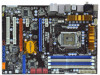
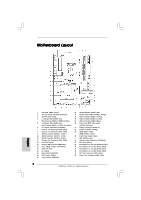
(CHA_FAN3) 13 Intel P55 Chipset 14 Primary IDE Connector (IDE1, Blue) 15 Clear CMOS Jumper (CLRCMOS1) 16 16Mb SPI Flash 17 Dr. Debug 18 Reset Switch (RSTBTN) 19 36 PCI Express 2.0 x1 Slot (PCIE1, White) 37 CPU Fan Connector (CPU_FAN1) 38 Power Fan Connector (PWR_FAN1) 2 ASRock P55 Pro Motherboard - ASRock P55 Pro | Quick Installation Guide - Page 3
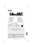
13 14 15 16 17 18 Front Speaker (Lime) Microphone (Pink) USB 2.0 Ports (USB45) USB 2.0 Ports (USB23) USB 2.0 Ports (USB01) Powered eSATAII/USB Connector Optical SPDIF Out Port Clear CMOS Switch (CLRCBTN) PS/2 Keyboard Audio 2nd output" to use front panel audio. 3 ASRock P55 Pro Motherboard English - ASRock P55 Pro | Quick Installation Guide - Page 4
introduction of the motherboard and step-by-step installation guide. More detailed information of the motherboard can be found in the user manual presented in the Support CD. Because the motherboard specifications and the BIOS software might be updated, the content of this manual will be subject - ASRock P55 Pro | Quick Installation Guide - Page 5
i5 Processors in the LGA1156 Package - Advanced V8 + 2 Power Phase Design - Supports Intel® Turbo Boost Technology - Supports Hyper-Threading Technology (see CAUTION 1) - Supports Untied Overclocking Technology (see CAUTION 2) - Supports EM64T CPU - Intel® P55 - Dual Channel DDR3 Memory Technology - ASRock P55 Pro | Quick Installation Guide - Page 6
jumperfree - SMBIOS 2.3.1 Support - CPU, VCCM, SB, VTT, VCCM REF, PCH_PLL Voltage Multi-adjustment - Supports I. O. T. (Intelligent Overclocking Technology) English - Supports Smart BIOS Support CD - Drivers, Utilities, AntiVirus Software (Trial Version) Unique Feature - ASRock OC Tuner - ASRock P55 Pro | Quick Installation Guide - Page 7
1600 is supported through overclocking. 6. For microphone input, this motherboard supports both stereo and mono modes. For audio output, this motherboard supports 2-channel, 4-channel, 6-channel, and 8-channel modes. Please check the table on page 3 for proper connection. English 7 ASRock P55 Pro - ASRock P55 Pro | Quick Installation Guide - Page 8
provides the flexible option to adopt two different CPU cooler types, Socket LGA 775 and LGA 1156. Please be noticed that not all the 775 CPU Fan can be used. 15. EuP, standard, an EuP ready motherboard and an EuP ready power supply are required. According to 8 ASRock P55 Pro Motherboard English - ASRock P55 Pro | Quick Installation Guide - Page 9
with * mark are supported under Windows® VistaTM / VistaTM 64-bit only. * For the latest updates of the supported PCI Express VGA card list for CrossFireXTM Mode, please visit our website for details. ASRock website: http://www.asrock.com/support/index.htm English 9 ASRock P55 Pro Motherboard - ASRock P55 Pro | Quick Installation Guide - Page 10
Before you insert the 1156-Pin CPU into the socket, please check if the CPU surface is unclean or if there is any bent pin on the socket. Do not force to insert the CPU into the socket if above situation is found. Otherwise, the CPU will be seriously damaged. 10 ASRock P55 Pro Motherboard English - ASRock P55 Pro | Quick Installation Guide - Page 11
if returning the motherboard for after service. Step 3. Insert the 1156-Pin CPU: Step 3-1. Hold the CPU by the 1156-Pin Socket 1156-Pin CPU For proper inserting, please ensure to match the two orientation key notches of the CPU with the two alignment keys of the socket. ASRock P55 Pro Motherboard - ASRock P55 Pro | Quick Installation Guide - Page 12
other components. Please be noticed that this motherboard supports Combo Cooler Option (C.C.O.), which provides the flexible option to adopt two different CPU cooler types, Socket LGA 775 and LGA 1156. The white throughholes are for Socket LGA 1156 CPU fan. 12 ASRock P55 Pro Motherboard English - ASRock P55 Pro | Quick Installation Guide - Page 13
the Dual Channel Memory Technology. 3. It is not allowed to install a DDR or DDR2 memory module into DDR3 slot;otherwise, this motherboard and DIMM may be damaged. 4. Please install the memory module into the white slot (DDR3_B1) for the first priority. English 13 ASRock P55 Pro Motherboard - ASRock P55 Pro | Quick Installation Guide - Page 14
. It will cause permanent damage to the motherboard and the DIMM if you force the DIMM into the slot at incorrect orientation. Step 3. Firmly insert the DIMM into the slot until the retaining clips at both ends fully snap back in place and the DIMM is properly seated. 14 ASRock P55 Pro Motherboard - ASRock P55 Pro | Quick Installation Guide - Page 15
is used for PCI Express x16 lane width graphics cards, or used to install PCI Express graphics cards to support CrossFireXTM function. PCIE4 (PCIE x16 slot; Orange) is used for PCI Express x1 lane width cards, such with screws. Step 6. Replace the system cover. 15 ASRock P55 Pro Motherboard English - ASRock P55 Pro | Quick Installation Guide - Page 16
in the future, please refer to ATITM graphics card manuals for detailed installation guide. Step 1. Insert one Radeon graphics card into PCIE2 slot and the other Radeon graphics card to PCIE4 slot. Make sure that the cards are properly seated on the slots. 16 ASRock P55 Pro Motherboard English - ASRock P55 Pro | Quick Installation Guide - Page 17
is provided with the graphics card you purchase, not bundled with this motherboard. Please refer to your graphics card vendor for details.) CrossFire Bridge or Step 2. Connect the DVI monitor cable to the DVI Sub monitor cable to the DVI to D-Sub adapter.) English 17 ASRock P55 Pro Motherboard - ASRock P55 Pro | Quick Installation Guide - Page 18
drivers prior to installation. Please check AMD website for ATITM driver updates. Step 3. Step 4. Step 5. Install the required drivers to your system. For Windows® XP OS: A. ATITM recommends Windows® XP Service on the Radeon graphics cards. Click "Apply". English 18 ASRock P55 Pro Motherboard - ASRock P55 Pro | Quick Installation Guide - Page 19
for identification or explanation and to the owners' benefit, without intent to infringe. * For further information of ATITM CrossFireXTM technology, please check AMD website for updates and details. 19 ASRock P55 Pro Motherboard English - ASRock P55 Pro | Quick Installation Guide - Page 20
on CLRCMOS1 for 5 seconds. However, please do not clear the CMOS right after you update the BIOS. If you need to clear the CMOS when you just finish updating the BIOS, you must boot up the system first, and then shut it down before you do the clearCMOS action. English 20 ASRock P55 Pro Motherboard - ASRock P55 Pro | Quick Installation Guide - Page 21
instruction of your IDE device vendor for the details. Serial ATAII Connectors (SATAII_1_2: see p.2, No. 9) (SATAII_3_4: see p.2, No. 10) (SATAII_5_6: see p.2, No. 11) These six Serial ATAII (SATAII) connectors support disk or the SATAII connector on this motherboard. 21 ASRock P55 Pro Motherboard - ASRock P55 Pro | Quick Installation Guide - Page 22
supply. Besides six default USB 2.0 ports on the I/O panel, there are three USB 2.0 headers on this motherboard. Each USB 2.0 header can support two USB 2.0 ports. (9-pin USB8_9 . This header supports an optional wireless transmitting and receiving infrared module. 22 ASRock P55 Pro Motherboard - ASRock P55 Pro | Quick Installation Guide - Page 23
supports Jack Sensing, but the panel wire on the chassis must support HDA to function correctly. Please follow the instruction in our manual and chassis manual . E. Enter BIOS Setup Utility. Enter Advanced Settings, and then select Chipset Configuration. Set ASRock P55 Pro Motherboard English - ASRock P55 Pro | Quick Installation Guide - Page 24
motherboard provides 24-pin ATX power connector, 12 24 it can still work if you adopt a traditional 20-pin ATX power supply. To use the 20-pin ATX power supply, please plug your power supply along with Pin 1 and Pin 13. 20-Pin ATX Power Supply Installation 1 13 24 ASRock P55 Pro Motherboard - ASRock P55 Pro | Quick Installation Guide - Page 25
there is one IEEE 1394 header (FRONT_1394) on this motherboard. This IEEE 1394 header can support one IEEE 1394 port. This COM1 header supports a serial port module. HDMI_SPDIF Header (3-pin HDMI_SPDIF1) ( connector of HDMI VGA card to this header. 25 ASRock P55 Pro Motherboard English - ASRock P55 Pro | Quick Installation Guide - Page 26
switch, allowing users to quickly turn on/off the system. Reset Switch (RSTBTN) (see p.2 No. 18) Reset Switch is a smart switch, allowing users to quickly reset the system. Clear CMOS Switch (CLRCBTN) (see p.3 No 20 "Clear CMOS jumper" description instead. English 26 ASRock P55 Pro Motherboard - ASRock P55 Pro | Quick Installation Guide - Page 27
the Uncompressed pointer for future use in PMM. Copying Main BIOS into memory. Leaves all RAM below 1MB Read-Write including E000 and F000 shadow areas but closing SMRAM. Restore CPUID value back into register. Give control to BIOS POST (ExecutePOSTKernel). English 27 ASRock P55 Pro Motherboard - ASRock P55 Pro | Quick Installation Guide - Page 28
video adapter installed in the system that have optional ROMs. Initializes all the output devices. Allocate memory for ADM module and uncompress it. Give control to ADM module for initialization. Initialize language and font modules for ADM. Activate ADM module. ASRock P55 Pro Motherboard English - ASRock P55 Pro | Quick Installation Guide - Page 29
AA Uninstall POST INT1Ch vector and INT09h vector. Deinitializes the ADM module. AB Prepare BBS for Int 19 boot. AC End of POST initialization of chipset registers. B1 Save system context for ACPI. 00 Passes control to OS Loader (typically INT19h). English 29 ASRock P55 Pro Motherboard - ASRock P55 Pro | Quick Installation Guide - Page 30
below steps. Using SATA / SATAII HDDs without NCQ function STEP 1: Set up BIOS. A. Enter BIOS SETUP UTILITY Advanced screen Storage Configuration. B. Set the option "SATAII Operation Mode" to [IDE]. STEP 2: Install Windows® XP / XP 64-bit OS on your system. 30 ASRock P55 Pro Motherboard English - ASRock P55 Pro | Quick Installation Guide - Page 31
during overclocking, but PCI / PCIE buses are in the fixed mode so that FSB can operate under a more stable overclocking environment. Please refer to the warning on page 7 for the possible overclocking risk before you apply Untied Overclocking Technology. 31 ASRock P55 Pro Motherboard English - ASRock P55 Pro | Quick Installation Guide - Page 32
detailed information about BIOS Setup, please refer to the User Manual (PDF file) contained in the Support CD. 4. Software Support CD information This motherboard supports various Microsoft® EXE" from the BIN folder in the Support CD to display the menus. 32 ASRock P55 Pro Motherboard English - ASRock P55 Pro | Quick Installation Guide - Page 33
Modell benötigen, besuchen Sie bitte unsere Webseite: www.asrock.com/support/index.asp 1.1 Kartoninhalt ASRock P55 Pro Motherboard (ATX-Formfaktor: 30.5 cm x 21.8 cm; 12.0 Zoll x 8.6 Zoll) ASRock P55 Pro Schnellinstallationsanleitung ASRock P55 Pro Support-CD Ein 80-adriges Ultra-ATA 66/100/133 IDE - ASRock P55 Pro | Quick Installation Guide - Page 34
EM64T-CPU - Intel® P55 - Unterstützung von Dual-Kanal-Speichertechnologie (siehe VORSICHT 3) - 4 x Steckplätze für DDR3 - Unterstützt DDR3 2600+(OC x PS/2-Tastaturanschluss - 1 x Koaxial-SPDIF-Ausgang - 1 x optischer SPDIF-Ausgang - 6 x Standard-USB 2.0-Anschlüsse ASRock P55 Pro Motherboard Deutsch - ASRock P55 Pro | Quick Installation Guide - Page 35
ützen RAID(RAID 0, RAID 1, RAID 10, RAID 5 und Intel Matrix Storage BIOS - Treiber, Dienstprogramme, Antivirussoftwar (Probeversion) - ASRock OC Tuner (siehe VORSICHT 9) - Intelligent Energy Saver (Intelligente Energiesparfunktion) (siehe VORSICHT 10) - Sofortstart 35 ASRock P55 Pro Motherboard - ASRock P55 Pro | Quick Installation Guide - Page 36
Informationen. 3. Dieses Motherboard unterstützt Dual-Kanal-Speichertechnologie. Vor Implementierung der Dual-Kanal-Speichertechnologie müssen Sie die Installationsanleitung für die Speichermodule auf Seite 43 zwecks richtiger Installation gelesen haben. 36 ASRock P55 Pro Motherboard Deutsch - ASRock P55 Pro | Quick Installation Guide - Page 37
Ihr BIOS mit nur wenigen Klickvorgängen ohne Bereitstellung einer zusätzlichen Diskette oder eines anderen komplizierten Flash-Programms aktualisieren. Achten Sie darauf, dass das USB-Flash-Laufwerk oder die Festplatte das Dateisystem FAT32/16/12 benutzen muss. 37 ASRock P55 Pro Motherboard Deutsch - ASRock P55 Pro | Quick Installation Guide - Page 38
zwei verschiedenen CPU-Kühlertypen, Socket LGA 775 und LGA 1156. Beachten Sie bitte, dass nicht alle 775 CPU-Lüfter verwendet EuP-fähiges Motherboard und eine EuP-fähige Stromversorgung erforderlich. Gemäß einer Empfehlung von Intel muss eine EuP abzufragen. 38 ASRock P55 Pro Motherboard Deutsch - ASRock P55 Pro | Quick Installation Guide - Page 39
) 1156-Pin Sockel Übersicht Bevor Sie die 1156-Pin CPU in den Sockel sitzen, prüfen Sie bitte, ob die CPU-Oberfläche sauber ist und keine der Kontakte verbogen sind. Setzen Sie die CPU nicht mit Gewalt in den Sockel, dies kann die CPU schwer beschädigen. Deutsch 39 ASRock P55 Pro Motherboard - ASRock P55 Pro | Quick Installation Guide - Page 40
mit dem IHS (Integrated Heat Sink - integrierter Kühlkörper) nach oben. Suchen Sie Pin 1 und die zwei Orientierungseinkerbungen. Orientierungskerbe Ausrichtungsmarkierung Pin1 Pin1 Ausrichtungsmarkierung 40 Orientierungskerbe 1156-Pin CPU 1156-Pin Sockel ASRock P55 Pro Motherboard - ASRock P55 Pro | Quick Installation Guide - Page 41
. Schritt 3-3. Drücken Sie die CPU vorsichtig in vertikaler Richtung in den Sockel. Schritt 3-4. Prüfen Sie, dass die CPU ordnungsgemäß im Sockel sitzt und die Ladehebel. Schritt 4-3. Sichern Sie Ladehebel und Ladeplatte mithilfe des Hebelverschlusses. 41 ASRock P55 Pro Motherboard Deutsch - ASRock P55 Pro | Quick Installation Guide - Page 42
, dass dieses Motherboard die ComboKühleroption unterstützt, die eine flexible Möglichkeit zur Aufnahme von zwei verschiedenen CPU-Kühlertypen, Socket LGA 775 und LGA 1156, bietet. Das weiße Durchgangsloch ist für den CPULüfter im Socket LGA 1156 vorgesehen. 42 ASRock P55 Pro Motherboard Deutsch - ASRock P55 Pro | Quick Installation Guide - Page 43
nicht aktivieren. 3. Es ist nicht zulässig, DDR oder DDR2 in einen DDR3 Steckplatz zu installieren; andernfalls könnten Motherboard und DIMMs beschädigt werden. 4. Installieren Sie das Speichermodul für die erste Priorität im weißen Steckplatz (DDR3_B1). Deutsch 43 ASRock P55 Pro Motherboard - ASRock P55 Pro | Quick Installation Guide - Page 44
in die Steckplätze, so dass die Halteklammern an beiden Enden des Moduls einschnappen und das DIMM-Modul fest an Ort und Stelle sitzt. 44 ASRock P55 Pro Motherboard - ASRock P55 Pro | Quick Installation Guide - Page 45
-Steckplätze) Es gibt einen 2 PCI-Steckplätze und 4 PCI Express-Steckplätze am P55 Pro Motherboard. PCI-Slots: PCI-Slots werden zur Installation von Erweiterungskarten mit dem 32bit PCI-Interface genutzt. 4: Befestigen Sie die Karte mit der Schraube aus Schritt 2. 45 ASRock P55 Pro Motherboard - ASRock P55 Pro | Quick Installation Guide - Page 46
von den Betriebssystemen Windows® XP mit Service Pack 2 und VistaTM unterstützt. Updates gibt. Beachten Sie den detailliert erklärten Installationsablauf auf Seite 16. 2.6 "Surround Display" Dieses Motherboard Support-CD: ..\ Surround Display Information 46 ASRock P55 Pro Motherboard Deutsch - ASRock P55 Pro | Quick Installation Guide - Page 47
- No. 1) +5VSB (Standby) zu setzen und die PS/2 oder USB- Weckfunktionen zu aktivieren. Hinweis: Um +5VSB nutzen zu können, muss das BIOS löschen müssen, müssen Sie zuerst das System starten und dann wieder ausschalten, bevor Sie den CMOS-Inhalt löschen. Deutsch 47 ASRock P55 Pro Motherboard - ASRock P55 Pro | Quick Installation Guide - Page 48
Header und Anschlüsse. Wenn Sie Jumperkappen auf Header und Anschlüsse setzen, wird das Motherboard unreparierbar beschädigt! Anschluss für das Floppy-Laufwerk (33-Pin FLOPPY1) (siehe S.2 - das SATAII Verbindungsstück auf dieser Hauptplatine angeschlossen werden. 48 ASRock P55 Pro Motherboard - ASRock P55 Pro | Quick Installation Guide - Page 49
Zusätzlich zu den sechs üblichen USB 2.0-Ports an den I/O-Anschlüssen befinden sich drei USB 2.0Anschlussleisten am Motherboard. Pro USB 2.0Anschlussleiste werden zwei USB 2.0-Ports unterstützt. (9-pol. USB8_9 ein optionales, drahtloses Sendeund Empfangs-Infrarotmodul. 49 ASRock P55 Pro Motherboard - ASRock P55 Pro | Quick Installation Guide - Page 50
angeschlossen werden. E. Rufen Sie das BIOS-Setup-Dienstprogramm auf. Wechseln Sie zu Erweiterte Einstellungen und wählen Sie Chipset-Konfiguration. Setzen Sie die Option Frontleistenkontrolle von Möchten Sie Ihre Stimme über das vorderseitige Mikrofon hören, dann 50 ASRock P55 Pro Motherboard - ASRock P55 Pro | Quick Installation Guide - Page 51
auch ohne Geschwindigkeitsregulierung. Wenn Sie einen dreipoligen CPU-Lüfter an den CPU-Lüferanschluss dieses Motherboards anschließen möchten, verbinden Sie ihn bitte mit den Pins 1 - 3. Pins 1-3 anschließen Lüfter mit dreipoligem Anschluss installieren Deutsch 51 ASRock P55 Pro Motherboard - ASRock P55 Pro | Quick Installation Guide - Page 52
- No. 6) 12 24 Verbinden Sie die ATXStromversorgung mit diesem Header. 1 13 Obwohl dieses Motherboard einen 24-pol. ATX-Stromanschluss 12 24 bietet, kann es auch mit einem modifizierten traditionellen 20 , um ein COM-Anschlussmodul zu unterstützen. Deutsch 52 ASRock P55 Pro Motherboard - ASRock P55 Pro | Quick Installation Guide - Page 53
des HDMI_SPDIF-Kabels mit dem HDMI_SPDIF-Anschluss am Motherboard. Schließen Sie dann das weiße Ende (B oder C) des HDMI_SPDIF-Kabels an den HDMI_SPDIF-Anschluss der HDMI-VGA-Karte an. A. Schwarzes Ende B. Weißes Ende (zweipolig) C. Weißes Ende (dreipolig) Deutsch 53 ASRock P55 Pro Motherboard - ASRock P55 Pro | Quick Installation Guide - Page 54
das System schnell ein-/ausschalten können. Rücksetzschalter (Reset) (RSTBTN) (siehe S.2 - No. 18) RESET Der Rücksetzschalter (Reset) ist ein Schnellschalter, mit dem Benutzer das System schnell CMOS jumper" (CMOS löschen-Jumper) auf Seite 47 beziehen. Deutsch 54 ASRock P55 Pro Motherboard - ASRock P55 Pro | Quick Installation Guide - Page 55
1: BIOS einrichten. A. Rufen Sie das BIOS SETUP UTILITY auf, wählen Sie den „Advanced"- Bildschirm (Erweitert), dann „Storage Configuration". B. Stellen Sie "SATAII Operation Mode" auf [IDE]. SCHRITT 2: Installieren Sie Windows® XP / XP 64-Bit in Ihrem System. 55 ASRock P55 Pro Motherboard Deutsch - ASRock P55 Pro | Quick Installation Guide - Page 56
auf der Support CD: .. \ I386 (Für Windows® VistaTM-Benutzer) .. \ AMD64 (Für Windows® VistaTM 64-Bit Benutzer) Legen Sie danach noch einmal die Windows® VistaTM / VistaTM 64-Bit optische Disc in das optische Laufwerk, um die Installation fortzusetzen. 56 ASRock P55 Pro Motherboard Deutsch - ASRock P55 Pro | Quick Installation Guide - Page 57
Verzeichnis der Support-CD, um die Menüs aufzurufen. Das Setup-Programm soll es Ihnen so leicht wie möglich machen. Es ist menügesteuert, d.h. Sie können in den verschiedenen Untermenüs Ihre Auswahl treffen und die Programme werden dann automatisch installiert. 57 ASRock P55 Pro Motherboard Deutsch - ASRock P55 Pro | Quick Installation Guide - Page 58
particulières au modèle que vous utilisez. www.asrock.com/support/index.asp 1.1 Contenu du paquet Carte mère ASRock P55 Pro (Facteur de forme ATX: 12.0 pouces x 8.6 pouces, 30.5 cm x 21.8 cm) Guide d'installation rapide ASRock P55 Pro CD de soutien ASRock P55 Pro Un câble ruban IDE Ultra ATA 66/100 - ASRock P55 Pro | Quick Installation Guide - Page 59
ATTENTION 1) - Prend en charge la technologie Untied Overclocking (voir ATTENTION 2) - Prise en charge de la technologie EM64T par le CPU - Intel® P55 - Compatible avec la Technologie de Mémoire à Canal Double (voir ATTENTION 3) - 4 x slots DIMM DDR3 - Supporter DDR3 2600+(OC)/2133(OC)/1866(OC)/1600 - ASRock P55 Pro | Quick Installation Guide - Page 60
jusqu'à 3.0Go/s, supporte RAID (RAID 0, RAID 1,RAID 10, RAID 5 et mé BIOS AMI - BIOS AMI - Support du "Plug and Play" - Compatible pour événements de réveil ACPI 1.1 - Gestion jumperless - Support SMBIOS 2.3.1 - CPU, VCCM, SB, VTT, VCCM REF, PCH_PLL Tension Multi-ajustement ASRock P55 Pro Motherboard - ASRock P55 Pro | Quick Installation Guide - Page 61
-Threading Technology", veuillez consulter la page 55 du manuel de l'utilisateur sur le CD technique. 2. Cette carte mère prend en charge la technologie Untied Overclocking. Veuillez lire "La technologie de surcadençage à la volée" à la page 31 pour plus d'informations. 61 ASRock P55 Pro Motherboard - ASRock P55 Pro | Quick Installation Guide - Page 62
ou premir a tecla para exibir o menu de configuração do BIOS para aceder ao ASRock Instant Flash. Execute esta ferramenta para guardar o novo ficheiro de BIOS numa unidade flash USB, numa disquete ou num disco rígido, em seguida, poderá actualizar o BIOS 62 ASRock P55 Pro Motherboard Français - ASRock P55 Pro | Quick Installation Guide - Page 63
. Note que a unidade flash USB ou a unidade de disco CPU, les sockets LGA 775 et LGA 1156. Veuillez noter que tous les ventilateurs de CPU une alimentation EuP sont requises. Selon les suggestions d'Intel', l'alimentation électrique EuP doit correspondre à la norme ASRock P55 Pro Motherboard Français - ASRock P55 Pro | Quick Installation Guide - Page 64
broches dans le socket, veuillez vérifier que la surface du processeur est bien propre, et qu'il n'y a aucune broche tordue sur le socket. Si c'est le cas, ne forcez pas pour insérer le processeur dans le socket. Sinon, le processeur sera gravement endommagé. Français 64 ASRock P55 Pro Motherboard - ASRock P55 Pro | Quick Installation Guide - Page 65
mis en place si vous renvoyez la carte mère pour service après vente. Etape 3. Insérez le processeur 1156 broches : Etape 3-1. Tenez le processeur par ses bords Détrompeur Encoche d'orientation Processeur 1156 broches Détrompeur Socket 1156 broches ASRock P55 Pro Motherboard broche 1 65 Français - ASRock P55 Pro | Quick Installation Guide - Page 66
dissipateur thermique Pour une installation correcte, veuillez vous reporter aux manuels d'instructions de votre ventilateur de processeur et de votre dissipateur thermique. L' le matériau d'interface thermique au centre de IHS sur la surface du socket. Français 66 ASRock P55 Pro Motherboard - ASRock P55 Pro | Quick Installation Guide - Page 67
re prend en charge l'option Combo Cooler Option (C.C.O.), qui offre un choix flexible pour adopter deux types différents de refroidisseurs de CPU, les sockets LGA 775 et LGA 1156. Les trous traversant blancs sont pour le ventilateur de CPU au socket LGA 1156. Français 67 ASRock P55 Pro Motherboard - ASRock P55 Pro | Quick Installation Guide - Page 68
mère P55 Pro dispose de quatre emplacements DIMM DDR3 (Double Data Rate 3) de 240-broches, et supporte la DDR3; la carte mère et les DIMM pourraient être endommagés. 4. Veuillez tout d'abord installer le module de mémoire dans la fente blanche (DDR3_B1). Français 68 ASRock P55 Pro Motherboard - ASRock P55 Pro | Quick Installation Guide - Page 69
jusqu'à ce que les clips de maintien situés aux deux extrémités se ferment complètement et que le module DIMM soit inséré correctement. 69 ASRock P55 Pro Motherboard - ASRock P55 Pro | Quick Installation Guide - Page 70
PCI et Slots PCI Express) Il y a 2 ports PCI et 4 ports PCI Express sur la carte mère P55 Pro. Slots PCI: Les slots PCI sont utilisés pour installer des cartes d'extension dotées d'une interface PCI 32 bits 4. Fixez la carte sur le châssis à l'aide d'une vis. Français 70 ASRock P55 Pro Motherboard - ASRock P55 Pro | Quick Installation Guide - Page 71
, vous pouvez facilement jouir des avantages de la caractéristique de l'affichage Surround. Pour les instructions détaillées, veuillez vous reporter au document qui se trouve sur le chemin suivant dans le CD d'assistance : ..\ Surround Display Information 71 ASRock P55 Pro Motherboard Français - ASRock P55 Pro | Quick Installation Guide - Page 72
PS/2 ou USB de réveiller BIOS à jour. Si vous avez besoin d'effacer la CMOS lorsque vous avez fini de mettre le BIOS à jour, vous devez d'abord initialiser le système, puis le mettre hors tension avant de procéder à l'opération d'effacement de la CMOS. Français 72 ASRock P55 Pro Motherboard - ASRock P55 Pro | Quick Installation Guide - Page 73
carte mère vers le disque dur Câble ATA 66/100/133 80 conducteurs Note: Veuillez vous reporter aux instructions du fabricant de votre IDE périphérique pour les détails. Connecteurs Série ATAII (SATAII_1_2: voir p.2 / SATAII ou au connecteur SATAII sur la carte mere. 73 ASRock P55 Pro Motherboard - ASRock P55 Pro | Quick Installation Guide - Page 74
option) connecter au connecteur d'alimentation du disque dur SATA connecter à l'unité d'alimentation électrique En-tête USB 2.0 (US12_13 br.9) (voir p.2 No. 23) (US10_11 br.9) (voir p.2 No. 24) Veuillez les identités numériques, et assure l'intégrité de la plate-forme. ASRock P55 Pro Motherboard - ASRock P55 Pro | Quick Installation Guide - Page 75
(voir p.2 No. 30) Cet en-tête supporte un module infrarouge optionnel de transfert et de fonctionner correctement. Veuillez suivre les instructions dans notre manuel et le Entrer dans l'utilitaire de configuration du BIOS. Saisir les Paramètres avancés puis ASRock P55 Pro Motherboard Français - ASRock P55 Pro | Quick Installation Guide - Page 76
p.2 No. 37) Veuillez connecter le câble de 4 3 ventilateur d'UC sur ce 2 1 connecteur et brancher le fil noir sur la broche de terre. Français 76 ASRock P55 Pro Motherboard - ASRock P55 Pro | Quick Installation Guide - Page 77
du ventilateur. Si vous prévoyez de connecter le ventilateur de CPU à 3 broches au connecteur du ventilateur de CPU sur cette carte mère, veuillez le connecter aux broches 1-3. cette carte mere. Le header de IEEE 1394 peut supporter un port de IEEE 1394. 77 ASRock P55 Pro Motherboard Français - ASRock P55 Pro | Quick Installation Guide - Page 78
émité blanche (B ou C) du câble HDMI_SPDIF au connecteur HDMI_SPDIF de la carte VGA HDMI. B. extrémité blanche (2 briches) C. extrémité blanche (3 briches) Français 78 ASRock P55 Pro Motherboard - ASRock P55 Pro | Quick Installation Guide - Page 79
) (voir p.2 No. 20) Interrupteur de réinitialisation (RSTBTN) (voir p.2 No. 18) RESET Interrupteur d'effacement de CMOS (CLRCBTN) (voir p.2 No. 17) clr CMOS L'interrupteur d'alimentation est CMOS jumper (Cavalier d'effacement du CMOS)" de la page 72. Français 79 ASRock P55 Pro Motherboard - ASRock P55 Pro | Quick Installation Guide - Page 80
: Configurez le BIOS. A. Accédez à BIOS SETUP UTILITY (Utilitaire de configuration BIOS) écran Avancé Configuration Storage. B. Réglez «SATAII Operation Mode « sur [IDE]. ETAPE 2 : Installez le système d'exploitation Windows® XP / XP 64 bits sur votre système. 80 ASRock P55 Pro Motherboard Français - ASRock P55 Pro | Quick Installation Guide - Page 81
instructions pour installer l'OS Windows® VistaTM / VistaTM 64-bits sur votre système. Lorsque vous voyez la page "Où souhaitez-vous installer Windows ?", veuillez insérer le CD Support d' ASRock le lecteur optique de nouveau pour continuer l'installation. 81 ASRock P55 Pro Motherboard Français - ASRock P55 Pro | Quick Installation Guide - Page 82
détaillées sur le BIOS, veuillez consulter le Guide de l'utilisateur (fichier PDF) dans le CD technique. 4. Informations sur le CD de support Cette carte mère supporte divers systèmes d'exploitation BIN et double-cliquez dessus pour afficher les menus. 82 ASRock P55 Pro Motherboard Français - ASRock P55 Pro | Quick Installation Guide - Page 83
di CPU supportate. ASRock website http://www.asrock.com Se si necessita dell'assistenza tecnica per questa scheda madre, visitare il nostro sito per informazioni specifiche sul modello che si sta usando. www.asrock.com/support/index.asp 1.1 Contenuto della confezione Scheda madre ASRock P55 Pro (ATX - ASRock P55 Pro | Quick Installation Guide - Page 84
overclocking "slegata" (vedi ATTENZIONE 2) - Supporto CPU EM64T - Intel® P55 - Supporto tecnologia Dual Channel Memory (vedi ATTENZIONE 3) - 4 x slot DDR3 DIMM - Supporto DDR3 SPDIF Out - 6 x porte USB 2.0 già integrate - 2 x Connettore alimentato eSATAII/USB ASRock P55 Pro Motherboard Italiano - ASRock P55 Pro | Quick Installation Guide - Page 85
RAID (RAID 0, RAID 1, RAID 10, RAID 5 ed Intel Overclocking Technology) - Smart BIOS supportato - Driver, utilità, software antivirus (Versione dimostrativa) - Sintonizzatore ASRock OC (vedi ATTENZIONE 9) - Intelligent Energy Saver (Risparmio intelligente dell'energia) 85 ASRock P55 Pro Motherboard - ASRock P55 Pro | Quick Installation Guide - Page 86
31. 3. Questa scheda madre supporta la tecnologia Dual Channel Memory. Prima di implementare la tecnologia Dual Channel Memory, assicurarsi di leggere la guida all'installazione dei moduli di memoria, a pagina 93, per seguire un'installazione appropriata. Italiano 86 ASRock P55 Pro Motherboard - ASRock P55 Pro | Quick Installation Guide - Page 87
/ 12. 12. Anche se questa motherboard offre il controllo stepless, non si consiglia di effettuare l'overclocking. Frequenze del bus del processore diverse da quelle raccomandate possono causare instabilità al sistema o danni al processore e alla scheda madre. 87 ASRock P55 Pro Motherboard Italiano - ASRock P55 Pro | Quick Installation Guide - Page 88
processore e il dissipatore quando si installa il sistema. 14. L'opzione C.C.O. (Combo Cooler Option) fornisce la flessibilità di impiegare due tipi diversi di dispersori di calore CPU, Socket LGA 775 e LGA 1156 base ai suggerimenti Intel l'alimentatore predisposto ASRock P55 Pro Motherboard Italiano - ASRock P55 Pro | Quick Installation Guide - Page 89
inserire la CPU da 1156-Pin nel socket, verificare che la superficie della CPU sia pulita e che non ci siano pin piegati nel socket. Non forzare l'inserimento della CPU nel socket se ci sono pin piegati. In caso contrario la CPU potrebbe essere seriamente danneggiata. 89 ASRock P55 Pro Motherboard - ASRock P55 Pro | Quick Installation Guide - Page 90
Sink: dispersore di calore integrato) verso l'alto. Individuare il Pin1 ed i due dentelli chiave d'orientamento. Dente di orientamento Tacca di allineamento Pin1 Dente di orientamento CPU da 1156-Pin Tacca di allineamento Socket da 1156-Pin Pin1 90 ASRock P55 Pro Motherboard - ASRock P55 Pro | Quick Installation Guide - Page 91
di allineamento della CPU con le due tacche nel socket. Fase 3-3. Collocare con delicatezza la CPU sulla presa con un movimento puramente verticale. Fase 3-4. Verificare che la CPU sia all'interno della linguetta di ritenzione della leva di carico. Italiano o ento 91 ASRock P55 Pro Motherboard - ASRock P55 Pro | Quick Installation Guide - Page 92
Notare che questa scheda mare supporta l'opzione C.C.O. (Combo Cooler Option), che fornisce la flessibilità di impiegare due tipi diversi di dispersori di calore CPU, Socket LGA 775 e LGA 1156. I fori di colore bianco sono per la ventola CPU Socket LGA 1156. 92 ASRock P55 Pro Motherboard Italiano - ASRock P55 Pro | Quick Installation Guide - Page 93
attivare la tecnologia Dual Channel Memory. 3. Non è consentito installare la DDR o DDR2 nello slot DDR3, altrimenti si possono danneggiare questa scheda madre e la DIMM. 4. Installare il modulo di memoria nell'alloggio bianco (DDR3_B1) per la prima priorità. Italiano 93 ASRock P55 Pro Motherboard - ASRock P55 Pro | Quick Installation Guide - Page 94
DIMM nello slot fino a far scattare completamente in posizione i fermagli di ritegno alle due estremità e fino ad installare correttamente la DIMM nella sua sede. 94 ASRock P55 Pro Motherboard - ASRock P55 Pro | Quick Installation Guide - Page 95
2.4 Slot di espansione (Slot PCI ed Slot PCI Express) Sulla scheda madre P55 Pro c'è 2 slot PCI ed 4 slot PCI Express. Slot PCI: Sono utilizzati per installare schede di espansione inserita nello slot. Step 4. Agganciare la scheda allo chassis con le viti. Italiano 95 ASRock P55 Pro Motherboard - ASRock P55 Pro | Quick Installation Guide - Page 96
è supportata solo dai sistemi operativi Windows® XP con Service Pack 2 e VistaTM. La funzione Quad CrossFireXTM è . Visitare il sito AMD per gli aggiornamenti dei driver ATITM CrossFireXTM. Attenersi alle procedure d'installazione, a pagina Display Information 96 ASRock P55 Pro Motherboard Italiano - ASRock P55 Pro | Quick Installation Guide - Page 97
(standby) e abilitare PS/2 o USB wake up events. Nota: Per BIOS. Se è necessario cancellare la CMOS una volta completato l'aggiornamento del BIOS, è necessario riavviare prima il sistema, e poi spegnerlo prima di procedere alla cancellazione della CMOS. Italiano 97 ASRock P55 Pro Motherboard - ASRock P55 Pro | Quick Installation Guide - Page 98
) Una o altra estremità del cavo di dati SATA può essere collegata al disco rigido SATA / SATAII o al connettore di SATAII su questa cartolina base. 98 ASRock P55 Pro Motherboard - ASRock P55 Pro | Quick Installation Guide - Page 99
(SATA) (Opzionale) Connettere all'ailmentazione dei dischi SATA Connettere al gruppo di alimentazione Collettore USB 2.0 (9-pin USB12_13) (vedi p.2 Nr. 23) (9-pin USB10_11) (vedi p.2 Nr. moduli ad infrarossi optional per la trasmissione e la ricezione senza fili. 99 ASRock P55 Pro Motherboard - ASRock P55 Pro | Quick Installation Guide - Page 100
in modo corretto. Attenersi alle istruzioni del nostro manuale e del manuale del telaio per installare il sistema. 2. nel programma di impostazione BIOS. Entrare su Impostazioni avanzate, quindi selezionare Configurazione chipset. Impostare l'opzione Comando ASRock P55 Pro Motherboard Italiano - ASRock P55 Pro | Quick Installation Guide - Page 101
la funzione di controllo della velocità della ventola. Se si intende collegare la ventola CPU a 3 piedini al connettore della ventola CPU su questa scheda madre, collegarla ai piedini 1-3. Piedini 1-3 collegati Installazione della ventola a 3 piedini Italiano ASRock P55 Pro Motherboard 101 - ASRock P55 Pro | Quick Installation Guide - Page 102
scheda madre. Questa intestazione IEEE 1394 puo' supportare una porta IEEE 1394. Questo collettore porta COM è utilizzato per supportare il modulo porta COM. Italiano 102 ASRock P55 Pro Motherboard - ASRock P55 Pro | Quick Installation Guide - Page 103
HDMI_SPDIF sulla scheda madre. Quindi collegare l'estremità bianca (B o C) del cavo HDMI_SPDIF al connettore HDMI_SPDIF della scheda HDMI VGA. B. estremità bianca (2 pin) C. estremità bianca (3 pin) Italiano ASRock P55 Pro Motherboard 103 - ASRock P55 Pro | Quick Installation Guide - Page 104
rapido che consente agli utenti di accendere/spegnere rapidamente il sistema. L'interruttore di reset è un interruttore rapido che consente agli utenti di resettare rapidamente il sistema. della sezione "Jumper Clear CMOS" (Jumper cancella CMOS) a pagina 97. Italiano 104 ASRock P55 Pro Motherboard - ASRock P55 Pro | Quick Installation Guide - Page 105
1: Configurare il BIOS. A. Entrare in BIOS SETUP UTILITY (UTILITÀ DI CONFIGURAZIONE DEL BIOS) Advanced screen (Avanzate) Storage Configuration. B. Impostare "SATAII Operation Mode" su [IDE]. Passo 2: Installazione di Windows® XP / XP 64-bit sul sistema. ASRock P55 Pro Motherboard 105 Italiano - ASRock P55 Pro | Quick Installation Guide - Page 106
), inserire il CD di supporto ASRock nell'unità ottica e fare clic sul pulsante "Carica driver" , in basso a sinistra, per caricare i driver Intel® AHCI. I driver Intel® AHCI si trova sul seguente 64-bit nell'unità ottica per continuare l'installazione. Italiano 106 ASRock P55 Pro Motherboard - ASRock P55 Pro | Quick Installation Guide - Page 107
Alt> + , o premi il tasto di reset sullo chassis del sistema. Per informazioni più dettagliate circa il Setup del BIOS, fare riferimento al Manuale dell'Utente (PDF file) contenuto nel cd di di supporto e cliccare due volte per visualizzare i menù. Italiano ASRock P55 Pro Motherboard 107 - ASRock P55 Pro | Quick Installation Guide - Page 108
número de modelo específico de su placa. www.asrock.com/support/index.asp 1.1 Contenido de la caja Placa base ASRock P55 Pro (Factor forma ATX: 30,5 cm x 21,8 cm, 12,0" x 8,6") Guía de instalación rápida de ASRock P55 Pro CD de soporte de ASRock P55 Pro Una cinta de datos IDE de conducción 80 Ultra - ASRock P55 Pro | Quick Installation Guide - Page 109
Admite CPU EM64T - Intel® P55 - Soporte de Tecnología de Memoria de Doble Canal (ver ATENCIÓN 3) - 4 x DDR3 DIMM slots - Apoya DDR3 2600 - 1 x puerto de salida óptica SPDIF - 6 x puertos USB 2.0 predeterminados - 2 x Conector eSATAII / USB alimentado ASRock P55 Pro Motherboard 109 Español - ASRock P55 Pro | Quick Installation Guide - Page 110
legal BIOS - Soporta "Plug and Play" - ACPI 1.1 compliance wake up events - Soporta "jumper free" - Soporta SMBIOS 2.3.1 - Múltiple ajuste de CPU, VCCM, SB, VTT, VCCM REF, PCH_PLL Voltage - Apoya I.O.T. (Tecnología Inteligente de Overclocking) - Compatible con Smart BIOS ASRock P55 Pro Motherboard - ASRock P55 Pro | Quick Installation Guide - Page 111
- Taquímetros de los ventiladores del procesador y del CPU / chasis / alimentación - Ventilador silencioso para procesador - de aumento de la velocidad del reloj, incluido el ajuste del BIOS, aplicando la tecnología de aumento de velocidad liberada o utilizando ASRock P55 Pro Motherboard 111 - ASRock P55 Pro | Quick Installation Guide - Page 112
Instant Flash es una utilidad de programación del BIOS que se encuentra almacenada en la memoria Flash ROM. Esta sencilla herramienta de actualización de BIOS le permitirá actualizar el BIOS del sistema sin necesidad de acceder a ningún sistema operativo, como MS-DOS o ASRock P55 Pro Motherboard - ASRock P55 Pro | Quick Installation Guide - Page 113
a dos tipos de disipador de CPU diferentes, correspondientes a los zócalos LGA 775 y LGA 1156. Recuerde que no es posible el uso de todos los ventiladores para CPU 775. 15. EuP, siglas de fabricante de la fuente de alimentación para obtener más detalles. Español ASRock P55 Pro Motherboard 113 - ASRock P55 Pro | Quick Installation Guide - Page 114
de 1156 agujas en el socket, compruebe que la superficie de la CPU se encuentra limpia y no hay ninguna aguja torcida en el socket. No introduzca la CPU en el socket por la fuerza si se produce la situación anterior. Si lo hace, puede producir daños graves en la CPU. 114 ASRock P55 Pro Motherboard - ASRock P55 Pro | Quick Installation Guide - Page 115
IHS (Integrated Heat Sink) mirando hacia arriba. Busque la aguja 1 y las dos muescas de orientación. Muesca de orientación Tecla de alineación aguja 1 Muesca de orientación CPU de 1156 agujas Tecla de alineación Socket de 1156 agujas ASRock P55 Pro Motherboard aguja 1 115 Español - ASRock P55 Pro | Quick Installation Guide - Page 116
de la CPU. A continuación se ofrece un ejemplo para ilustrar la instalación del disipador para la CPU de 1156 agujas. Paso 1. Aplique el material termal de interfaz en el centro del IHS de la superficie del socket. (Aplique el material termal de interfaz) Español 116 ASRock P55 Pro Motherboard - ASRock P55 Pro | Quick Installation Guide - Page 117
combinada (C.C.O.), una opción flexible que puede adaptarse a dos tipos de disipador de CPU diferentes, correspondientes a los zócalos LGA 775 y LGA 1156. Los orificios perforados de color blanco están destinados al ventilador de CPU para zócalos LGA 1156. Español ASRock P55 Pro Motherboard 117 - ASRock P55 Pro | Quick Installation Guide - Page 118
Canal. 3. No se permite instalar módulos DDR o DDR2 en la ranura DDR3; si lo hace, esta placa base y los módulos DIMM pueden resultar dañados. 4. Por favor, instale el módulo de memoria en la ranura blanca (DDR3_B1) para que se le asigne la máxima prioridad. Español 118 ASRock P55 Pro Motherboard - ASRock P55 Pro | Quick Installation Guide - Page 119
dentro de la ranura hasta que los clips de sujeción de ambos lados queden completamente introducidos en su sitio y la DIMM se haya asentado apropiadamente. ASRock P55 Pro Motherboard 119 - ASRock P55 Pro | Quick Installation Guide - Page 120
2.4 Ranuras de Expansión (ranuras PCI y ranuras PCI Express) La placa madre P55 Pro cuenta con 2 ranuras PCI y 4 ranuras PCI Express. Ranura PCI: Para instalar tarjetas de expansi firmemente la tarjeta en la ranura. Paso 4. Asegure la tarjeta con tornillos. Español 120 ASRock P55 Pro Motherboard - ASRock P55 Pro | Quick Installation Guide - Page 121
2.5 Manual de uso de CrossFireXTM y Quad CrossFireXTM 3D. Actualmente, CrossFireXTM es compatible con los sistemas operativos Windows® XP con Service Pack 2 y VistaTM. La función Quad CrossFireXTM es compatible únicamente con ..\ Surround Display Information Español ASRock P55 Pro Motherboard 121 - ASRock P55 Pro | Quick Installation Guide - Page 122
N. 1) pin 3 para habilitar +5VSB (standby) para PS/2 o USB wake up events. Atención: Para elegir +5VSB, se necesita corriente mas que la BIOS, debe arrancar primero el sistema y, a continuación, apagarlo antes de realizar la acción de borrado de CMOS. Español 122 ASRock P55 Pro Motherboard - ASRock P55 Pro | Quick Installation Guide - Page 123
del cable de los datos de SATA puede ser conectado con el disco duro de SATA / SATAII o el conectador de SATAII en esta placa base. ASRock P55 Pro Motherboard 123 - ASRock P55 Pro | Quick Installation Guide - Page 124
ATA (SATA) Connettere (Opcional) all'ailmentazione dei dischi SATA Connettere al gruppo di alimentazione Cabezal USB 2.0 (9-pin USB12_13) (vea p.2, N. 23) (9-pin USB10_11) (vea p.2, N. 24) un módulo infrarrojos de transmisión y recepción wireless opcional. 124 ASRock P55 Pro Motherboard - ASRock P55 Pro | Quick Installation Guide - Page 125
correctamente. Por favor, siga las instrucciones en nuestro manual y en el manual de chasis para instalar su sistema. 2. Si utiliza 97. E. Entre en la Utilidad de configuración del BIOS Entre en Configuración avanzada y, a continuación, seleccione Configuración ASRock P55 Pro Motherboard 125 Español - ASRock P55 Pro | Quick Installation Guide - Page 126
PWR_FAN1) (vea p.2, N. 38) Conector del ventilador de la CPU (4-pin CPU_FAN1) (vea p.2, N. 37) Conecte el cable del ventilador 4 3 de la CPU a este conector y 2 1 haga coincidir el cable negro con conectado Instalación del ventilador de 3 contactos Español 126 ASRock P55 Pro Motherboard - ASRock P55 Pro | Quick Installation Guide - Page 127
jefe de IEEE 1394 puede apoyar un puerto de IEEE 1394. Este cabezal del puerto COM se utiliza para admitir un módulo de puerto COM. ASRock P55 Pro Motherboard 127 Español - ASRock P55 Pro | Quick Installation Guide - Page 128
. Conmutador de reinicio El conmutador de reinicio es un (RSTBTN) (vea p.2, N. 18) RESET conmutador rápido que permite al usuario reiniciar rápidamente el sistema. Conmutador de borrado de memoria borrar rápidamente el 128 contenido de la memoria CMOS. ASRock P55 Pro Motherboard Español - ASRock P55 Pro | Quick Installation Guide - Page 129
: ..\ RAID Installation Guide 2.13 Instalación de Windows® XP / XP 64 bits / VistaTM / VistaTM 64 bits sin funciones RAID Si desea RAID Si desea instalar Windows® XP / 64 bits en sus discos duros SATA / SATAII sin funciones RAID, por favor siga los pasos siguientes. ASRock P55 Pro Motherboard - ASRock P55 Pro | Quick Installation Guide - Page 130
ASRock en la unidad óptica y haga clic en el botón "Load Driver" (Cargar controlador) situado en la parte inferior izquierda para cargar los controladores AHCI de Intel®. Los controladores AHCI de Intel en la unidad óptica para continuar con la instalación. Español 130 ASRock P55 Pro Motherboard - ASRock P55 Pro | Quick Installation Guide - Page 131
ón Reset en el panel del ordenador. Para información detallada sobre como configurar la BIOS, por favor refiérase al Manual del Usuario (archivo PDF) contenido en el CD. 4.Información de Software Support CD archivo "ASSETUP.EXE" para iniciar la instalación. Español ASRock P55 Pro Motherboard 131 - ASRock P55 Pro | Quick Installation Guide - Page 132
ASRock P55 Pro Motherboard 155 - ASRock P55 Pro | Quick Installation Guide - Page 133
® ® ® ® ® ® 156 ASRock P55 Pro Motherboard - ASRock P55 Pro | Quick Installation Guide - Page 134
ASRock P55 Pro Motherboard 157 - ASRock P55 Pro | Quick Installation Guide - Page 135
® " " ® ® ® ® 158 " " " " ASRock P55 Pro Motherboard - ASRock P55 Pro | Quick Installation Guide - Page 136
® ® ASRock P55 Pro Motherboard 159 - ASRock P55 Pro | Quick Installation Guide - Page 137
160 ASRock P55 Pro Motherboard - ASRock P55 Pro | Quick Installation Guide - Page 138
Pin1 Pin1 ASRock P55 Pro Motherboard 161 - ASRock P55 Pro | Quick Installation Guide - Page 139
162 ASRock P55 Pro Motherboard - ASRock P55 Pro | Quick Installation Guide - Page 140
- ASRock P55 Pro Motherboard 163 - ASRock P55 Pro | Quick Installation Guide - Page 141
164 ASRock P55 Pro Motherboard - ASRock P55 Pro | Quick Installation Guide - Page 142
ASRock P55 Pro Motherboard 165 - ASRock P55 Pro | Quick Installation Guide - Page 143
® ® 166 ASRock P55 Pro Motherboard - ASRock P55 Pro | Quick Installation Guide - Page 144
"" "" "" "" ASRock P55 Pro Motherboard 167 - ASRock P55 Pro | Quick Installation Guide - Page 145
168 SATAII_5_6 SATAII_3_4 SATAII_1_2 ASRock P55 Pro Motherboard - ASRock P55 Pro | Quick Installation Guide - Page 146
CD1 ASRock P55 Pro Motherboard 169 - ASRock P55 Pro | Quick Installation Guide - Page 147
170 ® ® ® ® " " " " " " ® " " " "" " ASRock P55 Pro Motherboard - ASRock P55 Pro | Quick Installation Guide - Page 148
4 3 2 1 12 24 1 13 ASRock P55 Pro Motherboard 171 - ASRock P55 Pro | Quick Installation Guide - Page 149
8 5 4 1 12 24 1 13 8 5 4 1 172 ASRock P55 Pro Motherboard - ASRock P55 Pro | Quick Installation Guide - Page 150
12 24 1 13 8 5 4 1 C B A RESET clr CMOS " " ASRock P55 Pro Motherboard 173 - ASRock P55 Pro | Quick Installation Guide - Page 151
® ® \ ® ® ® ® 174 ® ASRock P55 Pro Motherboard - ASRock P55 Pro | Quick Installation Guide - Page 152
® ® ® ® ® ® ® ® \ ® \ ® ® ASRock P55 Pro Motherboard 175 - ASRock P55 Pro | Quick Installation Guide - Page 153
" " \\ " " 176 ASRock P55 Pro Motherboard - ASRock P55 Pro | Quick Installation Guide - Page 154
ASRock P55 Pro Motherboard 177 - ASRock P55 Pro | Quick Installation Guide - Page 155
® ® ® ® ® ® 178 ASRock P55 Pro Motherboard - ASRock P55 Pro | Quick Installation Guide - Page 156
ASRock P55 Pro Motherboard 179 - ASRock P55 Pro | Quick Installation Guide - Page 157
® ® ® 180 " " ASRock P55 Pro Motherboard - ASRock P55 Pro | Quick Installation Guide - Page 158
® ® ® ® ® ® TM TM ® ® ASRock P55 Pro Motherboard 181 - ASRock P55 Pro | Quick Installation Guide - Page 159
182 ASRock P55 Pro Motherboard - ASRock P55 Pro | Quick Installation Guide - Page 160
ASRock P55 Pro Motherboard 183 - ASRock P55 Pro | Quick Installation Guide - Page 161
184 ASRock P55 Pro Motherboard - ASRock P55 Pro | Quick Installation Guide - Page 162
ASRock P55 Pro Motherboard 185 - ASRock P55 Pro | Quick Installation Guide - Page 163
186 ASRock P55 Pro Motherboard - ASRock P55 Pro | Quick Installation Guide - Page 164
ASRock P55 Pro Motherboard 187 - ASRock P55 Pro | Quick Installation Guide - Page 165
188 ASRock P55 Pro Motherboard - ASRock P55 Pro | Quick Installation Guide - Page 166
® ® \ ASRock P55 Pro Motherboard 189 - ASRock P55 Pro | Quick Installation Guide - Page 167
190 ASRock P55 Pro Motherboard - ASRock P55 Pro | Quick Installation Guide - Page 168
SATAII_5_6 SATAII_3_4 SATAII_1_2 ASRock P55 Pro Motherboard 191 - ASRock P55 Pro | Quick Installation Guide - Page 169
CD1 192 ASRock P55 Pro Motherboard - ASRock P55 Pro | Quick Installation Guide - Page 170
® ® ® ® ® ASRock P55 Pro Motherboard 193 - ASRock P55 Pro | Quick Installation Guide - Page 171
4 3 2 1 12 24 1 13 12 24 1 13 194 ASRock P55 Pro Motherboard - ASRock P55 Pro | Quick Installation Guide - Page 172
8 5 4 1 8 5 4 1 12 24 1 13 C B A ASRock P55 Pro Motherboard 195 - ASRock P55 Pro | Quick Installation Guide - Page 173
RESET clr CMOS \ 196 ® ® ASRock P55 Pro Motherboard - ASRock P55 Pro | Quick Installation Guide - Page 174
® ® ® ® ® ® ® ® ASRock P55 Pro Motherboard 197 - ASRock P55 Pro | Quick Installation Guide - Page 175
® ® ® ® ® \ ® \ ® ® 198 ASRock P55 Pro Motherboard - ASRock P55 Pro | Quick Installation Guide - Page 176
® ® TM TM ASRock P55 Pro Motherboard 199 - ASRock P55 Pro | Quick Installation Guide - Page 177
200 ASRock P55 Pro Motherboard - ASRock P55 Pro | Quick Installation Guide - Page 178
® ® ® ® ® ® ASRock P55 Pro Motherboard 201 - ASRock P55 Pro | Quick Installation Guide - Page 179
202 ASRock P55 Pro Motherboard - ASRock P55 Pro | Quick Installation Guide - Page 180
® ® ® ® ® ® ® ASRock P55 Pro Motherboard 203 - ASRock P55 Pro | Quick Installation Guide - Page 181
® ® ® 204 ASRock P55 Pro Motherboard - ASRock P55 Pro | Quick Installation Guide - Page 182
ASRock P55 Pro Motherboard 205 - ASRock P55 Pro | Quick Installation Guide - Page 183
206 ASRock P55 Pro Motherboard - ASRock P55 Pro | Quick Installation Guide - Page 184
ASRock P55 Pro Motherboard 207 - ASRock P55 Pro | Quick Installation Guide - Page 185
208 ASRock P55 Pro Motherboard - ASRock P55 Pro | Quick Installation Guide - Page 186
ASRock P55 Pro Motherboard 209 - ASRock P55 Pro | Quick Installation Guide - Page 187
210 ASRock P55 Pro Motherboard - ASRock P55 Pro | Quick Installation Guide - Page 188
® ® ® ASRock P55 Pro Motherboard 211 - ASRock P55 Pro | Quick Installation Guide - Page 189
212 ASRock P55 Pro Motherboard - ASRock P55 Pro | Quick Installation Guide - Page 190
SATAII_5_6 SATAII_3_4 SATAII_1_2 ASRock P55 Pro Motherboard 213 - ASRock P55 Pro | Quick Installation Guide - Page 191
CD1 214 ASRock P55 Pro Motherboard - ASRock P55 Pro | Quick Installation Guide - Page 192
® ® ® ® ASRock P55 Pro Motherboard 215 - ASRock P55 Pro | Quick Installation Guide - Page 193
4 3 2 1 12 24 1 13 8 5 4 1 12 24 1 13 8 5 4 1 216 ASRock P55 Pro Motherboard - ASRock P55 Pro | Quick Installation Guide - Page 194
12 24 1 13 8 5 4 1 C B A ASRock P55 Pro Motherboard 217 - ASRock P55 Pro | Quick Installation Guide - Page 195
RESET clr CMOS 218 ASRock P55 Pro Motherboard - ASRock P55 Pro | Quick Installation Guide - Page 196
® ® ® ® ® ® ® ® ® ® ® ® ® ® ASRock P55 Pro Motherboard 219 - ASRock P55 Pro | Quick Installation Guide - Page 197
® ® ® ® ® ® ® ® ® ® ® ® ® ® ® 220 ASRock P55 Pro Motherboard - ASRock P55 Pro | Quick Installation Guide - Page 198
® ® ASRock P55 Pro Motherboard 221 - ASRock P55 Pro | Quick Installation Guide - Page 199
X O O O X O O O O: X: O O O O 222 ASRock P55 Pro Motherboard - ASRock P55 Pro | Quick Installation Guide - Page 200
O O ASRock P55 Pro Motherboard 223 - ASRock P55 Pro | Quick Installation Guide - Page 201
® ® ® ® ® ® 224 ASRock P55 Pro Motherboard - ASRock P55 Pro | Quick Installation Guide - Page 202
ASRock P55 Pro Motherboard 225 - ASRock P55 Pro | Quick Installation Guide - Page 203
® ® ® ® ® ® 226 ® ASRock P55 Pro Motherboard - ASRock P55 Pro | Quick Installation Guide - Page 204
® ® ® ASRock P55 Pro Motherboard 227 - ASRock P55 Pro | Quick Installation Guide - Page 205
228 ASRock P55 Pro Motherboard - ASRock P55 Pro | Quick Installation Guide - Page 206
ASRock P55 Pro Motherboard 229 - ASRock P55 Pro | Quick Installation Guide - Page 207
230 ASRock P55 Pro Motherboard - ASRock P55 Pro | Quick Installation Guide - Page 208
ASRock P55 Pro Motherboard 231 - ASRock P55 Pro | Quick Installation Guide - Page 209
232 ASRock P55 Pro Motherboard - ASRock P55 Pro | Quick Installation Guide - Page 210
ASRock P55 Pro Motherboard 233 - ASRock P55 Pro | Quick Installation Guide - Page 211
® ® ® 234 ASRock P55 Pro Motherboard - ASRock P55 Pro | Quick Installation Guide - Page 212
ASRock P55 Pro Motherboard 235 - ASRock P55 Pro | Quick Installation Guide - Page 213
236 SATAII_5_6 SATAII_3_4 SATAII_1_2 ASRock P55 Pro Motherboard - ASRock P55 Pro | Quick Installation Guide - Page 214
CD1 ® ASRock P55 Pro Motherboard 237 - ASRock P55 Pro | Quick Installation Guide - Page 215
® ® ® ® 238 ASRock P55 Pro Motherboard - ASRock P55 Pro | Quick Installation Guide - Page 216
4 3 2 1 12 24 1 13 8 5 4 1 12 24 1 13 8 5 4 1 ASRock P55 Pro Motherboard 239 - ASRock P55 Pro | Quick Installation Guide - Page 217
C B A 240 ASRock P55 Pro Motherboard - ASRock P55 Pro | Quick Installation Guide - Page 218
RESET clr CMOS ASRock P55 Pro Motherboard 241 - ASRock P55 Pro | Quick Installation Guide - Page 219
® ® ® ® ® ® ® ® ® ® ® ® ® ® ® ® ® 242 ASRock P55 Pro Motherboard - ASRock P55 Pro | Quick Installation Guide - Page 220
® ® ® ® ® ® ® ® ® ® ® ® ASRock P55 Pro Motherboard 243 - ASRock P55 Pro | Quick Installation Guide - Page 221
® ® ® 244 ASRock P55 Pro Motherboard
-
 1
1 -
 2
2 -
 3
3 -
 4
4 -
 5
5 -
 6
6 -
 7
7 -
8
-
9
-
10
-
11
-
12
-
13
-
14
-
15
-
16
-
17
-
18
-
19
-
20
-
21
-
22
-
23
-
24
-
25
-
26
-
27
-
28
-
29
-
30
-
31
-
32
-
33
-
34
-
35
-
36
-
37
-
38
-
39
-
40
-
41
-
42
-
43
-
44
-
45
-
46
-
47
-
48
-
49
-
50
-
51
-
52
-
53
-
54
-
55
-
56
-
57
-
58
-
59
-
60
-
61
-
62
-
63
-
64
-
65
-
66
-
67
-
68
-
69
-
70
-
71
-
72
-
73
-
74
-
75
-
76
-
77
-
78
-
79
-
80
-
81
-
82
-
83
-
84
-
85
-
86
-
87
-
88
-
89
-
90
-
91
-
92
-
93
-
94
-
95
-
96
-
97
-
98
-
99
-
100
-
101
-
102
-
103
-
104
-
105
-
106
-
107
-
108
-
109
-
110
-
111
-
112
-
113
-
114
-
115
-
116
-
117
-
118
-
119
-
120
-
121
-
122
-
123
-
124
-
125
-
126
-
127
-
128
-
129
-
130
-
131
-
132
-
133
-
134
-
135
-
136
-
137
-
138
-
139
-
140
-
141
-
142
-
143
-
144
-
145
-
146
-
147
-
148
-
149
-
150
-
151
-
152
-
153
-
154
-
155
-
156
-
157
-
158
-
159
-
160
-
161
-
162
-
163
-
164
-
165
-
166
-
167
-
168
-
169
-
170
-
171
-
172
-
173
-
174
-
175
-
176
-
177
-
178
-
179
-
180
-
181
-
182
-
183
-
184
-
185
-
186
-
187
-
188
-
189
-
190
-
191
-
192
-
193
-
194
-
195
-
196
-
197
-
198
-
199
-
200
-
201
-
202
-
203
-
204
-
205
-
206
-
207
-
208
-
209
-
210
-
211
-
212
-
213
-
214
-
215
-
216
-
217
-
218
-
219
-
220
-
221
 |
 |
1
ASRock
P55 Pro
Motherboard
English
English
English
English
English
Copyright Notice:
Copyright Notice:
Copyright Notice:
Copyright Notice:
Copyright Notice:
No part of this installation guide may be reproduced, transcribed, transmitted, or trans-
lated in any language, in any form or by any means, except duplication of documen-
tation by the purchaser for backup purpose, without written consent of ASRock Inc.
Products and corporate names appearing in this guide may or may not be registered
trademarks or copyrights of their respective companies, and are used only for identifica-
tion or explanation and to the owners’ benefit, without intent to infringe.
Disclaimer:
Disclaimer:
Disclaimer:
Disclaimer:
Disclaimer:
Specifications and information contained in this guide are furnished for informational
use only and subject to change without notice, and should not be constructed as a
commitment by ASRock. ASRock assumes no responsibility for any errors or omissions
that may appear in this guide.
With respect to the contents of this guide, ASRock does not provide warranty of any kind,
either expressed or implied, including but not limited to the implied warranties or
conditions of merchantability or fitness for a particular purpose. In no event shall
ASRock, its directors, officers, employees, or agents be liable for any indirect, special,
incidental, or consequential damages (including damages for loss of profits, loss of
business, loss of data, interruption of business and the like), even if ASRock has been
advised of the possibility of such damages arising from any defect or error in the guide
or product.
This device complies with Part 15 of the FCC Rules. Operation is subject to the
following two conditions:
(1)
this device may not cause harmful interference, and
(2)
this device must accept any interference received, including interference that
may cause undesired operation.
CALIFORNIA, USA ONLY
The Lithium battery adopted on this motherboard contains Perchlorate, a toxic
substance controlled in Perchlorate Best Management Practices (BMP) regulations
passed by the California Legislature. When you discard the Lithium battery in
California, USA, please follow the related regulations in advance.
“Perchlorate Material-special handling may apply, see
www
.dtsc.ca.gov/hazardouswa
ste/perchlorate”
ASRock Website: http://www.asrock.com
Published August 2009
Copyright
©
2009 ASRock INC. All rights reserved.