ASRock P55 Pro Quick Installation Guide - Page 2
Motherboard Layout - ddr3
 |
View all ASRock P55 Pro manuals
Add to My Manuals
Save this manual to your list of manuals |
Page 2 highlights
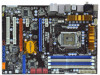
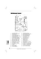
Motherboard Layout English 1 PS2_USB_PWR1 Jumper 2 ATX 12V Power Connector (ATX12V1) 3 1156-Pin CPU Socket 4 2 x 240-pin DDR3 DIMM Slots (Dual Channel: DDR3_A2, DDR3_B2, Blue) 5 2 x 240-pin DDR3 DIMM Slots (Dual Channel: DDR3_A1, DDR3_B1, White) 6 ATX Power Connector (ATXPWR1) 7 Chassis Fan Connector (CHA_FAN1) 8 Chassis Fan Connector (CHA_FAN2) 9 SATAII Connector (SATAII_1_2, Red) 10 SATAII Connector (SATAII_3_4, Red) 11 SATAII Connector (SATAII_5_6, Red) 12 Chassis Fan Connector (CHA_FAN3) 13 Intel P55 Chipset 14 Primary IDE Connector (IDE1, Blue) 15 Clear CMOS Jumper (CLRCMOS1) 16 16Mb SPI Flash 17 Dr. Debug 18 Reset Switch (RSTBTN) 19 TPM Header (TPM1) 20 Power Switch (PWRBTN) 21 Infrared Module Header (IR1) 22 System Panel Header (PANEL1, Orange) 23 USB 2.0 Header (USB12_13, Blue) 24 USB 2.0 Header (USB10_11, Blue) 25 USB 2.0 Header (USB8_9, Blue) 26 Front Panel IEEE 1394 Header (FRONT_1394, Red) 27 Floppy Connector (FLOPPY1) 28 COM Port Header (COM1) 29 HDMI_SPDIF Header (HDMI_SPDIF1, Yellow) 30 Front Panel Audio Header (HD_AUDIO1, Lime) 31 Internal Audio Connector: CD1 (Black) 32 PCI Slots (PCI1-2) 33 PCI Express 2.0 x16 Slot (PCIE4, Orange) 34 PCI Express 2.0 x1 Slot (PCIE3, White) 35 PCI Express 2.0 x16 Slot (PCIE2, Blue) 36 PCI Express 2.0 x1 Slot (PCIE1, White) 37 CPU Fan Connector (CPU_FAN1) 38 Power Fan Connector (PWR_FAN1) 2 ASRock P55 Pro Motherboard
-
 1
1 -
 2
2 -
 3
3 -
 4
4 -
 5
5 -
 6
6 -
 7
7 -
 8
8 -
9
-
10
-
11
-
12
-
13
-
14
-
15
-
16
-
17
-
18
-
19
-
20
-
21
-
22
-
23
-
24
-
25
-
26
-
27
-
28
-
29
-
30
-
31
-
32
-
33
-
34
-
35
-
36
-
37
-
38
-
39
-
40
-
41
-
42
-
43
-
44
-
45
-
46
-
47
-
48
-
49
-
50
-
51
-
52
-
53
-
54
-
55
-
56
-
57
-
58
-
59
-
60
-
61
-
62
-
63
-
64
-
65
-
66
-
67
-
68
-
69
-
70
-
71
-
72
-
73
-
74
-
75
-
76
-
77
-
78
-
79
-
80
-
81
-
82
-
83
-
84
-
85
-
86
-
87
-
88
-
89
-
90
-
91
-
92
-
93
-
94
-
95
-
96
-
97
-
98
-
99
-
100
-
101
-
102
-
103
-
104
-
105
-
106
-
107
-
108
-
109
-
110
-
111
-
112
-
113
-
114
-
115
-
116
-
117
-
118
-
119
-
120
-
121
-
122
-
123
-
124
-
125
-
126
-
127
-
128
-
129
-
130
-
131
-
132
-
133
-
134
-
135
-
136
-
137
-
138
-
139
-
140
-
141
-
142
-
143
-
144
-
145
-
146
-
147
-
148
-
149
-
150
-
151
-
152
-
153
-
154
-
155
-
156
-
157
-
158
-
159
-
160
-
161
-
162
-
163
-
164
-
165
-
166
-
167
-
168
-
169
-
170
-
171
-
172
-
173
-
174
-
175
-
176
-
177
-
178
-
179
-
180
-
181
-
182
-
183
-
184
-
185
-
186
-
187
-
188
-
189
-
190
-
191
-
192
-
193
-
194
-
195
-
196
-
197
-
198
-
199
-
200
-
201
-
202
-
203
-
204
-
205
-
206
-
207
-
208
-
209
-
210
-
211
-
212
-
213
-
214
-
215
-
216
-
217
-
218
-
219
-
220
-
221
 |
 |
