ASRock P67 Extreme6 Quick Installation Guide
ASRock P67 Extreme6 Manual
 |
View all ASRock P67 Extreme6 manuals
Add to My Manuals
Save this manual to your list of manuals |
ASRock P67 Extreme6 manual content summary:
- ASRock P67 Extreme6 | Quick Installation Guide - Page 1
by ASRock. ASRock assumes no responsibility for any errors or omissions that may appear in this guide. With respect to the contents of this guide, ASRock ASRock Website: http://www.asrock.com Published November 2010 Copyright©2010 ASRock INC. All rights reserved. 1 ASRock P67 Extreme6 Motherboard - ASRock P67 Extreme6 | Quick Installation Guide - Page 2
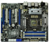
13 14 15 16 17 18 19 20 21 22 23 24 25 26 38 37 36 35 34 33 32 31 30 29 28 27 1 ATX 12V Power Connector (ATX12V1) 25 Power LED Header (PLED1) 2 1155-Pin CPU Socket 26 Chassis Speaker Header 3 CPU Fan Connector (CPU_FAN2) (SPEAKER 1, White) 4 CPU Fan Connector (CPU_FAN1) 27 System Panel - ASRock P67 Extreme6 | Quick Installation Guide - Page 3
SPDIF Out Port 18 Clear CMOS Switch (CLRCBTN) 19 PS/2 Keyboard Port (Purple) * If you want to install USB 3.0 device on this motherboard, we recommend to use 10) (No. 7) (No. 8) (No. 6) 2 V -- -- -- 4 V V -- -- 6 V V V -- 8 V V V V English 3 ASRock P67 Extreme6 Motherboard - ASRock P67 Extreme6 | Quick Installation Guide - Page 4
HDA Primary output" to use Rear Speaker, Central/Bass, and Front Speaker, or select "Realtek HDA Audio 2nd output" to use front panel audio. English 4 ASRock P67 Extreme6 Motherboard - ASRock P67 Extreme6 | Quick Installation Guide - Page 5
ASRock Reminds You... To get better performance in Windows® 7 / 7 64-bit / VistaTM / VistaTM 64bit, it is recommended to set the BIOS option in Storage Configuration to AHCI mode. For the BIOS setup, please refer to the "User Manual" in our support CD for details. 5 ASRock P67 Extreme6 Motherboard - ASRock P67 Extreme6 | Quick Installation Guide - Page 6
DIMM slots - Supports DDR3 2133(OC)/1866(OC)/1600/1333/1066 non-ECC, un-buffered memory (see CAUTION 3) - Max. capacity of system memory: 32GB (see CAUTION 4) - Supports Intel® Extreme Memory Profile (XMP) - 3 x PCI Express 2.0 x16 slots (PCIE2/PCIE4: single at x16 or dual at x8/x8 mode; PCIE5: x4 - ASRock P67 Extreme6 | Quick Installation Guide - Page 7
- 1 x USB 3.0 header (supports 2 USB 3.0 ports) - 1 x Dr. Debug (7-Segment Debug LED) - 1 x Clear CMOS Switch with LED - 1 x Power Switch with LED - 1 x Reset Switch with LED - 64Mb AMI BIOS - AMI UEFI Legal BIOS with GUI support - Supports "Plug and Play" 7 ASRock P67 Extreme6 Motherboard English - ASRock P67 Extreme6 | Quick Installation Guide - Page 8
- ASRock U-COP (see CAUTION 12) - Boot Failure Guard (B.F.G.) - Combo Cooler Option (C.C.O.) (see CAUTION 13) - Good Night LED Hardware - CPU Temperature Sensing Monitor - Chassis Temperature Sensing - CPU/Chassis/Power Fan Tachometer - CPU/Chassis Quiet Fan (Allow Chassis Fan Speed Auto - ASRock P67 Extreme6 | Quick Installation Guide - Page 9
frequency options may depend on the processor. Only K-Series CPU can support DDR3 overclock to 2133 and 1866. 4. Due to the operating system limitation, the actual memory size may be less than 4GB for the reservation for system usage under Windows® 7 / VistaTM / XP. For Windows® OS with 64-bit CPU - ASRock P67 Extreme6 | Quick Installation Guide - Page 10
CPU and the heatsink when you install the PC system. 13. Combo Cooler Option (C.C.O.) provides the flexible option to adopt three different CPU cooler types, Socket LGA 775, LGA 1155 and LGA 1156. Please be noticed that not all the 775 and 1156 CPU Fan can be used. 10 ASRock P67 Extreme6 Motherboard - ASRock P67 Extreme6 | Quick Installation Guide - Page 11
system shall be under 1.00W in off mode condition. To meet EuP standard, an EuP ready motherboard and an EuP ready power supply are required. According to Intel's suggestion, the EuP ready power supply with the power supply manufacturer for more details. 11 ASRock P67 Extreme6 Motherboard English - ASRock P67 Extreme6 | Quick Installation Guide - Page 12
257.21 257.21 257.21 257.21 257.21 257.21 257.21 257.21 257.21 257.21 257.21 * For the latest updates of the supported PCI Express VGA card list for SLITM Mode, please visit our website for details. ASRock website: http://www.asrock.com/support/index.htm English 12 ASRock P67 Extreme6 Motherboard - ASRock P67 Extreme6 | Quick Installation Guide - Page 13
HD 3870 Catalyst 10.9 Catalyst 10.9 Catalyst 10.9 Catalyst 10.9 * For the latest updates of the supported PCI Express VGA card list for CrossFireXTM Mode, please visit our website for details. ASRock website: http://www.asrock.com/support/index.htm English 13 ASRock P67 Extreme6 Motherboard - ASRock P67 Extreme6 | Quick Installation Guide - Page 14
you insert the 1155-Pin CPU into the socket, please check if the CPU surface is unclean or if there is any bent pin on the socket. Do not force to insert the CPU into the socket if above situation is found. Otherwise, the CPU will be seriously damaged. English 14 ASRock P67 Extreme6 Motherboard - ASRock P67 Extreme6 | Quick Installation Guide - Page 15
motherboard for after service. Step 3. Insert the 1155-Pin CPU: Step 3-1. Hold the CPU 1155-Pin CPU alignment key 1155-Pin Socket For proper inserting, please ensure to match the two orientation key notches of the CPU with the two alignment keys of the socket. 15 ASRock P67 Extreme6 Motherboard - ASRock P67 Extreme6 | Quick Installation Guide - Page 16
Please be noticed that this motherboard supports Combo Cooler Option (C.C.O.), which provides the flexible option to adopt three different CPU cooler types, Socket LGA 775, LGA 1155 and LGA 1156. The white throughholes are for Socket LGA 1155/1156 CPU fan. 16 ASRock P67 Extreme6 Motherboard English - ASRock P67 Extreme6 | Quick Installation Guide - Page 17
to install a DDR or DDR2 memory module into DDR3 slot; otherwise, this motherboard and DIMM may be damaged. 5. Some DDR3 1GB double-sided DIMMs with 16 chips may not work on this motherboard. It is not recommended to install them on this motherboard. English 17 ASRock P67 Extreme6 Motherboard - ASRock P67 Extreme6 | Quick Installation Guide - Page 18
permanent damage to the motherboard and the DIMM if you force the DIMM into the slot at incorrect orientation. Step 3. Firmly insert the DIMM into the slot until the retaining clips at both ends fully snap back in place and the DIMM is properly seated. 18 ASRock P67 Extreme6 Motherboard English - ASRock P67 Extreme6 | Quick Installation Guide - Page 19
4. Align the card connector with the slot and press firmly until the card is completely seated on the slot. Step 5. Fasten the card to the chassis with screws. Step 6. Replace the system cover. 19 ASRock P67 Extreme6 Motherboard English - ASRock P67 Extreme6 | Quick Installation Guide - Page 20
that are NVIDIA® certified. 2. Make sure that your graphics card driver supports NVIDIA® SLITM technology. Download the driver from NVIDIA® website (www.nvidia.com). 3. Make sure that your connect the auxiliary power source to the PCI Express graphics cards. 20 ASRock P67 Extreme6 Motherboard English - ASRock P67 Extreme6 | Quick Installation Guide - Page 21
goldfingers on each graphics card. Make sure ASRock SLI_Bridge_2S Card is firmly in place. ASRock SLI_Bridge_2S Card Step4. Connect a VGA cable or a DVI cable to the monitor connector or the DVI connector of the graphics card that is inserted to PCIE2 slot. 21 ASRock P67 Extreme6 Motherboard English - ASRock P67 Extreme6 | Quick Installation Guide - Page 22
, select Set SLI and PhysX configuration. In Set PhysX GPU acceleration item, please select Enabled. In Select an SLI configuration item, please select Enable SLI. And click Apply. C. Reboot your system. D. You can freely enjoy the benefit of SLITM feature. 22 ASRock P67 Extreme6 Motherboard English - ASRock P67 Extreme6 | Quick Installation Guide - Page 23
a registered trademark of NVIDIA® Technologies Inc., and is used only for identification or explanation and to the owners' benefit, without intent to infringe. 23 ASRock P67 Extreme6 Motherboard English - ASRock P67 Extreme6 | Quick Installation Guide - Page 24
the future, please refer to ATITM graphics card manuals for detailed installation guide. Step 1. Insert one Radeon graphics card into PCIE2 slot and the other Radeon graphics card to PCIE4 slot. Make sure that the cards are properly seated on the slots. English 24 ASRock P67 Extreme6 Motherboard - ASRock P67 Extreme6 | Quick Installation Guide - Page 25
provided with the graphics card you purchase, not bundled with this motherboard. Please refer to your graphics card vendor for details.) CrossFire Bridge or Step 3. Connect the DVI monitor cable to the DVI monitor cable to the DVI to D-Sub adapter.) English 25 ASRock P67 Extreme6 Motherboard - ASRock P67 Extreme6 | Quick Installation Guide - Page 26
Bridge to connect Radeon graphics cards on PCIE4 and PCIE5 slots. (CrossFireTM Bridge is provided with the graphics card you purchase, not bundled with this motherboard. Please refer to your graphics card vendor for details.) 26 ASRock P67 Extreme6 Motherboard - ASRock P67 Extreme6 | Quick Installation Guide - Page 27
D-Sub adapter to convert the DVI connector to D-Sub interface, and then connect the D-Sub monitor cable to the DVI to D-Sub adapter.) English 27 ASRock P67 Extreme6 Motherboard - ASRock P67 Extreme6 | Quick Installation Guide - Page 28
Control Center". Click "View", select "CrossFireXTM", and then check the item "Enable CrossFireXTM". Select "2 GPUs" and click "Apply" (if you install two Radeon graphics cards). Select "3 GPUs" and click "OK" (if you install three Radeon graphics cards). English 28 ASRock P67 Extreme6 Motherboard - ASRock P67 Extreme6 | Quick Installation Guide - Page 29
upgrade. With the external add-on PCI Express VGA cards, you can easily enjoy the benefits of Surround Display feature. For the detailed instruction, please refer to the document at the following path in the Support CD: ..\ Surround Display Information 29 ASRock P67 Extreme6 Motherboard English - ASRock P67 Extreme6 | Quick Installation Guide - Page 30
do not clear the CMOS right after you update the BIOS. If you need to clear the CMOS when you just finish updating the BIOS, you must boot up the system first, and then shut it down before you do the clear-CMOS action. Please be noted that the password, date, time, user default profile, 1394 GUID and - ASRock P67 Extreme6 | Quick Installation Guide - Page 31
SATAII / SATA3 hard disk or the SATAII / SATA3 connector on this motherboard. Please connect the black end of SATA power cable to the power connector on each drive. Then connect the white end of SATA power cable to the power connector of the power supply. English 31 ASRock P67 Extreme6 Motherboard - ASRock P67 Extreme6 | Quick Installation Guide - Page 32
support two USB 2.0 ports. Besides four default USB 3.0 ports on the I/O panel, there is one USB 3.0 header on this motherboard. This USB 3.0 header can support two USB 3.0 ports. This header supports an optional wireless transmitting and receiving infrared module. English 32 ASRock P67 Extreme6 - ASRock P67 Extreme6 | Quick Installation Guide - Page 33
LED): Connect to the power status indicator on the chassis front panel. The LED is on when the system is operating. The LED keeps blinking when the system is in S1 sleep state. The LED is off when the system is in S3/S4 sleep state or powered off (S5). 33 ASRock P67 Extreme6 Motherboard - ASRock P67 Extreme6 | Quick Installation Guide - Page 34
No. 9) CPU Fan Connectors (4-pin CPU_FAN1) 1 2 (see p.2 No. 4) 3 4 GND +12V CHA_FAN_SPEED GND +12V PWR_FAN_SPEED GND +12V CPU_FAN_SPEED FAN_SPEED_CONTROL Please connect the CPU fan cable to the connector and match the black wire to the ground pin. English 34 ASRock P67 Extreme6 Motherboard - ASRock P67 Extreme6 | Quick Installation Guide - Page 35
) support, the 3-Pin CPU fan still can work successfully even without the fan speed control function. If you plan to connect the 3-Pin CPU fan to the CPU fan connector on this motherboard, please connect it to Pin 1-3. Pin 1-3 Connected (3-pin CPU_FAN2) (see p.2 No. 3) 3-Pin Fan Installation ATX - ASRock P67 Extreme6 | Quick Installation Guide - Page 36
, there is one IEEE 1394 header (FRONT_1394) on this motherboard. This IEEE 1394 header can support one IEEE 1394 port. This COM1 header supports a serial port module. HDMI_SPDIF Header (2-pin HDMI_SPDIF1) (see connector of HDMI VGA card to this header. English 36 ASRock P67 Extreme6 Motherboard - ASRock P67 Extreme6 | Quick Installation Guide - Page 37
six chassis screws. Step 5 Plug the Front USB 3.0 cable into the USB 3.0 Step 6 The Front USB 3.0 Panel is ready to use. header (USB3_2_3) on the motherboard. English The Installation Guide of bracket. Step 4 Put the rear USB 3.0 bracket into the chassis. 37 ASRock P67 Extreme6 Motherboard - ASRock P67 Extreme6 | Quick Installation Guide - Page 38
(RSTBTN) (see p.2 No. 23) RESET Reset Switch is a smart switch, allowing users to quickly reset the system. Clear CMOS Switch (CLRCBTN) (see p.3 No. 18) clr CMOS Clear CMOS Switch is a smart switch, allowing users to quickly clear the CMOS values. English 38 ASRock P67 Extreme6 Motherboard - ASRock P67 Extreme6 | Quick Installation Guide - Page 39
. Cache initialization CPU post-memory initialization. Application Processor(s) (AP) initialization CPU post-memory initialization. Boot Strap Processor (BSP) selection CPU post-memory initialization. System Management Mode (SMM) initialization 39 ASRock P67 Extreme6 Motherboard English - ASRock P67 Extreme6 | Quick Installation Guide - Page 40
Recovery firmware image is found Recovery firmware image is loaded Reserved for future AMI progress codes Recovery PPI is not available Recovery capsule is not found Invalid recovery capsule Reserved for future AMI error codes DXE Core is started NVRAM initialization ASRock P67 Extreme6 Motherboard - ASRock P67 Extreme6 | Quick Installation Guide - Page 41
Console input devices connect Super IO Initialization USB initialization is started USB Reset USB Detect USB Enable Reserved for future AMI codes IDE initialization is started IDE Reset IDE Detect IDE Enable SCSI initialization is started SCSI Reset English 41 ASRock P67 Extreme6 Motherboard - ASRock P67 Extreme6 | Quick Installation Guide - Page 42
ROM No Console Output Devices are found No Console Input Devices are found Invalid password Error loading Boot Option (LoadImage returned error) Boot Option is failed (StartImage returned error) Flash update is failed Reset protocol is not available English 42 ASRock P67 Extreme6 Motherboard - ASRock P67 Extreme6 | Quick Installation Guide - Page 43
to install Windows® 7 / 7 64-bit / VistaTM / VistaTM 64-bit / XP / XP 64bit on your SATA / SATAII / SATA3 HDDs with RAID functions, please refer to the document at the following path in the Support CD for detailed procedures: ..\ RAID Installation Guide 43 ASRock P67 Extreme6 Motherboard English - ASRock P67 Extreme6 | Quick Installation Guide - Page 44
Configuration. B. Set the option "SATA Mode" to [IDE]. (For SATA3_0, SATA3_1 and SATA2_2 to SATA2_5 ports.) Set the option "Marvell SATA3 Operation Mode" to [IDE]. (For SATA3_M1 to SATA3_M4 ports.) STEP 2: Install Windows® XP / XP 64-bit OS on your system. 44 ASRock P67 Extreme6 Motherboard English - ASRock P67 Extreme6 | Quick Installation Guide - Page 45
Set the option "SATA Mode" to [AHCI]. (For SATA3_0, SATA3_1 and SATA2_2 to SATA2_5 ports.) Set the option "Marvell SATA3 Operation Mode" to [AHCI]. (For SATA3_M1 to SATA3_M4 ports.) STEP 2: Install Windows® 7 / 7 64-bit / VistaTM / VistaTM 64-bit OS on your system. 45 ASRock P67 Extreme6 Motherboard - ASRock P67 Extreme6 | Quick Installation Guide - Page 46
refer to following steps to set up Teaming function according to the OS you install. For Windows® XP / XP 64-bit OS: 1. Install Teaming driver from the following path of motherboard Support CD: .. \ Drivers \ other \ EXE_Teaming_Green(Normal) (This is a special driver for Teaming function only. If - ASRock P67 Extreme6 | Quick Installation Guide - Page 47
will show below warming message. Please choose Continue Anyway.) 6. After doing above settings, system will auto create a new Local Area Connection. 7. Reboot your system. Then, you will find the Speed column of new Local Area Connection show 2.0Gbps. 47 ASRock P67 Extreme6 Motherboard English - ASRock P67 Extreme6 | Quick Installation Guide - Page 48
driver. 2. After installing driver, please open Teaming Utility in Programs. (Start > Programs > Realtek > Teaming Utility) 3. Click Teaming item and then press Create Team button. 4. Key in Team Name and choose Link Aggregation \ LACP (802.3ad) for Settings. 48 ASRock P67 Extreme6 Motherboard - ASRock P67 Extreme6 | Quick Installation Guide - Page 49
will show below warming message. Please choose Continue Anyway.) 6. After doing above settings, system will auto create a new Local Area Connection. 7. Reboot your system. Then, you will find the Speed column of new Local Area Connection show 2.0Gbps. 49 ASRock P67 Extreme6 Motherboard English - ASRock P67 Extreme6 | Quick Installation Guide - Page 50
detailed information about BIOS Setup, please refer to the User Manual (PDF file) contained in the Support CD. 4. Software Support CD information This motherboard supports various Microsoft® Windows® operating systems: 7 / 7 64-bit / VistaTM / VistaTM 64-bit / XP / XP 64-bit. The Support CD that came - ASRock P67 Extreme6 | Quick Installation Guide - Page 51
1.1 Kartoninhalt ASRock P67 Extreme6 Motherboard (ATX-Formfaktor: 30.5 cm x 24.4 cm; 12.0 Zoll x 9.6 Zoll) ASRock P67 Extreme6 Schnellinstallationsanleitung ASRock P67 Extreme6 Support-CD Ein Flachbandkabel für ein 3,5-Zoll-Diskettenlaufwerk Sechs Serial ATA (SATA) -Datenkabel (optional) Zwei Serial - ASRock P67 Extreme6 | Quick Installation Guide - Page 52
LAN 10/100/1000 Mb/s - Realtek RTL8111E - Unterstützt Wake-On-LAN - Unterstützt LAN-Kabelerkennung - Unterstützt energieeffizientes Ethernet 802.3az - Unterstützt duales LAN mit Teamfunktion I/O Panel - 1 x PS/2-Mausanschluss - 1 x PS/2-Tastaturanschluss ASRock P67 Extreme6 Motherboard Deutsch - ASRock P67 Extreme6 | Quick Installation Guide - Page 53
- 1 x HDMI_SPDIF-Anschluss - 1 x IEEE 1394-Anschluss - 1 x Betriebs-LED-Header - CPU/Gehäuse/Stromlüfter-Anschluss - 24-pin ATX-Netz-Header - 8-pin anschluss für 12V-ATX-Netzteil - SLI/XFIRE-Netz-Header - Anschluss für Audio auf der Gehäusevorderseite 53 ASRock P67 Extreme6 Motherboard Deutsch - ASRock P67 Extreme6 | Quick Installation Guide - Page 54
durch CPU- oder MB-Temperatur) - Mehrstufige Geschwindigkeitsteuerung für CPU-/ Gehäuselüfter - Spannungsüberwachung: +12V, +5V, +3.3V, Vcore Betriebssysteme - Unterstützt Microsoft® Windows® 7 / 7 64-Bit / VistaTM / VistaTM 64-Bit / XP / XP 64-Bit 54 ASRock P67 Extreme6 Motherboard - ASRock P67 Extreme6 | Quick Installation Guide - Page 55
zeigt Ihnen zur Anpassung Lüftergeschwindigkeit und Temperatur an. Bei der Übertaktung können Sie die CPU-Frequenz zur Erzielung optimaler Systemleistung übertakten. OC DNA ermöglicht Ihnen die Speicherung Ihrer OC-Einstellungen als Profil, welches Sie 55 ASRock P67 Extreme6 Motherboard Deutsch - ASRock P67 Extreme6 | Quick Installation Guide - Page 56
bis zu 40 % schneller als zuvor. Der ASRock APP Charger ermöglicht Ihnen die schnelle Aufladung mehrerer Apple-Geräte gleichzeitig; der Ladevorgang wird sogar dann fortgesetzt, wenn der PC den Ruhezustand (S1), Suspend to RAM-Modus (S3) oder Tiefschlafmo 56 ASRock P67 Extreme6 Motherboard Deutsch - ASRock P67 Extreme6 | Quick Installation Guide - Page 57
Sie mit den Windows®-Betriebssystemen 7 / 7, 64 Bit / VistaTM / VistaTM 64 Bit und dem Internet Explorer ab Version 8 nutzen. ASRock-Website: http:// www.asrock.com/Feature/SmartView/index.asp 11. Obwohl dieses Motherboard stufenlose Steuerung bietet, wird Overclocking nicht empfohlen. Frequenzen - ASRock P67 Extreme6 | Quick Installation Guide - Page 58
) Socket Body 1155-Pin Sockel Übersicht Bevor Sie die 1155-Pin CPU in den Sockel sitzen, prüfen Sie bitte, ob die CPU-Oberfläche sauber ist und keine der Kontakte verbogen sind. Setzen Sie die CPU nicht mit Gewalt in den Sockel, dies kann die CPU schwer beschädigen. Deutsch 58 ASRock P67 Extreme6 - ASRock P67 Extreme6 | Quick Installation Guide - Page 59
dem IHS (Integrated Heat Sink - integrierter Kühlkörper) nach oben. Suchen Sie Pin 1 und die zwei Orientierungseinkerbungen. Orientierungskerbe Ausrichtungsmarkierung Pin1 Orientierungskerbe 1155-Pin CPU Ausrichtungsmarkierung 1155-Pin Sockel Pin1 59 ASRock P67 Extreme6 Motherboard Deutsch - ASRock P67 Extreme6 | Quick Installation Guide - Page 60
. Schritt 3-3. Drücken Sie die CPU vorsichtig in vertikaler Richtung in den Sockel. Schritt 3-4. Prüfen Sie, dass die CPU ordnungsgemäß im Sockel sitzt und die Ladehebel. Schritt 4-3. Sichern Sie Ladehebel und Ladeplatte mithilfe des Hebelverschlusses. 60 ASRock P67 Extreme6 Motherboard Deutsch - ASRock P67 Extreme6 | Quick Installation Guide - Page 61
dieses Motherboard die Combo-Kühleroption unterstützt, die eine flexible Möglichkeit zur Aufnahme von drei verschiedenen CPU-Kühlertypen, Socket LGA 775, LGA 1155 und LGA 1156, bietet. Das weiße Durchgangsloch ist für den CPU-Lüfter im Socket LGA 1155/1156 vorgesehen. Deutsch 61 ASRock P67 Extreme6 - ASRock P67 Extreme6 | Quick Installation Guide - Page 62
zu installieren; andernfalls könnten Motherboard und DIMMs beschädigt werden. 5. Einige doppelseitige 1 GB-DDR3-DIMMs mit 16 Chips funktionieren möglicherweise nicht auf diesem Motherboard. Wir empfehlen, sie nicht auf diesem Motherboard zu installieren. 62 ASRock P67 Extreme6 Motherboard Deutsch - ASRock P67 Extreme6 | Quick Installation Guide - Page 63
die Steckplätze, so dass die Halteklammern an beiden Enden des Moduls einschnappen und das DIMM-Modul fest an Ort und Stelle sitzt. Deutsch 63 ASRock P67 Extreme6 Motherboard - ASRock P67 Extreme6 | Quick Installation Guide - Page 64
und PCIE4-Steckplätzen. Daher funktionieren diese zwei Steckplätze mit x8-Bandbreite. 3. Im 3-Way CrossFireXTM-Modus installieren Sie PCI Express x16Grafikkarten in den PCIE2-, PCIE4- und PCIE5-Steckplä die Karte vor, ehe Sie mit der Installation beginnen. 64 ASRock P67 Extreme6 Motherboard Deutsch - ASRock P67 Extreme6 | Quick Installation Guide - Page 65
Windows® XP mit Service PCI Express-VGA-Karte können Sie die Vorteile der Surround Display-Funktion problemlos genießen. Für detaillierte Informationen, siehe folgendes Dokument auf beiliegender Support-CD: ..\ Surround Display Information Deutsch 65 ASRock P67 Extreme6 Motherboard - ASRock P67 Extreme6 | Quick Installation Guide - Page 66
herunter. Bitte beachten Sie, dass Kennwort, Datum, Uhrzeit, benutzerdefiniertes Profil, 1394 GUID und MAC-Adresse nur gelöscht werden, wenn die CMOS-Batterie entfernt wird. Der CMOS löschen-Schalter hat dieselbe Funktion wie der CMOS löschen-Jumper. Deutsch 66 ASRock P67 Extreme6 Motherboard - ASRock P67 Extreme6 | Quick Installation Guide - Page 67
20) (SATA3_M4: siehe S.2 - No. 19) Diese sechs Serial ATA3(SATA3-)Verbínder Option) SJedes Ende des SATA Datenkabels kann an die SATA / SATAII / SATA3 Festplatte oder das SATAII / SATA3 Verbindungsstück auf dieser Hauptplatine angeschlossen werden. Deutsch 67 ASRock P67 Extreme6 Motherboard - ASRock P67 Extreme6 | Quick Installation Guide - Page 68
0Anschlussleisten am Motherboard. Pro USB 2.0Anschlussleiste werden zwei USB 2.0-Ports unterstützt. Neben vier Standard-USB 3.0-Ports am E/A-Panel befindet sich ein USB 3.0Header an diesem Motherboard. Dieser USB 3.0Header kann zwei USB 3.0Ports unterstützen. ASRock P67 Extreme6 Motherboard Deutsch - ASRock P67 Extreme6 | Quick Installation Guide - Page 69
werden. E. So aktivieren Sie das Mikrofon an der Vorderseite. Bei den Betriebssystemen Windows® XP / XP 64 Bit: Wählen Sie „Mixer". Wählen Sie „Recorder" (Rekorder). Klicken Sie No. 27) Dieser Header unterstützt mehrere Funktion der Systemvorderseite. Deutsch 69 ASRock P67 Extreme6 Motherboard - ASRock P67 Extreme6 | Quick Installation Guide - Page 70
leuchtet, wenn das System in Betrieb ist. Die LED blinkt im S1-Zustand. Im S3-/S4- oder S5-Zustand (ausgeschaltet) leuchtet die LED nicht. 70 ASRock P67 Extreme6 Motherboard - ASRock P67 Extreme6 | Quick Installation Guide - Page 71
Motherboard einen vierpoligen CPU-Lüfteranschluss (Quiet Fan) bietet, können auch CPU-Lüfter ATX-Netzteil verwendet werden. Um ein 20-pol. ATX-Netzteil zu verwenden, stecken Sie den Stecker mit Pin 1 und Pin 13 ein. Installation eines 20-pol. ATX-Netzteils 1 ASRock P67 Extreme6 Motherboard - ASRock P67 Extreme6 | Quick Installation Guide - Page 72
Ihre Energieversorgung zusammen mit dem Pin 1 und Pin 5 ein. 8 5 Installation der 4-Pin ATX 12V Energieversorgung 4 1 SLI/XFIRE-Stromanschluss (4-pin SLI/XFIRE_POWER1) (siehe S.2 - No. 48 wird verwendet, um ein COM-Anschlussmodul zu unterstützen. Deutsch 72 ASRock P67 Extreme6 Motherboard - ASRock P67 Extreme6 | Quick Installation Guide - Page 73
4 Montieren Sie die USB 3.0-Frontblende mit sechs Gehäuseschrauben am Festplatteneinschub. Schritt 5 Schließen Sie das Kabel der USB 3.0-Frontblende am USB 3.0-Header (USB3_2_3) am Motherboard an. Schritt 6 Die USB 3.0-Frontblende ist nun einsatzbereit. Deutsch 73 ASRock P67 Extreme6 Motherboard - ASRock P67 Extreme6 | Quick Installation Guide - Page 74
) ist ein Schnellschalter, mit dem Benutzer das System schnell zurücksetzen können. CMOS löschen-Schalter (CLRCBTN) (siehe S.3 - No. 18) clr CMOS Der CMOS löschen-Schalter ist ein Schnellschalter, mit dem Benutzer die CMOS-Werte schnell löschen können. 74 ASRock P67 Extreme6 Motherboard Deutsch - ASRock P67 Extreme6 | Quick Installation Guide - Page 75
, gehen Sie bitte wie folgt vor. Verwendung von SATA / SATAII / SATA3-Festplatten ohne NCQ-Funktionen SCHRITT 1: UEFI einrichten. A. Rufen Sie das UEFI SETUP UTILITY auf, wählen Sie den „Advanced"- Bildschirm (Erweitert), dann „Storage Configuration". 75 ASRock P67 Extreme6 Motherboard Deutsch - ASRock P67 Extreme6 | Quick Installation Guide - Page 76
Sie "SATA Mode" auf [AHCI]. (Für SATA3_0, SATA3_1 und SATA2_2 zu SATA2_5.) Stellen Sie "Marvell SATA3 Operation Mode" auf [AHCI]. (Für SATA3_M1 zu SATA3_M4.) SCHRITT 2: Installieren Sie Windows® 7 / 7 64-Bit / VistaTM / VistaTM 64-Bit in Ihrem System. 76 ASRock P67 Extreme6 Motherboard Deutsch - ASRock P67 Extreme6 | Quick Installation Guide - Page 77
der Support-CD, um die Menüs aufzurufen. Das Setup-Programm soll es Ihnen so leicht wie möglich machen. Es ist menügesteuert, d.h. Sie können in den verschiedenen Untermenüs Ihre Auswahl treffen und die Programme werden dann automatisch installiert. 77 ASRock P67 Extreme6 Motherboard Deutsch - ASRock P67 Extreme6 | Quick Installation Guide - Page 78
sous Windows® 7 / 7 64 bits / VistaTM / VistaTM 64 bits, il est recommandé de paramétrer l'option BIOS dans Configuration de stockage en mode AHCI. Pour plus de détails sur l'installation BIOS, référez-vous au "Mode d'emploi" sur votre CD de support. 78 ASRock P67 Extreme6 Motherboard Fran - ASRock P67 Extreme6 | Quick Installation Guide - Page 79
Mb/s - Realtek RTL8111E - Support du Wake-On-LAN - Prise en charge de la détection de câble LAN - Prend en charge la norme Energy Efficient Ethernet (Ethernet à efficacité énergétique) 802.3az - Prend en charge le Dual LAN avec la fonction Teaming (pairage) 79 ASRock P67 Extreme6 Motherboard Français - ASRock P67 Extreme6 | Quick Installation Guide - Page 80
charge un taux de transfert de données pouvant aller jusqu'à 3.0Go/s, supporte RAID (RAID 0, RAID 1, RAID 10, RAID 5 et Intel Rapid Storage), NCQ, AHCI et « Hot Plug » Connecteur HDMI_SPDIF - 1 x Connecteur IEEE 1394 - 1 x Connecteur de LED d'alimentation Français 80 ASRock P67 Extreme6 Motherboard - ASRock P67 Extreme6 | Quick Installation Guide - Page 81
voir ATTENTION 12) - Garde d'échec au démarrage (B.F.G.) - Combo Cooler Option (C.C.O.) (voir ATTENTION 13) - DEL veilleuse - Contrôle de la température CPU - Mesure de température de la carte mère - Tachéomètre ventilateur processeur/châssis/ventilateur Français 81 ASRock P67 Extreme6 Motherboard - ASRock P67 Extreme6 | Quick Installation Guide - Page 82
écisément différentes fonctions du système, via une interface facile à utiliser, incluant Moniteur de périphériques, Contrôle du ventilateur, Overclocking, OC DNA et IES. Dans Moniteur de périphériques, il affiche les valeurs principales de votre système. 82 ASRock P67 Extreme6 Motherboard Français - ASRock P67 Extreme6 | Quick Installation Guide - Page 83
, que vous pouvez ajuster. Dans Overclocking, vous pouvez overclocker la fréquence du CPU pour améliorer les performances du syst ASRock, nous fournissons en permanence les derniers jeux compatibles ! Site web ASRock : http://www.asrock.com/Feature/Aiwi/index.asp 83 ASRock P67 Extreme6 Motherboard - ASRock P67 Extreme6 | Quick Installation Guide - Page 84
CPU le dissipateur lors de l'installation du PC. 13. Le Combo Cooler Option (C.C.O.) offre un choix flexible pour adopter trois types différents de refroidisseur sde CPU, les sockets LGA 775, LGA 1155 votre fournisseur de courant pour plus de détails. 84 ASRock P67 Extreme6 Motherboard Français - ASRock P67 Extreme6 | Quick Installation Guide - Page 85
support socket, veuillez vérifier que la surface du processeur est bien propre, et qu'il n'y a aucune broche tordue sur le socket. Si c'est le cas, ne forcez pas pour insérer le processeur dans le socket. Sinon, le processeur sera gravement endommagé. Français 85 ASRock P67 Extreme6 Motherboard - ASRock P67 Extreme6 | Quick Installation Guide - Page 86
tre mis en place si vous renvoyez la carte mère pour service après vente. Etape 3. Insérez le processeur 1155 broches : Etape 3-1. Tenez le processeur par ses bords là broche 1 broche 1 Encoche d'orientation Détrompeur Socket 1155 broches Processeur 1155 broches 86 ASRock P67 Extreme6 Motherboard - ASRock P67 Extreme6 | Quick Installation Guide - Page 87
l'installation du dissipateur thermique pour un processeur 1155 broches. Etape 1. Appliquez le matériau d'interface thermique au centre de IHS sur la surface du socket. (Appliquez le matériau d'interface thermique) Apply Thermal Interface Material Français 87 ASRock P67 Extreme6 Motherboard - ASRock P67 Extreme6 | Quick Installation Guide - Page 88
option Combo Cooler Option (C.C.O.), qui offre un choix flexible pour adopter trois types différents de refroidisseurs de CPU, les sockets LGA 775, LGA 1155 et LGA 1156. Les trous traversant blancs sont pour le ventilateur de CPU au socket LGA 1155/1156. Français 88 ASRock P67 Extreme6 Motherboard - ASRock P67 Extreme6 | Quick Installation Guide - Page 89
des modules m émoire [DIMM] La carte mère P67 Extreme6 dispose de quatre emplacements DIMM DDR3 (Double Data Rate 3) de 240-broches, et supporte la Technologie de Mémoire à Canal Double. Pour effectuer carte mère et les DIMM pourraient être endommagés. Français 89 ASRock P67 Extreme6 Motherboard - ASRock P67 Extreme6 | Quick Installation Guide - Page 90
jusqu'à ce que les clips de maintien situés aux deux extrémités se ferment complètement et que le module DIMM soit inséré correctement. 90 ASRock P67 Extreme6 Motherboard - ASRock P67 Extreme6 | Quick Installation Guide - Page 91
Par conséquent, ces deux fentes fonctionneront avec une largeur de bande x8. 3. En mode CrossFireXTM trois voies, installez les cartes graphiques PCI Express x16 dans les fentes PCIE2, PCIE4 et PCIE5. Par cons 4. Fixez la carte sur le châssis à l'aide d'une vis. 91 ASRock P67 Extreme6 Motherboard - ASRock P67 Extreme6 | Quick Installation Guide - Page 92
PCI Express, vous pouvez facilement jouir des avantages de la caractéristique de l'affichage Surround. Pour les instructions détaillées, veuillez vous reporter au document qui se trouve sur le chemin suivant dans le CD d'assistance : ..\ Surround Display Information 92 ASRock P67 Extreme6 Motherboard - ASRock P67 Extreme6 | Quick Installation Guide - Page 93
que le mot de passe, la date, l'heure, le profil par défaut de l'utilisateur, 1394 GUID et l'adresse MAC seront effacés seulement si la batterie du CMOS est enlevée. Le commutateur Effacer CMOS présente la même fonction que le cavalier Effacer CMOS. Français 93 ASRock P67 Extreme6 Motherboard - ASRock P67 Extreme6 | Quick Installation Guide - Page 94
p.2 No. 20) (SATA3_M4: voir p.2 No. 19) SATA2_3 SATA2_5 SATA2_2 SATA2_4 Ces quatre connecteurs Série option) Toute cote du cable de data SATA peut etre connecte au disque dur SATA / SATAII / SATA3 ou au connecteur SATAII / SATA3 sur la carte mere. Français 94 ASRock P67 Extreme6 Motherboard - ASRock P67 Extreme6 | Quick Installation Guide - Page 95
ATA (SATA) (en option) connecter au connecteur d'alimentation En-tête USB 3.0 (USB3_2_3 br.19) (voir p.2 No. 35) USB_PWR P-9 P+9 GND DUMMY 1 GND P+8 P-8 USB_PWR USB_PWR P-11 P+11 GND DUMMY 1 GND P+10 P-10 USB_PWR USB_PWR P-13 P+13 GND DUMMY + ID 95 ASRock P67 Extreme6 Motherboard Français - ASRock P67 Extreme6 | Quick Installation Guide - Page 96
J_SENSE OUT2_R MIC2_R MIC2_L Cet en-tête supporte un module infrarouge optionnel de transfert et pour fonctionner correctement. Veuillez suivre les instructions dans notre manuel et le manuel de ch d'exploitation Windows® 7 / 7 64 bits / VistaTM / VistaTM 64 bits : ASRock P67 Extreme6 Motherboard - ASRock P67 Extreme6 | Quick Installation Guide - Page 97
br. 4) (voir p.2 No. 28) FAN_SPEED_CONTROL GND +12V CHA_FAN_SPEED Collegare il LED di accensione chassi per indicare lo stato di alimentazione del sistema. Il LED è acceso quando il sistema è in faites correspondre le fil noir à la broche de terre. Français 97 ASRock P67 Extreme6 Motherboard - ASRock P67 Extreme6 | Quick Installation Guide - Page 98
re offre un support de (Ventilateur silencieux ventilateur de CPU à 4 broches , le ventilateur de CPU à 3 ATX 1 13 Connecteur ATX 12V (ATX12V1 br.8) (voir p.2 No. 1) 8 5 4 1 Veuillez connecter une unité d'alimentation électrique ATX 12V sur ce connecteur. 98 ASRock P67 Extreme6 Motherboard - ASRock P67 Extreme6 | Quick Installation Guide - Page 99
ATX 12V, il peut toujours travailler si vous adoptez une approche traditionnelle à 4 broches ATX 12V alimentation. Pour utiliser l'alimentation des 4 broches ATX sur cette carte mere. Le header de IEEE 1394 peut supporter un port de IEEE 1394. Cette en-tête de port ASRock P67 Extreme6 Motherboard - ASRock P67 Extreme6 | Quick Installation Guide - Page 100
peut maintenant être utilisé. Français Le Guide d'installation du Support arrière USB 3.0 Étape 1 Dévissez les support arrière USB 3.0. Étape 3 Vissez les deux vis dans le support arrière USB 3.0. Étape 4 Placez le support arrière USB 3.0 dans le châssis. 100 ASRock P67 Extreme6 Motherboard - ASRock P67 Extreme6 | Quick Installation Guide - Page 101
de réinitialisation est un interrupteur rapide, qui permet à l'utilisateur de réinitialiser rapidement le système. L'interrupteur d'effacement de CMOS est un interrupteur rapide qui permet à l'utilisateur d'effacer rapidement les valeurs du CMOS. Français 101 ASRock P67 Extreme6 Motherboard - ASRock P67 Extreme6 | Quick Installation Guide - Page 102
à UEFI SETUP UTILITY (Utilitaire de configuration UEFI) → écran Avancé → Configuration Storage. B. Réglez «SATA Mode « sur [IDE]. (Pour SATA3_0, SATA3_1 et SATA2_2 à SATA2_5.) Réglez «Marvell SATA3 Operation Mode « sur [IDE]. (Pour SATA3_M1 à SATA3_M4.) 102 ASRock P67 Extreme6 Motherboard Français - ASRock P67 Extreme6 | Quick Installation Guide - Page 103
« sur [AHCI]. (Pour SATA3_0, SATA3_1 et SATA2_2 à SATA2_5.) Réglez «Marvell SATA3 Operation Mode « sur [AHCI]. (Pour SATA3_M1 à SATA3_M4.) ETAPE 2: Installer le système d'exploitation Windows® 7 / 7 64-bit / VistaTM / VistaTM 64-bit sur votre système. 103 ASRock P67 Extreme6 Motherboard Français - ASRock P67 Extreme6 | Quick Installation Guide - Page 104
BIOS, veuillez consulter le Guide de l'utilisateur (fichier PDF) dans le CD technique. 4. Informations sur le CD de support Cette carte mère supporte divers systèmes d'exploitation Microsoft® Windows®: 7 / 7 64 bits / VistaTM / VistaTM 64 bits / XP / XP 64 104 ASRock P67 Extreme6 Motherboard Français - ASRock P67 Extreme6 | Quick Installation Guide - Page 105
7 64-bit / VistaTM / VistaTM 64-bit, si consiglia di impostare l'opzione BIOS in Storage Configuration (Configurazione di archiviazione) sulla modalità AHCI. Per l'impostazione BIOS, fare riferimento a "User Manual" (Manuale dell'utente) nel CD di supporto per dettagli. ASRock P67 Extreme6 Motherboard - ASRock P67 Extreme6 | Quick Installation Guide - Page 106
OC)/1866(OC)/1600/1333/1066 non-ECC, momoria senza buffer (vedi ATTENZIONE 3) - Capacità massima della memoria di sistema: 32GB (vedi ATTENZIONE 4) - Supporto di Intel® XMP (Extreme Memory Profile) - 3 x Alloggi PCI Express 2.0 x16 (PCIE2/PCIE4: singolo a modalità x16 o doppio a modalità x8/x8; PCIE5 - ASRock P67 Extreme6 | Quick Installation Guide - Page 107
- 8-pin connettore ATX 12V - Collettore alimentazione SLI/XFIRE - Connettore audio sul pannello frontale - 4 x Collettore USB 2.0 (supporta 8 porte USB 2.0) - 1 x Collettore USB 3.0 (supporta 2 porte USB 3.0) - 1 x Dr. Debug (LED debug con 7 segmenti) Italiano 107 ASRock P67 Extreme6 Motherboard - ASRock P67 Extreme6 | Quick Installation Guide - Page 108
CPU/chassis con controllo di varie velocità - Voltaggio: +12V, +5V, +3.3V, Vcore - Microsoft® Windows® 7 / 7 64 bit / VistaTM / VistaTM 64 bit / XP / XP 64 bit - FCC, CE, WHQL - Predisposto ErP/EuP (è necessaria l'alimentazione predisposta per il sistema ErP/EuP) (vedi ATTENZIONE 14) ASRock P67 - ASRock P67 Extreme6 | Quick Installation Guide - Page 109
migliorare l'efficienza quando i core CPU sono inattivi senza sacrificare le prestazioni di computazione. Vistare il nostro per informazioni sulle procedure operative dell'utilità AXTU (ASRock Extreme Tuning Utility). Sito ASRock: http://www.asrock.com ASRock P67 Extreme6 Motherboard 109 Italiano - ASRock P67 Extreme6 | Quick Installation Guide - Page 110
amici. Per utilizzare la funzione SmartView, assicurarsi che la versione del sistema operativo sia Windows® 7 / 7 64 bit / VistaTM / VistaTM 64 bit e che la versione del browser sia IE8. Sito web ASRock: http://www.asrock.com/Feature/SmartView/index.asp 110 ASRock P67 Extreme6 Motherboard Italiano - ASRock P67 Extreme6 | Quick Installation Guide - Page 111
(Combo Cooler Option) fornisce la flessibilità di impiegare tre tipi diversi di dispersori di calore CPU, Socket LGA 775, LGA 1155 e LGA 1156. Notare che non possono essere usate tutte le ventole CPU 775 e 1156 ficare ulteriori dettagli con il produttore. 111 ASRock P67 Extreme6 Motherboard Italiano - ASRock P67 Extreme6 | Quick Installation Guide - Page 112
la CPU da 1155-Pin nel socket, verificare che la superficie della CPU sia pulita e che non ci siano pin piegati nel socket. Non forzare l'inserimento della CPU nel socket se ci sono pin piegati. In caso contrario la CPU potrebbe essere seriamente danneggiata. 112 ASRock P67 Extreme6 Motherboard - ASRock P67 Extreme6 | Quick Installation Guide - Page 113
calore integrato) verso l'alto. Individuare il Pin1 ed i due dentelli chiave d'orientamento. Linea nera Dente di orientamento Pin1 Tacca di allineamento Italiano Dente di orientamento CPU da 1155-Pin Pin1 Tacca di allineamento Socket da 1155-Pin 113 ASRock P67 Extreme6 Motherboard - ASRock P67 Extreme6 | Quick Installation Guide - Page 114
denti di allineamento della CPU con le due tacche nel socket. Fase 3-3. Collocare con delicatezza la CPU sulla presa con un movimento puramente verticale. Fase 3-4. Verificare che la CPU sia all'interno della linguetta di ritenzione della leva di carico. 114 ASRock P67 Extreme6 Motherboard Italiano - ASRock P67 Extreme6 | Quick Installation Guide - Page 115
questa scheda mare supporta l'opzione C.C.O. (Combo Cooler Option), che fornisce la flessibilità di impiegare tre tipi diversi di dispersori di calore CPU, Socket LGA 775, LGA 1155 e LGA 1156. I fori di colore bianco sono per la ventola CPU Socket LGA 1155/1156. 115 ASRock P67 Extreme6 Motherboard - ASRock P67 Extreme6 | Quick Installation Guide - Page 116
tre moduli di memoria, è impossibile attivare la tecnologia Dual Channel Memory. 3. Se una coppia di moduli di memoria NON è installata chip potrebbero non funzionare su questa scheda madre. Non se ne raccomanda l'installazione su questa scheda madre. Italiano 116 ASRock P67 Extreme6 Motherboard - ASRock P67 Extreme6 | Quick Installation Guide - Page 117
nello slot fino a far scattare completamente in posizione i fermagli di ritegno alle due estremità e fino ad installare correttamente la DIMM nella sua sede. Italiano 117 ASRock P67 Extreme6 Motherboard - ASRock P67 Extreme6 | Quick Installation Guide - Page 118
PCI Express x16 negli alloggi PCIE2 e PCIE4. Quindi, entrambi gli alloggi lavoreranno a larghezza di banda x8. 3. In modalità 3-Way CrossFireXTM, installare le schede video PCI nello slot. Step 4. Agganciare la scheda allo chassis con le viti. Italiano 118 ASRock P67 Extreme6 Motherboard - ASRock P67 Extreme6 | Quick Installation Guide - Page 119
la scheda integrativa PCI Express VGA, si possono sfruttare con facilità i benefici della funzione Surround Display. Per le istruzioni dettagliate, fare riferimento al documento nel seguente percorso sul CD di supporto: ..\ Surround Display Information 119 ASRock P67 Extreme6 Motherboard Italiano - ASRock P67 Extreme6 | Quick Installation Guide - Page 120
della CMOS. Notare che password, data, ore, profilo utente predefinito, 1394 GUID e indirizzo MAC saranno cancellati solo se è rimossa la batteria della CMOS. L'interruttore Clear CMOS (Cancella CMOS) ha la stessa funzione del jumper Clear CMOS. Italiano 120 ASRock P67 Extreme6 Motherboard - ASRock P67 Extreme6 | Quick Installation Guide - Page 121
: vedi p.2 Nr. 17) (SATA3_M3: vedi p.2 Nr. 20) (SATA3_M4: vedi p.2 Nr. 19) Cavi dati Serial ATA (SATA) (Opzionale) SATA3_M4 SATA3_M2 SATA3_1 SATA3_M3 SATA3_M1 SATA3_0 SATA2_3 SATA2_5 SATA2_2 SATA2_4 di SATAII / SATA3 su questa cartolina base. Italiano 121 ASRock P67 Extreme6 Motherboard - ASRock P67 Extreme6 | Quick Installation Guide - Page 122
vedi p.2 Nr. 30) Collettore USB 3.0 (19-pin USB3_2_3) (vedi p.2 Nr. 35) USB_PWR P-9 P+9 GND DUMMY 1 GND P+8 P-8 USB_PWR USB_PWR P-11 P+11 GND DUMMY 1 GND P+10 P-10 USB_PWR USB_PWR P-13 P+13 GND DUMMY 1 un header USB 3.0 che supporta due porte USB 3.0. Italiano 122 ASRock P67 Extreme6 Motherboard - ASRock P67 Extreme6 | Quick Installation Guide - Page 123
IRRX Questo collettore supporta moduli ad infrarossi optional per la trasmissione e la ricezione senza Attenersi alle istruzioni del nostro manuale e del manuale del telaio per installare il sistema Sistema operativo Windows® 7 / 7 64-bit / VistaTM / VistaTM 64-bit: ASRock P67 Extreme6 Motherboard - ASRock P67 Extreme6 | Quick Installation Guide - Page 124
1 PLEDPLED+ PLED+ Collegare il LED di accensione chassi per indicare lo stato di alimentazione del sistema. Il LED è acceso quando il sistema è in funzione. Il LED continua a lampeggiare in stato S1. Il LED è spento in stato S3/S4 o S5 (spegnimento). Italiano 124 ASRock P67 Extreme6 Motherboard - ASRock P67 Extreme6 | Quick Installation Guide - Page 125
un 12 connettore elettrico ATX a 24 pin, ma può funzionare lo stesso se si adotta un alimentatore ATX a 20 pin. Per usare l'alimentatore ATX a 20 pin, collegare l'alimentatore con il Pin 1 e il Pin 13. Installazione dell'alimentatore ATX a 20 pin 1 ASRock P67 Extreme6 Motherboard 24 13 125 - ASRock P67 Extreme6 | Quick Installation Guide - Page 126
8-pin ATX 12V, l'unita' puo' ancora essere funzionante se viene utilizzata una fornitura elettrica tradizionale a 4-pin ATX 12V. Per usare tale fornitura elettrica 4-pin ATX 12V, LCD . Collegare il connettore HDMI_SPDIF della scheda VGA HDMI a questo header. 126 ASRock P67 Extreme6 Motherboard - ASRock P67 Extreme6 | Quick Installation Guide - Page 127
cavo USB 3.0 e il supporto USB 3.0 posteriore. Punto 3 Avvitare le due viti nel supporto USB 3.0 Punto 4 Inserire il supporto USB 3.0 posteriore. posteriore nel telaio. Italiano 127 ASRock P67 Extreme6 Motherboard - ASRock P67 Extreme6 | Quick Installation Guide - Page 128
il sistema. L'interruttore di reset è un interruttore rapido che consente agli utenti di resettare rapidamente il sistema. L'interruttore di pulizia CMOS è un interruttore rapido che consente agli utenti di cancellare velocemente i valori CMOS. Italiano 128 ASRock P67 Extreme6 Motherboard - ASRock P67 Extreme6 | Quick Installation Guide - Page 129
Configuration. B. Impostare "SATA Mode" su [IDE]. (Per SATA3_0, SATA3_1 e SATA2_2 a SATA2_5.) Impostare "Marvell SATA3 Operation Mode" su [IDE]. (Per SATA3_M1 a SATA3_M4.) Passo 2: Installazione di Windows® XP / XP 64-bit sul sistema. 129 ASRock P67 Extreme6 Motherboard Italiano - ASRock P67 Extreme6 | Quick Installation Guide - Page 130
. B. Impostare "SATA Mode" su [AHCI]. (Per SATA3_0, SATA3_1 e SATA2_2 a SATA2_5.) Impostare "Marvell SATA3 Operation Mode" su [AHCI]. (Per SATA3_M1 a SATA3_M4.) Passo 2: Installazione di Windows® 7 / 7 64-bit / VistaTM / VistaTM 64-bit sul sistema. 130 ASRock P67 Extreme6 Motherboard Italiano - ASRock P67 Extreme6 | Quick Installation Guide - Page 131
sullo chassis del sistema. Per informazioni più dettagliate circa il Setup del BIOS, fare riferimento al Manuale dell'Utente (PDF file) contenuto nel cd di supporto. 4. Software di supporto e informazioni su CD Questa scheda madre supporta vari sistemi operativi Microsoft® Windows®: 7 / 7 64-bit - ASRock P67 Extreme6 | Quick Installation Guide - Page 132
/ VistaTM 64 bits, es recomendable establecer la opción del BIOS de la configuración de almacenamiento en el modo AHCI. Para obtener detalles sobre la configuración del BIOS, consulte el "Manual del usuario" que se encuentra en nuestro CD de soporte. 132 ASRock P67 Extreme6 Motherboard Español - ASRock P67 Extreme6 | Quick Installation Guide - Page 133
(OC)/1866(OC)/1600/1333/1066 non-ECC, memoria de un-buffered (ver ATENCIÓN 3) - Máxima capacidad de la memoria del sistema: 32GB (vea ATENCIÓN 4) - Compatible con Intel® Extreme Memory Profile (XMP) - 3 x ranuras PCI Express 2.0 x16 (PCIE2/PCIE4: sencillas en modo x16 o dobles en modo x8 / x8; PCIE5 - ASRock P67 Extreme6 | Quick Installation Guide - Page 134
1 x cabecera IEEE 1394 - 1 x cabecera de indicador LED de encendido - Conector de ventilador de CPU / chasis / alimentación - 24-pin cabezal de alimentación ATX - 8-pin conector de ATX 12V power - Cabezal de alimentación SLI/XFIRE - Conector de audio de panel frontal ASRock P67 Extreme6 Motherboard - ASRock P67 Extreme6 | Quick Installation Guide - Page 135
y el chasis (ajuste automático de la velocidad del ventilador del chasis en función de la temperatura del procesador o la placa base) - Control de ajuste de la velocidad del ventilador de la CPU y el chasis - Monitor de Voltaje: +12V, +5V, +3.3V, Vcore 135 ASRock P67 Extreme6 Motherboard Español - ASRock P67 Extreme6 | Quick Installation Guide - Page 136
del Manual del 6. ASRock Extreme Tuning control de los ventiladores, muestra la velocidad y la temperatura de los ventiladores y permite ajustarlas. La función de aumento de la velocidad del reloj, permite aumentar la frecuencia de la CPU para conseguir un rendimiento ASRock P67 Extreme6 Motherboard - ASRock P67 Extreme6 | Quick Installation Guide - Page 137
su equipo. ASRock APP Charger le permite cargar de forma rápida muchos dispositivos de Apple simultáneamente e incluso podrá continuar la carga cuando su PC entre en modo de espera (S1), suspendido en RAM (S3), modo de hibernación (S4) o se apague (S5). Una vez ASRock P67 Extreme6 Motherboard 137 - ASRock P67 Extreme6 | Quick Installation Guide - Page 138
Windows® 7 / 7 64 bits / VistaTM / VistaTM 64 bits y que la versión de su explorador es IE8. Sitio Web de ASRock: http://www.asrock.com/Feature/SmartView/index.asp 11. Aunque esta placa base ofrece un control de alimentación para obtener más detalles. 138 ASRock P67 Extreme6 Motherboard Español - ASRock P67 Extreme6 | Quick Installation Guide - Page 139
en el socket, compruebe que la superficie de la CPU se encuentra limpia y no hay ninguna aguja torcida en el socket. No introduzca la CPU en el socket por la fuerza si se produce la situación anterior. Si lo hace, puede producir daños graves en la CPU. Español 139 ASRock P67 Extreme6 Motherboard - ASRock P67 Extreme6 | Quick Installation Guide - Page 140
(Integrated Heat Sink) mirando hacia arriba. Busque la aguja 1 y las dos muescas de orientación. Muesca de orientación Tecla de alineación aguja 1 140 Muesca de orientación CPU de 1155 agujas Tecla de alineación Socket de 1155 agujas ASRock P67 Extreme6 Motherboard aguja 1 - ASRock P67 Extreme6 | Quick Installation Guide - Page 141
un ejemplo para ilustrar la instalación del disipador para la CPU de 1155 agujas. Paso 1. Aplique el material termal de interfaz en el centro del IHS de la superficie del socket. (Aplique el material termal de interfaz) Apply Thermal Interface Material Español 141 ASRock P67 Extreme6 Motherboard - ASRock P67 Extreme6 | Quick Installation Guide - Page 142
una opción flexible que puede adaptarse a tres tipos de disipador de CPU diferentes, correspondientes a los zócalos LGA 775, LGA 1155 y LGA 1156. Los orificios perforados de color blanco están destinados al ventilador de CPU para zócalos LGA 1155/1156. Español 142 ASRock P67 Extreme6 Motherboard - ASRock P67 Extreme6 | Quick Installation Guide - Page 143
2.3 Instalación de Memoria La placa P67 Extreme6 ofrece cuatro ranuras DIMM DDR3 de 240 pines, y soporta Tecnología de Memoria de Doble Canal. Para la configuración en la ranura DDR3; si lo hace, esta placa base y los módulos DIMM pueden resultar dañados. Español 143 ASRock P67 Extreme6 Motherboard - ASRock P67 Extreme6 | Quick Installation Guide - Page 144
5. Algunos módulos de doble cara de 1 GB DDR3 con 16 chips puede que no funcionen en esta placa base. Por tanto, no es recomendable instalarlos en esta de ambos lados queden completamente introducidos en su sitio y la DIMM se haya asentado apropiadamente. 144 ASRock P67 Extreme6 Motherboard Español - ASRock P67 Extreme6 | Quick Installation Guide - Page 145
uti liza con tarjetas PCI Express con ancho de banda x4, o para instalar tarjetas gráficas PCI Express compatibles con la función án con un ancho de banda de x8. 3. En el modo CrossFireXTM de 3 vías, instale tarjetas gráficas PCI Express x16 en las ranuras PCIE2, PCIE4 ASRock P67 Extreme6 Motherboard - ASRock P67 Extreme6 | Quick Installation Guide - Page 146
ón Surround Display . Con la tarjeta PCI Express VGA puede disfrutar fácilmente de la función Surround Display. Para obtener instrucciones detalladas, consulte el documento en la siguiente ruta del CD de soporte: ..\ Surround Display Information 146 ASRock P67 Extreme6 Motherboard Español - ASRock P67 Extreme6 | Quick Installation Guide - Page 147
. Tenga en cuenta que la contraseña, la fecha, la hora, el perfil predeterminado del usuario, el GUID 1394 y la dirección MAC solamente se borrará si la batería CMOS se quita. El conmutador Borrar CMOS tiene la misma función que el puente Borrar CMOS. Español 147 ASRock P67 Extreme6 Motherboard - ASRock P67 Extreme6 | Quick Installation Guide - Page 148
18) (SATA3_M2: vea p.2, N. 17) (SATA3_M3: vea p.2, N. 20) (SATA3_M4: vea p.2, N. 19) Estas seises conexiones de serie ATA3 (SATA3) admiten cables SATA para dispositivos de almacenamiento internos. La interfaz SATAII de SATAII / SATA3 en esta placa base. Español 148 ASRock P67 Extreme6 Motherboard - ASRock P67 Extreme6 | Quick Installation Guide - Page 149
GND DUMMY 1 GND P+8 P-8 USB_PWR USB_PWR P-11 P+11 GND DUMMY 1 GND P+10 P-10 USB_PWR Además de cuatro puertos USB 2.0 predeterminados en el panel de E/S, hay cuatro P+12 P-12 USB_PWR Español Cabezal USB 3.0 (19-pin USB3_2_3) (vea p.2, N. 35) IntA_P2_D+ 3.0. 149 ASRock P67 Extreme6 Motherboard - ASRock P67 Extreme6 | Quick Installation Guide - Page 150
. Por favor, siga las instrucciones en nuestro manual y en el manual de chasis para instalar su sistema. 2. Si Windows® 7 / 7 64-bit / VistaTM / VistaTM 64-bit: Acceda a la ficha "FrontMic" (Micrófono frontal) del panel de control Realtek. Ajuste la posición del control ASRock P67 Extreme6 Motherboard - ASRock P67 Extreme6 | Quick Installation Guide - Page 151
en funcionamiento. El indicador LED parpadeará en el estado S1. El indicador LED se apagará en los estados S3/S4 o S5 (apagado). Español 151 ASRock P67 Extreme6 Motherboard - ASRock P67 Extreme6 | Quick Installation Guide - Page 152
la función de control de velocidad del ventilador ATX de 20 pins tradicional. Para usar una fuente de alimentación ATX de 20 pins, por favor, conecte su fuente de alimentación usando los Pins 1 y 13. Instalación de una Fuente de Alimentación ATX de 20 Pins 1 13 ASRock P67 Extreme6 Motherboard - ASRock P67 Extreme6 | Quick Installation Guide - Page 153
4 1 Tenga en cuenta que es necesario conectar este conector a una toma de corriente con el enchufe ATX 12V, de modo que proporcione suficiente electricidad. De lo contrario no se podrá encender. Aunque esta placa para admitir un módulo de puerto COM. Español 153 ASRock P67 Extreme6 Motherboard - ASRock P67 Extreme6 | Quick Installation Guide - Page 154
Panel frontal USB 3.0 a la cabecera USB 3.0 (USB3_2_3) de la placa base. Paso 6 El Panel frontal USB 3.0 quedará así listo para su uso. Español 154 ASRock P67 Extreme6 Motherboard - ASRock P67 Extreme6 | Quick Installation Guide - Page 155
10 CMOS El conmutador de borrado de memoria CMOS es un conmutador rápido que permite al usuario borrar rápidamente el contenido de la memoria CMOS. El conmutador de encendido es un conmutador rápido que permite al usuario encender / apagar rápidamente el sistema. 155 ASRock P67 Extreme6 Motherboard - ASRock P67 Extreme6 | Quick Installation Guide - Page 156
RAID Si desea instalar Windows® 7 / 7 64 bits / VistaTM / VistaTM 64 bits / XP / XP 64 bits en sus discos duros SATA / SATAII / SATA3 sin funciones RAID, siga los procedimientos que se indican a continuación en función del sistema operativo que tenga instalado. 156 ASRock P67 Extreme6 Motherboard - ASRock P67 Extreme6 | Quick Installation Guide - Page 157
figuración. B. Configure la "SATA Mode" a [AHCI]. (Para SATA3_0, SATA3_1 y SATA2_2 a SATA2_5.) Configure la "Marvell SATA3 Operation Mode" a [AHCI]. (Para SATA3_M1 a SATA3_M4.) PASO 2: Instale Windows® 7 / 7 64 bits / VistaTM / VistaTM 64 bits en su sistema. 157 ASRock P67 Extreme6 Motherboard Español - ASRock P67 Extreme6 | Quick Installation Guide - Page 158
BIOS, por favor refiérase al Manual del Usuario (archivo PDF) contenido en el CD. 4.Información de Software Support CD Esta placa-base soporta diversos tipos de sistema operativo Windows®: 7 / 7 64 bits / VistaTM / VistaTM 64 bits / XP / XP 64 instalación. 158 ASRock P67 Extreme6 Motherboard Español - ASRock P67 Extreme6 | Quick Installation Guide - Page 159
1 ASRock P67 Extreme6 ASRock ASRock BIOS ASRock ASRock. ASRock http://www.asrock.com www.asrock.com/support/index.asp 1.1 ASRock P67 Extreme6 ATX: 12,0 x 9,6 30,5 x 24,4 см) ASRock P67 Extreme6 ASRock P67 Extreme6 1 x 3,5 дюйма 6 x - ASRock P67 Extreme6 | Quick Installation Guide - Page 160
1 Intel® P67 Память Dual Channel DDR3 Memory Technology 2) - 4 x DDR3 DIMM DDR3 2133(OC)/1866(OC)/1600/1333/1066 не- ECC, 3) 32 ГБ 4 Intel® Extreme Memory Profile (XMP) Гнезда - 3 x PCI Express 2.0 x16 (PCIE2/PCIE4 x16, Два - x8/x8; PCIE5: x4) - 2 x PCI Express 2.0 x1 - ASRock P67 Extreme6 | Quick Installation Guide - Page 161
ATX - 8 ATX 12 В SLI/XFIRE - 4 x USB 2.0 8 USB 2.0 - 1 x USB 3.0 2 USB 3.0 - 1 x Dr. Debug (7 - 1 x Clear CMOS - 1 x Power Switch - 1 x Reset Switch - 64Mb AMI BIOS - AMI UEFI Legal BIOS Plug and Play" - ACPI 1.1 ASRock P67 Extreme6 Motherboard - ASRock P67 Extreme6 | Quick Installation Guide - Page 162
CPU/Chassis/Power FAN 12V, +5V, +3.3V, Vcore Microsoft® Windows® 7 / 7 64-bit / VistaTM / 64 VistaTM / XP / XP 64-bit ные - FCC, CE, WHQL ErP/EuP Ready ErP/EuP 14) ты http://www.asrock.com BIOS Untied Overclocking 162 ASRock P67 - ASRock P67 Extreme6 | Quick Installation Guide - Page 163
Hardware Monitor Fan Control Overclocking OC DNA and IES Hardware Monitor Fan Control Overclocking OC DNA IES ASRock Extreme Tuning Utility (AXTU ASRock: http://www.asrock.com 7. ASRock Instant Flash BIOS Flash ROM BIOS MS-DOS или Windows F6 163 ASRock P67 Extreme6 Motherboard - ASRock P67 Extreme6 | Quick Installation Guide - Page 164
S1 S3 S4 S5 APP Charger ASRock: http://www.asrock.com/Feature/AppCharger/index.asp 10. SmartView IE Facebook ASRock SmartView SmartView Windows® 7 / 7 64 bit / VistaTM / VistaTM 64 bit IE8 ASRock: http://www.asrock. com/Feature/SmartView/index.asp 164 ASRock P67 Extreme6 Motherboard - ASRock P67 Extreme6 | Quick Installation Guide - Page 165
11 12 13. Combo Cooler Option (C.C.O Socket LGA775, LGA1155 или LGA1156 LGA775 или LGA1156 14. EuP Energy Using Product EuP 1 EuP Intel EuP 50 5V 100 EuP. 165 ASRock P67 Extreme6 Motherboard - ASRock P67 Extreme6 | Quick Installation Guide - Page 166
2 1 2 3 4 5 2.1 Intel в 1155 Load Plate Load Lever Contact Array Socket Body 1155 1155 Шаг 1 1-1 166 ASRock P67 Extreme6 Motherboard - ASRock P67 Extreme6 | Quick Installation Guide - Page 167
Шаг 1-2. Шаг 1-3. 135 100 Шаг 2 PnP (Pick and Place Cap). 1 PnP 2 Шаг 3 1155 3-1 Шаг 3-2 1 1 1155 1155 1 Шаг 3-3. Шаг 3-4. ASRock P67 Extreme6 Motherboard 167 - ASRock P67 Extreme6 | Quick Installation Guide - Page 168
CPU_FAN1 2 4). Fan cables on side closest to MB header Шаг 3 Fastener slots pointing straight out 4 Шаг 4 Press Down (4 Places) Шаг 5 Шаг 6 168 Combo Cooler Option (C.C.O Socket LGA775, LGA 1155 или LGA1156 Socket LGA1155/1156. ASRock P67 Extreme6 Motherboard - ASRock P67 Extreme6 | Quick Installation Guide - Page 169
(Синий) (Белый) (Синий) (Белый) (1 (2) - (3 3 DDR3 DIMM. 1 DDR3_A1 и DDR3_B1 DDR3_A2 и DDR3_B2). 2 DDR3 DIMM Dual Channel Memory Technology 3 DDR3_A1 и DDR3_A2 Dual Channel Memory Technology 4 DDR, DDR2 DDR3 DIMM 169 ASRock P67 Extreme6 Motherboard - ASRock P67 Extreme6 | Quick Installation Guide - Page 170
5 DIMM 1 DDR3 с 16 DIMM DIMM 1 DIMM 2 DIMM notch break notch break DIMM Шаг 3 DIMM 170 ASRock P67 Extreme6 Motherboard - ASRock P67 Extreme6 | Quick Installation Guide - Page 171
x16 PCIE2. 2 CrossFireXTM или SLITM PCI Express x16 PCIE2 и PCIE4 x8. 3 3-Way CrossFireXTM PCI Express x16 PCIE2, PCIE4 и PCIE5 PCIE2 и PCIE4 x8 PCIE5 - на x4. 4 CHA_FAN1, CHA_FAN2 или CHA_FAN3 5 PCI Express x1 PCIE3 Шаг 1 Шаг 2 171 ASRock P67 Extreme6 Motherboard - ASRock P67 Extreme6 | Quick Installation Guide - Page 172
3D CrossFireXTM Windows® XP с Service Pack 2 / VistaTM / 7 3 CrossFireXTM и Quad CrossFireXTM Windows® VistaTM / 7 AMD ATITM CrossFireXTM 24 2.7 "Surround Display" Surround Display PCI Express VGA Surround Display Surround Display Information 172 ASRock P67 Extreme6 Motherboard - ASRock P67 Extreme6 | Quick Installation Guide - Page 173
2.8 short open 3 1 и 2 CMOS (CLRCMOS1, 3 2, п. 32) CMOS CLRCMOS1 CMOS 15 5 2 и 3 CLRCMOS1 CMOS BIOS CMOS BIOS CMOS 1394 GUID и MAC CMOS. Clear CMOS Clear CMOS. 173 ASRock P67 Extreme6 Motherboard - ASRock P67 Extreme6 | Quick Installation Guide - Page 174
) (SATA3_1 2, п. 15) (SATA3_M1 2, п. 18) (SATA3_M2 2, п. 17) (SATA3_M3 2, п. 20) (SATA3_M4 2, п. 19) Serial ATA3 SATA3 SATA 6,0 SATA3_M4 SATA3_M2 SATA3_1 SATA3_M3 SATA3_M1 SATA3_0 Serial ATA (SATA SATA / SATAII / SATA3 SATAII / SATA3 174 ASRock P67 Extreme6 Motherboard - ASRock P67 Extreme6 | Quick Installation Guide - Page 175
31) (9 USB12_13 2, п. 30) USB 3.0 (19 USB3_2_3 2, п. 35) USB_PWR P-9 P+9 GND DUMMY 1 GND P+8 P-8 USB_PWR USB_PWR P-11 P+11 GND DUMMY 1 GND P+10 P-10 USB_PWR USB_PWR P-13 P+13 GND DUMMY 1 GND 2.0 USB 2.0 USB 2.0. USB 3.0 USB 3.0 USB 3.0 USB 3.0. 175 ASRock P67 Extreme6 Motherboard - ASRock P67 Extreme6 | Quick Installation Guide - Page 176
OUT2_R Audio_L (LIN OUT2_L. C Ground (GND Ground (GND). D MIC_RET и OUT_RET HD AC'97 E Windows® XP / XP 64 Mixer Recorder FrontMic Windows® 7 / 7 64-бита, VistaTM / VistaTM 64 FrontMic Realtek Recording Volume 9 PANEL1 2, п. 27) 176 ASRock P67 Extreme6 Motherboard - ASRock P67 Extreme6 | Quick Installation Guide - Page 177
S4 S5). HDLED 4 SPEAKER1 2, п. 26) Power LED (3 PLED1 2, п. 25) 1 PLEDPLED+ PLED+ Chassis и Power Fan (4 CHA_FAN1) 2, п. 28) (3 CHA_FAN2) FAN_SPEED_CONTROL GND +12V CHA_FAN_SPEED 2, п. 29) Power LED S1 S3/S4 или S5 177 ASRock P67 Extreme6 Motherboard - ASRock P67 Extreme6 | Quick Installation Guide - Page 178
1 GND 2 +12V 3 CPU_FAN_SPEED 4 FAN_SPEED_CONTROL 4 3 3 1-3. 1-3 3 (3 CPU_FAN2 2, п. 3) ATX (24 ATXPWR1 2, п. 7) 12 24 ATX. 1 13 12 24 ивает 24 ATX 20 ATX 20 ATX 1 13. 20 ATX 1 13 178 ASRock P67 Extreme6 Motherboard - ASRock P67 Extreme6 | Quick Installation Guide - Page 179
12V-ATX (8 ATX12V1 2, п. 1) 8 5 4 1 ATX 12 ATX с 8 12V ATX с 4-Pin 12V ATX с 4-Pin 1 5. 8 5 ATX С 4-Pin 12V 4 1 SLI/XFIRE (4 SLI/XFIRE_POWER1 SPDIFOUT HDMI_SPDIF VGA-карту HDMI HDMI HDMI_SPDIF на VGAкарте HDMI. ASRock P67 Extreme6 Motherboard 179 - ASRock P67 Extreme6 | Quick Installation Guide - Page 180
USB 3.0 Шаг 1 USB 3.0 Шаг 2 2,5 USB 3.0 Шаг 3 USB 3.0 2,5 Шаг 4 USB 3.0 Шаг 5 USB 3.0 USB 3.0 (USB3_2_3 Шаг 6 USB 3.0 180 ASRock P67 Extreme6 Motherboard - ASRock P67 Extreme6 | Quick Installation Guide - Page 181
3.0 USB 3.0. Шаг 3 USB 3.0. Шаг 4 USB 3.0 2.10 CMOS CMOS Power Switch (PWRBTN 2, п. 24) Power Switch Reset Switch (RSTBTN 2, п. 23) RESET Reset Switch Clear CMOS Switch (CLRCBTN 3, п. 18) clr CMOS Clear CMOS Switch CMOS. 181 ASRock P67 Extreme6 Motherboard - ASRock P67 Extreme6 | Quick Installation Guide - Page 182
64-bit / XP / XP 64-bit RAID Windows® 7 / 7 64-bit / VistaTM / VistaTM 64-bit / XP / XP 64-bit RAID 2.14.1 Windows® XP / XP 64-bit RAID Windows® XP / XP 64-bit RAID SATA / SATAII / SATA3 NCQ ШАГ 1 UEFI. A UEFI Advanced → Storage Configuration. 182 ASRock P67 Extreme6 Motherboard - ASRock P67 Extreme6 | Quick Installation Guide - Page 183
Windows® XP / XP 64-bit. 2.14.2 Windows® 7 / 7 64-bit / VistaTM / VistaTM 64-bit RAID Windows® 7 / 7 64-bit / VistaTM / VistaTM 64-bit SATA / SATAII / SATA3 RAID AHCI]. (Для SATA3_M1 к SATA3_4.) ШАГ 2 Windows® 7 / 7 64-bit / VistaTM / VistaTM 64-bit. 183 ASRock P67 Extreme6 Motherboard - ASRock P67 Extreme6 | Quick Installation Guide - Page 184
POST Ctrl> + + - ASRock P67 Extreme6 | Quick Installation Guide - Page 185
64-bit / VistaTM / VistaTM 64-bit ile daha iyi performans elde etmek için, Depolama Konfigürasyonundaki BIOS seçeneğini AHCI moduna ayarlamanız tavsiye edilir. BIOS ayarı için, ayrıntıları öğrenmek üzere lütfen destek CD'mizdeki "Kullanıcı Kılavuzu"na bakın. 185 ASRock P67 Extreme6 Motherboard Türk - ASRock P67 Extreme6 | Quick Installation Guide - Page 186
CPU Yonga seti Bellek Genişletme Yuvası Ses LAN Arka Panel G/Ç 186 - ATX Extreme Bellek Profilini (XMP) destekler - 3 x PCI Express 2.0 x16 yuva (PCIE2/PCIE4: tek @ x16 modu veya çift @ x8/x8 modu; PCIE5: x4 modu) - 2 x PCI Express 2.0 x1 yuva - 2 x PCI örü ASRock P67 Extreme6 Motherboard Türkçe - ASRock P67 Extreme6 | Quick Installation Guide - Page 187
USB 3.0 portu destekler) - 1 x Dr. Debug (7 Segmentli Hata Ayıklama LED'i) - 1 x LED'li CMOS'u Temizleme Anahtarı - 1 x LED'li Güç Anahtarı - 1 x LED'li Sıfırlama Anahtarı - 64 Mb AMI BIOS - GUI destekli AMI UEFI Geçerli BIOS - "Tak Çalıştır"ı destekler Türkçe 187 ASRock P67 Extreme6 Motherboard - ASRock P67 Extreme6 | Quick Installation Guide - Page 188
'ına izin verir) - CPU/Kasa Fan Çoklu-Hız Kontrolü - Voltaj İzleme: +12V, +5V, +3,3V, CPU Vcore İS - Microsoft® Windows® 7 / 7 64-bit / VistaTM / VistaTM 64-bit / XP / XP 64-bit uyumlu Sertifikalar - rmadan kaynaklanan olası zarardan sorumlu değiliz. Türkçe 188 ASRock P67 Extreme6 Motherboard - ASRock P67 Extreme6 | Quick Installation Guide - Page 189
kaydedin, sonra BIOS'unuzu yalnızca birkaç tıklatma ile ek bir disket veya diğer karmaşık flash yardımcı programlarını hazırlamadan güncelleyebilirsiniz. Lütfen USB flash sürücünün veya sabit diskin FAT32/16/12 dosya sistemi kullanması gerektiğini unutmayın. 189 ASRock P67 Extreme6 Motherboard Türkçe - ASRock P67 Extreme6 | Quick Installation Guide - Page 190
ayabilirsiniz. ASRock internet sitesi: http://www.asrock.com/Feature/AppCharger/index. asp 10. İ CPU soğutucu tipi olan Soket LGA 775, LGA 1155 ve LGA 1156'yı çalıştıracak esnek seçeneğe sahiptir. Lütfen tüm 775 ve 1156 CPU Fanlarının kullanılamayacağını unutmayın. ASRock P67 Extreme6 Motherboard - ASRock P67 Extreme6 | Quick Installation Guide - Page 191
güç etkinliği %50'den yüksektir standardını karşılaması gerekir. EuP hazır güç kaynağı seçimi için, daha fazla ayrıntı için güç kaynağı üreticisine başvurmanızı öneririz. 191 ASRock P67 Extreme6 Motherboard Türkçe - ASRock P67 Extreme6 | Quick Installation Guide - Page 192
Genel Bakış 1155-Pin CPU'yu soketine takmadan önce, lütfen CPU yüzeyinin temiz olduğundan ve sokette eğrilmiş pin olmadığından emin olun. Yukarıdaki durum oluşmuşsa CPU'yu sokete zorla takmaya çalışmayın. Aksi halde, CPU ciddi şekilde zarar görecektir. Türkçe 192 ASRock P67 Extreme6 Motherboard - ASRock P67 Extreme6 | Quick Installation Guide - Page 193
dişi çentiği hizalama dişi Pin1 yönlendirme dişi çentiği 1155-Pin-CPU hizalama dişi 1155-Pin-Socket Pin1 Düzgün şekilde takmak için, lütfen CPU'daki iki yönlendirme dişi çentiğini soketteki iki hizalama dişiyle eşleştirdiğinizden emin olun. 193 ASRock P67 Extreme6 Motherboard Türkçe - ASRock P67 Extreme6 | Quick Installation Guide - Page 194
nde döndürmeden bastırırsanız, ısı emici anakarta sabitlenemez. Adım 5. Fan fişini anakarttaki CPU fanı konektörüne bağlayın. Adım 6. Kabloların fanın çalışmasını engellemediğinden ve diğer bileşenlere temas etmediğinden emin olmak için kablo bağıyla sabitleyin. 194 ASRock P67 Extreme6 Motherboard - ASRock P67 Extreme6 | Quick Installation Guide - Page 195
Lütfen anakartın üç farklı CPU soğutucu tipi olan Soket LGA 775, LGA 1155 ve LGA 1156'yı çalıştıracak esnek seçeneğe sahip olan Kombo Soğutucu Seçeneğini (C.C.O.) desteklediğini unutmayın. Beyaz delikler Soket LGA 1155/1156 CPU fanı içindir. 195 ASRock P67 Extreme6 Motherboard Türkçe - ASRock P67 Extreme6 | Quick Installation Guide - Page 196
zarar görebilir. 5. 16 adet yongaya sahip bazı DDR3 1GB çift taraflı DIMM'ler bu ana kartta çalışmayabilir. Bu ana karta kurmanız önerilememektedir. Türkçe 196 ASRock P67 Extreme6 Motherboard - ASRock P67 Extreme6 | Quick Installation Guide - Page 197
ve DIMM kalıcı hasar görür. İki uçtaki tutucu klipsler yerine geri oturuncaya ve DIMM düzgün şekilde yerleşinceye kadar DIMM'yi yuvanın içinde bastırın. Türkçe 197 ASRock P67 Extreme6 Motherboard - ASRock P67 Extreme6 | Quick Installation Guide - Page 198
PCIE4 yuvalarında PCI Express x16 grafik kartlarını yükleyin. Böylece, bu iki yuvanın her ikisi de x8 bant genişliğ fanını anakart kasası fanı konektörüne (CHA_FAN1, CHA_FAN2 veya CHA_ FAN3) bağlayın. 5. Sistemi ilk kez kuruyor ya da PCIE3 yuvasındaki PCI Türkçe 198 ASRock P67 Extreme6 Motherboard - ASRock P67 Extreme6 | Quick Installation Guide - Page 199
kseltmesini destekler. Harici eklenti PCI Express VGA kartlarıyla, kolaylıkla Surround Ekran özelliğinin avantajlarının keyfini çıkarabilirsiniz. Ayrıntılı talimatlar için, lütfen Destek CD'sinin şu yolundaki belgeye bakın: ..\ Surround Display Information 199 ASRock P67 Extreme6 Motherboard Türkçe - ASRock P67 Extreme6 | Quick Installation Guide - Page 200
kapatmanız gereklidir. Parola, tarih, saat, kullanıcı varsayılan profili, 1394 GUID ve MAC adresinin yalnızca CMOS pili çıkarıldığında temizleneceğini lütfen aklınızda bulundurunuz. CMOS Devresini Temizle, CMOS Ayarı'nı Temizle ile aynı işleve sahiptir. Türkçe 200 ASRock P67 Extreme6 Motherboard - ASRock P67 Extreme6 | Quick Installation Guide - Page 201
18) (SATA3_M2: bkz. s.2, No. 17) (SATA3_M3: bkz. s.2, No. 20) (SATA3_M4: bkz. s.2, No. 19) Bu altı Seri ATA3 (SATA3) konektör, dahili depolama cihazları için SATA veri kablolarını destekler. Geçerli SATA3 aray beyaz ucunu güç kaynağının güç konektörüne bağlayın. 201 ASRock P67 Extreme6 Motherboard - ASRock P67 Extreme6 | Quick Installation Guide - Page 202
No. 30) USB 3.0 Fişleri (19-pinli USB2_2_3) (bkz. s.2 No. 35) USB_PWR P-9 P+9 GND DUMMY 1 GND P+8 P-8 USB_PWR USB_PWR P-11 P+11 GND DUMMY 1 GND P+10 P-10 USB_PWR USB_PWR P-13 P+13 GND DUMMY 1 ğlı bir kablosuz aktarma ve alma kızılötesi modülünü destekler. Türkçe 202 ASRock P67 Extreme6 Motherboard - ASRock P67 Extreme6 | Quick Installation Guide - Page 203
mikrofonu etkinleştirmek için Windows® XP / XP 64-bit İS için: "Karıştırıcı"yı seçin. "Kaydedici"yi seçin. Sonra "Ön Mikrofon"u tıklatın. Windows® 7 / 7 64-bit / VistaTM / VistaTM 64-bit İS için: Realtek ı yeniden başlatmak için sıfırlama anahtarına basın. Türkçe 203 ASRock P67 Extreme6 Motherboard - ASRock P67 Extreme6 | Quick Installation Guide - Page 204
GND +12V CHA_FAN_SPEED GND +12V PWR_FAN_SPEED CPU Fan Konektörü Lütfen fan kablolarını CPU 1 GND (4-pinli CPU_FAN1) 2 +12V fanına bu konektöre bağlayın 3 CPU_FAN_SPEED (bkz. s.2 No. 4) 4 FAN_SPEED_CONTROL ve siyah kabloyu toprak pinine bağlayın. 204 ASRock P67 Extreme6 Motherboard - ASRock P67 Extreme6 | Quick Installation Guide - Page 205
in, lütfen güç kaynağınızı Pin 1 ve Pin 5'le birlikte takın. 8 5 4-Pinli ATX 12V Güç Kaynağını Takma 4 1 SLI/XFIRE Güç Konektörü (4-pinli SLI/XFIRE_PWR1) (bkz. s.2 No. 48) SLI/XFIRE_POWER1 Lütfen bir SLI/XFIRE güç kaynağını bu konektöre bağlayın. Türkçe 205 ASRock P67 Extreme6 Motherboard - ASRock P67 Extreme6 | Quick Installation Guide - Page 206
sağlar, sistemin HDMI Dijital TV/projektör/LCD cihazlarını bağlamasına izin verir. Lütfen HDMI VGA kartının HDMI_SPDIF konektörünü bu fişe bağlayın. Türkçe 206 ASRock P67 Extreme6 Motherboard - ASRock P67 Extreme6 | Quick Installation Guide - Page 207
ı sökün. Adım 2 USB 3.0 kablosunu ve arka USB 3.0 braketini bir araya getirin. Adım 3 İki vidayı arka USB 3.0 braketine vidalayın. Adım 4 Arka USB 3.0 braketini kasaya yerleştirin. 207 ASRock P67 Extreme6 Motherboard - ASRock P67 Extreme6 | Quick Installation Guide - Page 208
2.10 Akıllı Anahtarlar Bu anakartta üç akıllı anahtar bulunur: güç anahtarı, sıfırlama anahtarı ve CMOS'u temizleme anahtarı; bunlar kullanıcıların hızlı bir şekilde sistemi açıp kapatmalarını veya CMOS değ sayfa 39, 40, 41 ve 42'teki diyagramlara bakın. Türkçe 208 ASRock P67 Extreme6 Motherboard - ASRock P67 Extreme6 | Quick Installation Guide - Page 209
Windows® 7 / 7 64-bit / VistaTM / VistaTM 64-bit / XP / XP 64-bit RAID İşlevleriyle Yükleme Windows® 7 / 7 64-bit / VistaTM / VistaTM 64-bit / XP / XP 64-biti RAID in SATA3_M1 için SATA3_M4.) ADIM 2: Windows® XP / XP 64-bit İS'yi sisteminize yükleyin. Türkçe 209 ASRock P67 Extreme6 Motherboard - ASRock P67 Extreme6 | Quick Installation Guide - Page 210
Windows® 7 / 7 64-bit / VistaTM / VistaTM 64-bit RAID İşlevleri olmadan yükleme Windows® 7 / 7 64-bit / VistaTM / VistaTM 64-biti SATA / SATAII / SATA3 HDD'lerinize RAID ADIM 2: Windows® 7 / 7 64-bit / VistaTM / VistaTM 64-bit İS'yi sisteminize yükleyin. Türkçe 210 ASRock P67 Extreme6 Motherboard - ASRock P67 Extreme6 | Quick Installation Guide - Page 211
arasından seçim yapmanıza izin veren menü tabanlı bir programdır. BIOS Ayarları hakkında ayrıntılı bilgi için, lütfen Destek CD'sinde itli Microsoft® Windows® işletim sistemleri destekler: 7 / 7 64-bit / VistaTM / VistaTM 64-bit / XP / XP 64-bit. Anakartla 211 ASRock P67 Extreme6 Motherboard Türkçe - ASRock P67 Extreme6 | Quick Installation Guide - Page 212
1 ASRock 의 P67 Extreme6 ASRock CD ASRock VGA 카드와 CPU ASRock http://www.asrock.com www.asrock.com/support/index.asp 1.1 ASRock P67 Extreme6 ATX 12.0" x 9.6", 30.5 x 24.4 cm) ASRock P67 Extreme6 ASRock P67 Extreme6 지원 CD 3.5 1 ATA (SATA 6 ATA (SATA) HDD 2 I/O 차폐 1 개 USB 3.0 1 개 - ASRock P67 Extreme6 | Quick Installation Guide - Page 213
(Realtek ALC892 Audio Codec) - Premium Blu-ray THX TruStudio ProTM 지원 - 2 개 PCIE x1 Gigabit LAN 10/100/1000 Mb/s - Realtek RTL8111E LAN 802.3az LAN 지원 I/O Panel - 1 개 PS/2 1 개 PS/2 1 개동축 SPDIF 1 개광학 SPDIF 4 USB 2.0 포트 - 1 개 eSATA3 4 USB 3.0 포트 213 ASRock P67 Extreme6 Motherboard 한국어 - ASRock P67 Extreme6 | Quick Installation Guide - Page 214
개 - HDMI_SPDIF 헤더 1 개 - IEEE 1394 헤더 1 LED 헤더 1 개 - CPU 24 핀 ATX 8 핀 ATX 12V SLI/XFIRE USB 2.0 헤더 4 개 (8 USB 2.0 2개 ) - USB 3.0 헤더 1 개 (2 USB 3.0 2개 ) - Dr. Debug (7 LED) 1 개 - LED 가 달린 CMOS 1 개 - LED 1 개 - LED 1 개 - 64Mb AMI BIOS - GUI AMI UEFI 적합형 BIOS ASRock P67 Extreme6 Motherboard - ASRock P67 Extreme6 | Quick Installation Guide - Page 215
- CPU 도계 - CPU CPU - CPU 12V,+5V,+3.3V,Vcore OS Windows® 7/7 64 비트 /VistaTM/ VistaTM 64 비트 / XP/XP 64 인증서 - FCC, CE, WHQL - ErP/EuP 지원 (ErP/EuP ( 주의 14 참조 ) http://www.asrock.com BIOS Untied Overclocking Technology 한 국 어 215 ASRock P67 Extreme6 Motherboard - ASRock P67 Extreme6 | Quick Installation Guide - Page 216
OS IES (Intelligent Energy Saver CPU ASRock 의 AXTU (Extreme Tuning Utility ASRock http://www.asrock.com 7. ASRock Instant Flash ROM BIOS BIOS MS-DOS 나 Windows BIOS POST 중에 BIOS F6 F2 ASRock Instant Flash USB BIOS BIOS USB FAT32/16/12 216 ASRock P67 Extreme6 Motherboard 한 국 어 - ASRock P67 Extreme6 | Quick Installation Guide - Page 217
IE ASRock SmartView SmartView OS 버전이 Windows® 7 / 7 64 비트 / VistaTM / VistaTM 64 IE8 ASRock http://www.asrock.com/ Feature/SmartView/index.asp 11 CPU CPU 12 CPU PC CPU 13 C.C.O.) 은 3 CPU LGA 775, LGA 1155 와 LGA 1156 775 와 1156 CPU 217 ASRock P67 Extreme6 Motherboard 한 국 어 - ASRock P67 Extreme6 | Quick Installation Guide - Page 218
14. EuP 는 Energy Using Product EuP AC 1.00W EuP EuP EuP Intel EuP 5V 100 mA 50 EuP 218 ASRock P67 Extreme6 Motherboard 한 국 어 - ASRock P67 Extreme6 | Quick Installation Guide - Page 219
2 1 2 3 IC 4 5 2.1 CPU 설치 Intel 1155 핀 CPU 장착판 Load Plate Load Lever Contact Array Socket Body 1155 1155 핀 CPU CPU CPU CPU 한국어 219 ASRock P67 Extreme6 Motherboard - ASRock P67 Extreme6 | Quick Installation Guide - Page 220
1 1-1 1-2 단계 . 1-3 단계 . 135 100 2 단계 . PnP 흑색 선 한 국 어 1 PnP 2 오. 3 단계 . 1156 핀 CPU 3-1 CPU 3-2 단계 . IHS 1 니다 . 정렬 키 Pin1 220 Pin1 1155 핀 CPU 정렬 키 1155 핀 소켓 CPU 3-3 단계 . 3-4 단계 . CPU CPU ASRock P67 Extreme6 Motherboard - ASRock P67 Extreme6 | Quick Installation Guide - Page 221
Material 2 CPU CPU_FAN1, 2 4 Fan cables on side closest to MB header 십시오 . 3 Fastener slots pointing straight out 4 Press Down (4 Places) 4 곳 ).) 5 CPU 6 3 CPU LGA 775, LGA 1155 와 LGA 1156 C.C.O LGA 1155/1156 CPU 한국어 221 ASRock P67 Extreme6 Motherboard - ASRock P67 Extreme6 | Quick Installation Guide - Page 222
DDR3_A2 DDR3_B1 DDR3_B2 (1) 장착됨 - 장착됨 - (2) - 장착됨 - 장착됨 (3)* 장착됨 장착됨 장착됨 장착됨 * 구성 (3 4 DDR3 DIMM 1 DDR3_A1 과 DDR3_B1 DDR3_A2 와 DDR3_ B2 2 DDR3 DIMM 3 DDR3_A1 과 DDR3_A2 4. DDR, DDR2 을 DDR3 DIMM 5. 16 DDR3 1GB 양면 DIMM 한 국 어 222 ASRock P67 Extreme6 Motherboard - ASRock P67 Extreme6 | Quick Installation Guide - Page 223
DIMM 1 2 DIMM notch break notch break DIMM DIMM 3. DIMM 223 ASRock P67 Extreme6 Motherboard 한국어 - ASRock P67 Extreme6 | Quick Installation Guide - Page 224
SLITM PCIE2 및 PCIE4 슬롯에 PCI Express x16 2 x8 3. 3 웨이 CrossFireTM PCIE2, PCIE4 및 PCIE5 슬롯에 PCI Express x16 PCIE2 및 PCIE4 슬롯은 x8 PCIE5 슬롯은 x4 4 CHA_FAN1, CHA_FAN2 또는 CHA_FAN3 5. PCIE3 슬롯에 PCI Express x1 단계 1. 단계 2. 단계 3. 단계 4. 한 국 어 224 ASRock P67 Extreme6 Motherboard - ASRock P67 Extreme6 | Quick Installation Guide - Page 225
GPU PC CrossFireXTM 는 모든 3D CrossFireXTM 기능은 Windows® XP 2) / VistaTM / 7 OS 3-Way CrossFireXTM 및 Quad CrossFireXTM 기능은 Windows® VistaTM / 7 OS AMD ATITM CrossFireXTM 24 2.7 "Surround Display" Surround Display PCI Express VGA Surround Display 225 ASRock P67 Extreme6 Motherboard 한국어 - ASRock P67 Extreme6 | Quick Installation Guide - Page 226
2.8 3 1-2 점퍼 CMOS 초기화 (CLRCMOS1, 3 2 32 세팅 CMOS 삭제 참고 : CLRCMOS1 CMOS 15 CLRCMOS1 의 핀 2 와 핀 3 을 5 BIOS CMOS BIOS CMOS CMOS CMOS 1394 GUID, MAC Clear CMOS Switch는 Clear CMOS 한 국 어 226 ASRock P67 Extreme6 Motherboard - ASRock P67 Extreme6 | Quick Installation Guide - Page 227
: 2 16 SATA3_1: 2 15 SATA3_M1: 2 18 SATA3_M2: 2 17 SATA3_M3: 2 20 SATA3_M4: 2 19 시리얼 ATA(SATA SATA3_M4 SATA3_M2 SATA3_1 SATA3_M3 SATA3_M1 SATA3_0 6 ATA3 (SATA3 SATA SATA SATA3 6.0 Gb/s SATA SATA / SATAII / SATA3 SATAII / SATA3 한국어 227 ASRock P67 Extreme6 Motherboard - ASRock P67 Extreme6 | Quick Installation Guide - Page 228
DUMMY (9 핀 USB12_13) (2 30 1 GND P+10 P-10 USB_PWR USB_PWR P-13 P+13 GND DUMMY 1 GND P+12 P-12 USB_PWR USB 3.0 헤더 (19 핀 USB3_2_3) (2 35 IntA_P2_D+ IntA_P2_D- GND 3.0 USB 3.0 USB 3.0 (5 핀 IR1) (2 39 228 IRTX +5VSB DUMMY 1 GND IRRX ASRock P67 Extreme6 Motherboard 한 국 어 - ASRock P67 Extreme6 | Quick Installation Guide - Page 229
D. MIC_RET 및 OUT_RET 는 HD 이들을 AC'97 E. Windows® XP / XP 64 비트 OS "Mixer Recorder "FrontMic Windows® 7 / 7 64 비트 / VistaTM / VistaTM 64 비트 OS 의 경 우: Realtek FrontMic Recording Volume (9 핀 PANEL1) (2 27 한국어 PWRBTN RESET 229 ASRock P67 Extreme6 Motherboard - ASRock P67 Extreme6 | Quick Installation Guide - Page 230
+ PLED+ (4 핀 CHA_FAN1) (2 28 FAN_SPEED_CONTROL GND +12V CHA_FAN_SPEED (3 핀 CHA_FAN2) (2 29 3 LED LED S1 LED S3/S4 S5 LED (3 핀 CHA_FAN3) (2 10 (3 핀 PWR_FAN1) (2 9 GND +12V CHA_FAN_SPEED GND +12V PWR_FAN_SPEED 한 국 어 230 ASRock P67 Extreme6 Motherboard - ASRock P67 Extreme6 | Quick Installation Guide - Page 231
7 12 24 ATX 1 13 24 핀 ATX 12 24 종래의 20 핀 ATX 20 핀 ATX Pin 1 과 Pin 13 20 핀 ATX 1 13 ATX 12V (8 핀 ATX12V1) (2 1 8 5 4 1 ATX 12V 8- 핀 ATX 12V 4- 핀 ATX 12V 용하여 4- 핀 ATX 1 과 핀 5 8 5 4- 핀 ATX 12V 4 1 한국어 231 ASRock P67 Extreme6 Motherboard - ASRock P67 Extreme6 | Quick Installation Guide - Page 232
2 I/O 1 IEEE 1394 IEEE 1394 (FRONT_1394) 헤더가 1 IEEE 1394 헤더는 1 개의 IEEE 1394 HDMI_SPDIF 헤더 (2 핀 HDMI_SPDIF1) (2 41 1 GND SPDIFOUT HDMI VGA 카드에 SPDIF HDMI_SPDIF HDMI 디지털 TV LCD HDMI VGA 카드의 HDMI_SPDIF 한 국 어 232 ASRock P67 Extreme6 Motherboard - ASRock P67 Extreme6 | Quick Installation Guide - Page 233
전면 USB 3.0 1 USB 3.0 2 HDD 2.5" HDD/SSD USB 3.0 3 USB 3.0 2.5 4 USB 3.0 5 USB 3.0 USB 3.0 헤더(USB3_2_3 6 USB 3.0 한국어 후면 USB 3.0 1 USB 3.0 2 단계 USB 3.0 USB 3.0 3 USB 3.0 4 USB 3.0 233 ASRock P67 Extreme6 Motherboard - ASRock P67 Extreme6 | Quick Installation Guide - Page 234
2.10 CMOS CMOS (PWRBTN) (2 24 (RSTBTN) (2 23 RESET CMOS (CLRCBTN) (3 18 clr CMOS CMOS CMOS 한 국 어 234 ASRock P67 Extreme6 Motherboard - ASRock P67 Extreme6 | Quick Installation Guide - Page 235
RAID Windows® 7 / 7 64 비트 / VistaTM / VistaTM 64 비트 / XP / XP 64 비트 설치 SATA / SATAII / SATA3 HDD 에 RAID Windows® 7 / 7 64 비트 / VistaTM / VistaTM 64 비트 / XP / XP 64 2.14.1 RAID Windows® XP / XP 64 비트 설치 SATA / SATAII / SATA3 HDD 에 RAID Windows® XP / XP 64 235 ASRock P67 Extreme6 Motherboard - ASRock P67 Extreme6 | Quick Installation Guide - Page 236
UEFI SETUP UTILITY (UEFI Advanced screen ( 고급화 면 ) → Storage Configuration B. "SATA Mode"을 [AHCI SATA3_0, SATA3_1 및 SATA2_2 에 SATA2_5.) "Marvell SATA3 Operation Mode"을 [AHCI SATA3_M1 에 SATA3_M4.) 단계 2 Windows® 7 / 7 64 비트 / VistaTM / VistaTM 64 비트 OS 니다 . 236 ASRock P67 Extreme6 Motherboard - ASRock P67 Extreme6 | Quick Installation Guide - Page 237
3 POST F2> 또는 ++ - ASRock P67 Extreme6 | Quick Installation Guide - Page 238
ASRock P67 Extreme6 CD BIOS VGA CPU サ ASRock http://www.asrock.com Web サイト い。 www.asrock.com/support/index.asp 1.1 ASRock P67 Extreme6 ATX 12.0-in x 9.6-in, 30.5 cm x 24.4 cm) ASRock P67 Extreme6 ASRock P67 Extreme6 CD 1 x 3.5 6 x ATA (SATA 2 x l ATA - ASRock P67 Extreme6 | Quick Installation Guide - Page 239
+ 2 Intel® Turbo 2.0 K CPU 1 Intel® P67 DDR3 ( 注意 2 DDR3 DIMM x 4 - DDR3 2133(OC)/1866(OC)/1600/1333/1066 non-ECC, un-buffered 3 32GB ( 注意 4 Intel® Extreme Memory Profile (XMP 3 x PCI Express 2.0 x16 PCIE2/PCIE4: x16 で x8/x8 PCIE5: x4 2 x PCI Express 2.0 x1 2 x PCI ATITM Quad - ASRock P67 Extreme6 | Quick Installation Guide - Page 240
RAID 10, RAID 5 および Intel Rapid Storage NCQ, AHCI および "Hot Plug 6 x SATA3 6.0Gb x 1 - IR x 1 - 1 x COM HDMI_SPDIF x 1 - IEEE 1394 x 1 - 電源 LED x 1 - CPU 24 ピン ATX 8 ピン 12V SLI/XFIRE USB 2.0 USB 2.0 用 8 x 4 - USB 3.0 USB 3.0 用 2 x 1 - 1 x Dr. Debug (7 Debug LED) ASRock P67 Extreme6 - ASRock P67 Extreme6 | Quick Installation Guide - Page 241
- CPU - CPU CPU - CPU 12V, +5V, +3.3V, Vcore OS - Microsoft® Windows® 7 / 7 64-bit / VistaTM / VistaTM 64-bit / XP / XP 64-bit compliant 認証 - FCC, CE, Microsoft® WHQL - ErP/EuP 対応(ErP/EuP ( 注意 14 を参照 ) http://www.asrock.com 日本語 241 ASRock P67 Extreme6 Motherboard - ASRock P67 Extreme6 | Quick Installation Guide - Page 242
BIOS 注意 1. 2. 3. 4. 5. 6. CD 68 Dual Channel Memory Technology 248 DDR3 K CPU の みが 2133 と 1866 への DDR3 Windows® 7 / VistaTM / XP 4GB 64 ビット CPU の Windows® OS 2 4 6 8 3 ASRock Extreme Tuning Utility (AXTU OC DNA、ES CPU OC DNA OC OC OC IES CPU ASRock Extreme Tuning - ASRock P67 Extreme6 | Quick Installation Guide - Page 243
www. asrock.com/Feature/AppCharger/index.asp 10. SmartView Facebook IE ASRock マザー SmartView SmartView OS Windows® 7 / 7 64 bit / VistaTM / VistaTM 64 bit IE8 ASRock http://www.asrock.com/Feature/ SmartView/index.asp 日本語 243 ASRock P67 Extreme6 Motherboard - ASRock P67 Extreme6 | Quick Installation Guide - Page 244
CPU 冷 PC ル時に、CPU です。 13. C.C.O.) では、Socket LGA 775、LGA 1155 と LGA 1156 の 3 CPU 775 と 1156 CPU 14. Energy Using Product EuP EuP に従っ AC 1.00W EuP EuP EuP 対応電 Intel EuP 5v 100 mA 50 EuP 日本語 244 ASRock P67 Extreme6 Motherboard - ASRock P67 Extreme6 | Quick Installation Guide - Page 245
1. 2. 3. IC 4. 2.1 CPU Intel 1155-LAND CPU Load Plate Load Lever Contact Array Socket Body 1155 1155-LAND CPU CPU CPU CPU 1 1-1 日本語 245 ASRock P67 Extreme6 Motherboard - ASRock P67 Extreme6 | Quick Installation Guide - Page 246
1-2 135 1-3 100 2. PnP 黒い線 日本語 1. PnP 2. 3. 1155-LAND CPU 3-1 CPU 3-2. CPU を HIS 1 の 2 ピン 1 246 ピン 1 1155-LAND CPU 1155 CPU の 2 2 3-3 CPU 3-4. CPU ASRock P67 Extreme6 Motherboard - ASRock P67 Extreme6 | Quick Installation Guide - Page 247
Material 2 CPU_FAN1、2 No. 4 CPU 3 4 Fan cables on side closest to MB header Fastener slots pointing straight out Press Down (4 Places) 5 CPU 6 C.C.O Socket LGA 775、LGA 1155 と LGA 1156 の 3 CPU Socket LGA 1155/1156 CPU 日本語 247 ASRock P67 Extreme6 Motherboard - ASRock P67 Extreme6 | Quick Installation Guide - Page 248
- 実装済み 実装済み 実装済み DDR3_B2 * 3 4 DDR3 DIMM 1. 2 DDR3_A1 と DDR3_B1 (DDR3_A2 と DDR3_B2 2. 1 3 DDR3 DIMM 3. 2 DDR3_A1 と DDR3_A2) 4. DDR、DDR2 DDR3 DIMM 5. 一部の 16 DDR3 1GB DIMM 日本語 248 ASRock P67 Extreme6 Motherboard - ASRock P67 Extreme6 | Quick Installation Guide - Page 249
DIMM DIMM OFF 1 2. DIMM DIMM DIMM notch break notch break DIMM は 1 DIMM DIMM 3. 最後に、DIMM DIMM 日本語 249 ASRock P67 Extreme6 Motherboard - ASRock P67 Extreme6 | Quick Installation Guide - Page 250
PCI Express x16 2 x8 バンド 3. 3-Way CrossFireXTM PCIE2、PCIE4 および PCIE5 PCI Express x16 PCIE2 と PCIE4 x8 バンド PCIE5 x4 4. CHA_FAN1, CHA_FAN2 または CHA_FAN3 さい。 5. PCIE3 PCI Express x1 2 ます。 1. 2 3 4. OFF 250 ASRock P67 Extreme6 Motherboard - ASRock P67 Extreme6 | Quick Installation Guide - Page 251
® XP with Service Pack 2 / VistaTM / 7 OS 3-Way CrossFireXTM と Quad CrossFireXTM 機能は Windows® VistaTM / 7 OS ATITM CrossFireXTM AMD の Web 24 2.7 Surround Display)機能 Surround Display PCI Express VGA Surround Display CD Surround Display Information 251 ASRock P67 Extreme6 Motherboard 日本語 - ASRock P67 Extreme6 | Quick Installation Guide - Page 252
2.8 1-2 CMOS CLRCMOS1 32 参照) 設定 説明 CMOS の消去 注 : CLRCMOS1 CMOS 15 CLRCMOS1 のピン 2 とピン 3 を 5 BIOS CMOS BIOS CMOS CMOS 1394 GUID と MAC CMOS クリアCMOS CMOS 日本語 252 ASRock P67 Extreme6 Motherboard - ASRock P67 Extreme6 | Quick Installation Guide - Page 253
2 17 を参照 SATA3_M3: ページ 2 20 を参照 SATA3_M4: ページ 2 19 を参照 これら 6 ATA3 (SATA3 SATA SATA3 6.0 Gb/s です。 SATA3_M3 SATA3_M1 SATA3_0 SATA3_M4 SATA3_M2 SATA3_1 日本語 ATA(SATA SATA SATA /SATAII / SATA3 SATAII / SATA3 ATA(SATA SATA HDD SATA 253 ASRock P67 Extreme6 Motherboard - ASRock P67 Extreme6 | Quick Installation Guide - Page 254
ピン USB12_13 30 を参照 USB 3.0 ヘッダ (19 ピン USB3_2_3 35 を参照 USB_PWR P-9 P+9 GND DUMMY 1 GND P+8 P-8 USB_PWR USB_PWR P-11 P+11 GND DUMMY 1 GND P+10 P-10 USB_PWR USB_PWR P-13 P+13 GND DUMMY PRESENCE# MIC_RET OUT_RET 1 254 OUT2_L J_SENSE OUT2_R MIC2_R MIC2_L す。 ASRock P67 Extreme6 Motherboard - ASRock P67 Extreme6 | Quick Installation Guide - Page 255
と OUT_RET AC'97 E. Windows® XP / XP 64-bit OS の場合 : "Mixer Recorder FrontMic Windows® 7 / 7 64-bit / VistaTM / VistaTM 64-bit OS の場合 : Realtek FrontMic Recording Volume 9 ピン PANEL1 27 を参照 PWRBTN RESET 日本語 255 ASRock P67 Extreme6 Motherboard - ASRock P67 Extreme6 | Quick Installation Guide - Page 256
25 を参照 1 PLEDPLED+ PLED+ LED LED S1 LED S3/S4 S5 LED (4 ピン CHA_FAN1 28 を参照 FAN_SPEED_CONTROL GND +12V CHA_FAN_SPEED (3 ピン CHA_FAN2 29 を参照 (3 ピン CHA_FAN3 10 を参照 (3 ピン PWR_FAN1 9 を参照 GND +12V CHA_FAN_SPEED GND +12V PWR_FAN_SPEED 日本語 256 ASRock P67 Extreme6 Motherboard - ASRock P67 Extreme6 | Quick Installation Guide - Page 257
12 24 ATX 1 13 24 ピン ATX 従来の 20 ピン ATX 12 24 20 ピン ATX 1 13 ATX 12V 8 ピン ATX12V1 1 を参照 20 ピン ATX 1 13 8 5 4 1 CPU に Vcore ATX 12V 8-pin ATX 12V 4-pin ATX 12V 4-pin ATX Pin 1 と Pin 5 8 5 4-Pin ATX 12V 4 1 日本語 257 ASRock P67 Extreme6 Motherboard - ASRock P67 Extreme6 | Quick Installation Guide - Page 258
HDMI_SPDIF ヘッダ (2- ピン HDMI_SPDIF1 41 を参照 1 GND SPDIFOUT 前面USB 3.0 手順 1 USB 3.0 4 本の HDD ねじ、6 HDMI_SPDIF SPDIF HDMI VGA HDMI TV LCD HDMI VGA HDMI_SPDIF 手順 2 2.5" HDD/SSD を 4 本の HDD USB 3.0 手順 3 前面USB 3.0 2.5 4 正面 USB 3.0 6 日本語 258 ASRock P67 Extreme6 Motherboard - ASRock P67 Extreme6 | Quick Installation Guide - Page 259
USB3_2_3 手順 6 USB 3.0 背面USB 3.0 手順 1 前面USB 3.0パネルの2 2 USB 3.0 USB 3.0 手順 3 背面USB 3.0 2 手順 4 背面USB 3.0 日本語 2.10 CMOS 3 CMOS PWRBTN 24 を参照 RSTBTN 23 を参照 クリア CMOS CLRCBTN) ページ 3 18 を参照 RESET clr CMOS クリア CMOS CMOS 259 ASRock P67 Extreme6 Motherboard - ASRock P67 Extreme6 | Quick Installation Guide - Page 260
/ SATA3 HDD に Windows® 7 / 7 64-bit / VistaTM / VistaTM 64-bit / XP / XP 64-bit ビット OS 2.14.1 RAID Windows® XP / XP 64-bit RAID SATA / SATAII / SATA3 HDD に Windows® XP / XP 64-bit ビット OS NCQ SATA / SATAII / SATA3 HDD 1 UEFI。 A. UEFI Storage 260 ASRock P67 Extreme6 Motherboard 日本語 - ASRock P67 Extreme6 | Quick Installation Guide - Page 261
/ VistaTM 64 ビ ト OS NCQ SATA / SATAII / SATA3 HDD 1 UEFI。 A. UEFI Storage B. 「SATA Mode」を [AHCI SATA3_0、SATA3_1 と SATA2_2 に SATA2_5。) 「Marvell SATA3 Operation Mode」を [AHCI SATA3_M1 に SATA3_M4 2 Windows® 7 / 7 64 VistaTM / VistaTM 64 ビ ト OS 261 ASRock P67 Extreme6 Motherboard 日本語 - ASRock P67 Extreme6 | Quick Installation Guide - Page 262
3.BIOS 情報 BIOS POST F2 Del BIOS POST BIOS POST Ctrl〉+〈Alt〉+〈Delete BIOS BIOS CD PDF CD 情報 Microsoft® Windows® 7 / 7 64-bit / VistaTM / VistaTM 64bit / XP / XP 64-bit CD CD CDROM CD AUTORUN AUTORUN CD 内の BIN ASSETUP.EXE 262 ASRock P67 Extreme6 Motherboard 日本語 - ASRock P67 Extreme6 | Quick Installation Guide - Page 263
P67 Extreme6 BIOS CPU http://www.asrock.com www.asrock.com/support/index.asp 1.1 華擎 P67 Extreme6 主板 (ATX 規格 : 12.0 英吋 X 9.6 英吋 , 30.5 厘米 X 24.4 厘米 ) 華擎 P67 Extreme6 P67 Extreme6 3.5 Serial ATA(SATA Serial ATA(SATA I/O USB 3.0 USB 3.0 SLI_Bridge_2S 橋接卡 ASRock 為了在 Windows® 7 / 7 64 - ASRock P67 Extreme6 | Quick Installation Guide - Page 264
K CPU - 支持 Hyper-Threading 1) - Intel® P67 DDR3 2 4 個 DDR3 DIMM DDR3 2133( 超頻 )/1866( 超頻 )/1600/1333/1066 non-ECC、un-buffered 3 32GB 4 Intel® Extreme Memory Profile(XMP) - 3 x PCI Express 2.0 x16 插槽 (PCIE2/PCIE4: 單插槽 x16 x8/x8 模式 ; PCIE5: x4 模式 ) - 2 x PCI Express x1 插槽 - 2 x PCI ATITM - ASRock P67 Extreme6 | Quick Installation Guide - Page 265
IEEE 1394 接頭 - 1 x CPU 24 針 ATX 8 針 12V SLI/XFire 4 x USB 2.0 8 USB 2.0 接口 ) - 1 x USB 3.0 2 USB 3.0 接口 ) - 1 x Dr. Debug (7 段調試 LED) - 1 個帶 LED 的 CMOS 1 個帶 LED 1 個帶 LED 64Mb AMI BIOS - AMI UEFI Legal BIOS,支持 GUI Plug and Play,PnP) - ACPI 1.1 265 ASRock P67 Extreme6 Motherboard 簡體中文 - ASRock P67 Extreme6 | Quick Installation Guide - Page 266
C.C.O 13) - CPU - CPU - CPU CPU - CPU 12V, +5V, +3.3V 操作系統 - Microsoft® Windows® 7/7 64 位元 /VistaTM/VistaTM 64 位元 / XP/XP 64 認證 - FCC, CE, WHQL - 支持 ErP/EuP ErP/EuP 14) http://www.asrock.com BIOS 簡體中文 266 ASRock P67 Extreme6 Motherboard - ASRock P67 Extreme6 | Quick Installation Guide - Page 267
Manual 68 BIOS 7 2 272 3、 DDR3 K- 系列 CPU 支持 DDR3 超頻到 2133 和 1866。 4 Windows® 7 / VistaTM / XP 4GB。對於 Windows 64 位元 CPU 5 2 聲道、4 聲道、6 8 3 6、 ASRock Extreme Tuning Utility (AXTU O C DNA 和 IES。在 Hardware Monitor Fan Control Overclocking CPU OC DNA OC O C OC IES CPU ASRock - ASRock P67 Extreme6 | Quick Installation Guide - Page 268
www.asrock.com/Feature/SmartView/index.asp 11 CPU CPU 12 CPU C P U PC CPU 13 C . C . O C P U L G A775, L G A1155 與 L G A1156 775 和 1156 CPU 14、EuP, 全稱 Energy Using Product E u P 1.00W EuP EuP EuP Intel EuP 100m A 5V s b 50 E u P 268 ASRock P67 Extreme6 Motherboard 簡體中文 - ASRock P67 Extreme6 | Quick Installation Guide - Page 269
2 安全防范 1 2 3 4 5 2.1 CPU 安裝 要安裝 Intel 1155 針 CPU Load Plate Contact Array Load Lever Socket Body 1155 在您將 1155 針 CPU CPU CPU CPU 步驟 1. 1-1 簡體中文 269 ASRock P67 Extreme6 Motherboard - ASRock P67 Extreme6 | Quick Installation Guide - Page 270
步驟 1-2 135 步驟 1-3 100 步驟 2 黑線 簡體中文 1 2 步驟 3. 插入 1155 針 CPU: 步驟 3-1. 拿著 CPU 270 步驟 3-2. 將有 IHS (Integrated Heat Sink 1 基準標誌 第1針 1155 針 CPU 1155 針插槽 第1針 CPU 步驟 3-3 CPU 步驟 3-4. 檢查 CPU ASRock P67 Extreme6 Motherboard - ASRock P67 Extreme6 | Quick Installation Guide - Page 271
步驟 3. 步驟 4. CPU CPU_FAN1 2 頁 第 4 項)。 Fan cables on side closest to MB header Fastener slots pointing straight out ( 按壓 (4 位置 )) Press Down (4 Places) 步驟 5. 步驟 6. CPU C.C.O CPU LGA775,LGA1155 與 LGA1156 LGA1155/1156 CPU 簡體中文 271 ASRock P67 Extreme6 Motherboard - ASRock P67 Extreme6 | Quick Installation Guide - Page 272
DIMM DDR3 DIMM (1) (2) (3)* DDR3_A1 板上組裝 DDR3_A2 DDR3_B1 板上組裝 DDR3_B2 * 3 4 DDR3 內存。 1 DDR3_A1 和 DDR3_B1 或 DDR3_A2 和 DDR3_B2。 2 DDR3 DIMM 3 DDR3_A1 和 DDR3_A2 4 DDR 或 DDR2 DDR3 DIMM 5. 一些 16 晶片的 DDR3 1GB 雙面 DIMM 簡體中文 272 ASRock P67 Extreme6 Motherboard - ASRock P67 Extreme6 | Quick Installation Guide - Page 273
DIMM 1、 DIMM 2 DIMM DIMM notch break notch break DIMM DIMM DIMM 3、 將 DIMM DIMM 273 ASRock P67 Extreme6 Motherboard 簡體中文 - ASRock P67 Extreme6 | Quick Installation Guide - Page 274
在 CrossFireXTM 模式或 SLITM PCIE2 和 PCIE4 裝 PCI Express x16 x8 3. 在 3 路 CrossFireXTM PCIE2、PCIE4 和 PCIE5 裝 PCI Express x16 PCIE 和 PCIE4 x8 PCIE5 插槽以 x4 4 CHA_FAN1, CHA_FAN2 或 CHA_ FAN3)。 5 PCIE3 PCI Express x1 步驟 1、 步驟 2、 步驟 3、 步驟 4、 簡體中文 274 ASRock P67 Extreme6 Motherboard - ASRock P67 Extreme6 | Quick Installation Guide - Page 275
GPU CrossFireXTM 使任何 3D C r o s s F i r e X TM 支 持 Windows® XP(Service Pack 2) / VistaTM / 7 3-Way CrossFireXTM 和 Quad CrossFireXTM 僅支持 Windows® VistaTM / 7 AMD ATITM CrossFireXTM 24 2.7 "Surround Display PCI Express Surround Display Information 275 ASRock P67 Extreme6 Motherboard 簡體中文 - ASRock P67 Extreme6 | Quick Installation Guide - Page 276
2.8 3 1 和針腳 2 CMOS (CLRCMOS1, 3 2 頁第 32 項 ) 設定 默認設置 清除 CMOS 注意: C L R C M O S1 C M O S 15 C L R C M O S1 2 和插針 3 短接 5 B I O S C M O S B I O S C M O S C M O S C M O S 1394 GUID 和 MAC 清除CMOS CMOS 簡體中文 276 ASRock P67 Extreme6 Motherboard - ASRock P67 Extreme6 | Quick Installation Guide - Page 277
SATA3 6.0Gb/s SATA3_M3 SATA3_M1 SATA3_0 SATA3_M4 SATA3_M2 SATA3_1 簡體中文 Serial ATA (SATA) 數據線 ( 選配 ) Serial ATA (SATA) 電源線 ( 選配 ) 連接到 SATA SATA SATA/SATAII/SATA3 SATAII/ SATA3 接口。 請將 SATA SATA SATA 277 ASRock P67 Extreme6 Motherboard - ASRock P67 Extreme6 | Quick Installation Guide - Page 278
見第 2 頁第 30 項 ) USB 3.0 (19 針 USB3_2_3) ( 見第 2 頁第 35 項 ) USB_PWR P-9 P+9 GND DUMMY 1 GND P+8 P-8 USB_PWR USB_PWR P-11 P+11 GND DUMMY 1 GND P+10 P-10 USB_PWR USB_PWR P-13 P+13 GND DUMMY 1 GND 2.0 USB 2.0 接口。 I/O USB 3.0 USB 3.0 USB 3.0 USB 3.0 接口。 簡體中文 278 ASRock P67 Extreme6 Motherboard - ASRock P67 Extreme6 | Quick Installation Guide - Page 279
AC'97 E 在 Windows® XP / XP 64 選擇"Mixer"。選擇"Recorder" FrontMic"。 在 Windows® 7 / 7 64 位元 / VistaTM / VistaTM 64 統中 : 在 Realtek FrontMic"。調節"Recording Volume"。 (9 針 PANEL1) ( 見第 2 頁第 27 項 ) 簡體中文 PWRBTN RESET PLED S1 S3/S4 S5 279 ASRock P67 Extreme6 Motherboard - ASRock P67 Extreme6 | Quick Installation Guide - Page 280
( 見第 2 頁第 9 項 ) CPU (4 針 CPU_FAN1) ( 見第 2 頁第 4 項 ) GND +12V CHA_FAN_SPEED GND +12V PWR_FAN_SPEED 請將 CPU 1 GND 2 +12V 3 4 CPU_FAN_SPEED 相接。 FAN_SPEED_CONTROL 280 4-Pin CPU 風扇 (Quiet Fan 3-Pin CPU 3-Pin CPU CPU Pin 1-3。 Pin 1-3 連接 3-Pin ASRock P67 Extreme6 Motherboard 簡體中文 - ASRock P67 Extreme6 | Quick Installation Guide - Page 281
/XFIRE (4 針 SLI/XFIRE_POWER1) ( 見第 2 頁第 48 項 ) 4-Pin ATX 12V 4 1 SLI/XFIRE_POWER1 IEEE 1394 接口 (9 針 FRONT_1394) ( 見第 2 頁第 8 項 ) RXTPAM_0 GND RXTPBM_0 +12V GND 1 +12V RXTPBP_0 GND RXTPAP_0 I/O IEEE 1394 IEEE 1394 IEEE 1394 IEEE 1394 接口。 簡體中文 281 ASRock P67 Extreme6 Motherboard - ASRock P67 Extreme6 | Quick Installation Guide - Page 282
見第 2 頁第 41 項 ) 1 GND SPDIFOUT 前部USB 3.0 步驟 1 USB 3.0 HDD HDMI_SPDIF SPDIF HDMI HDMI HDMI 顯卡的 HDMI_SPDIF 步驟 2 用四個 HDD 螺絲將 2.5"HDD/SSD USB 3.0 步驟 3 將前部USB 3.0 2.5 步驟 4 USB 3.0 步驟 5 將前部USB 3.0 USB 3.0接頭 (USB3_2_3)。 步驟 6 USB 3.0 簡體中文 282 ASRock P67 Extreme6 Motherboard - ASRock P67 Extreme6 | Quick Installation Guide - Page 283
后部USB 3.0 步驟 1 USB 3.0 步驟 2 將USB 3.0 USB 3.0面板。 步驟 3 USB 3.0面板。 步驟 4 將后部USB 3.0 2.10 C M O S CMOS 電源開關 (PWRBTN) ( 見第 2 頁第 24 項 ) 復位開關 (RSTBTN) ( 見第 2 頁第 23 項 ) RESET CMOS (CLRCBTN) ( 見第 3 頁第 18 項 ) clr CMOS CMOS CMOS 簡體中文 283 ASRock P67 Extreme6 Motherboard - ASRock P67 Extreme6 | Quick Installation Guide - Page 284
UEFI SETUP UTILITY (UEFI Advanced Screen ( 高級 Storage Configuration B. 將"SATA Mode"(SATA IDE SATA3_0, SATA3_1 和 SATA2_2 到 SATA2_5 接口。) 將"Marvell SATA3 Operation Mode"(Marvell SATA3 [IDE SATA3_M1 到 SATA3_M4 接口。) 步驟 2 Windows® XP / XP 64 簡體中文 284 ASRock P67 Extreme6 Motherboard - ASRock P67 Extreme6 | Quick Installation Guide - Page 285
Advanced Screen ( 高級 Storage Configuration B. 將"SATA Mode"(SATA AHCI SATA3_0, SATA3_1 和 SATA2_2 到 SATA2_5 接口。) 將"Marvell SATA3 Operation Mode"(Marvell SATA3 [AHCI SATA3_M1 到 SATA3_M4 接口。) 步驟 2 Windows® 7 / 7 64 位元 / VistaTM / VistaTM 64 簡體中文 285 ASRock P67 Extreme6 Motherboard - ASRock P67 Extreme6 | Quick Installation Guide - Page 286
3. BIOS 信息 Flash Memory 存儲了 BIOS POST F2> 或 < D e l B I O S P O S T P O S T B I O S Ctrl>++ - ASRock P67 Extreme6 | Quick Installation Guide - Page 287
SJ/T 11364-2006 10 年。 圖一 部件名稱 鉛 (Pb) 鎘 (Cd) 汞 (Hg Cr(VI PBB PBDE) X O O O O O X O O O O O O SJ/T 11363-2006 X SJ/T 11363-2006 2002/95/EC 簡體中文 287 ASRock P67 Extreme6 Motherboard - ASRock P67 Extreme6 | Quick Installation Guide - Page 288
Extreme6 BIOS CPU http://www.asrock.com www.asrock.com/support/index.asp 1.1 華擎 P67 Extreme6 主機板 (ATX 規格 : 12.0 英吋 x 9.6 英吋 , 30.5 公分 x 24.4 公分 ) 華擎 P67 Extreme6 P67 Extreme6 3.5 Serial ATA(SATA Serial ATA(SATA I/O USB 3.0 USB 3.0 SLI_Bridge_2S 卡 ASRock提醒您... 若要在Windows® 7 / 7 64 - ASRock P67 Extreme6 | Quick Installation Guide - Page 289
K CPU - 支援 Hyper-Threading 1) - Intel® P67 DDR3 2) - 4 個 DDR3 DIMM DDR3 2133( 超頻 )/1866( 超頻 )/1600/1333/1066 non-ECC、un-buffered 3 32GB 4 Intel® Extreme Memory Profile(XMP) - 3 x PCI Express 2.0 x16 插槽 (PCIE2/PCIE4: 單插槽 x16 x8/x8 模式 ; PCIE5: x4 模式 ) - 2 x PCI Express x1 插槽 - 2 x PCI ATITM - ASRock P67 Extreme6 | Quick Installation Guide - Page 290
接頭 - 1 x IEEE 1394 接頭 - 1 x CPU 24 針 ATX 8 針 12V SLI/XFire 4 x USB 2.0 8 USB 2.0 接口 ) - 1 x USB 3.0 2 USB 3.0 接口 ) - 1 x Dr. Debug (7 LED) - 1 個 LED CMOS 1 個 LED 1 個 LED 64Mb AMI BIOS - AMI UEFI Legal BIOS ( 支援 GUI Plug and Play,PnP) - ACPI 1.1 ASRock P67 Extreme6 Motherboard - ASRock P67 Extreme6 | Quick Installation Guide - Page 291
LED 指示燈 硬體監控 - CPU - CPU - CPU CPU 或 MB 扇速度 ) - CPU 12V, +5V, +3.3V 操作系統 - Microsoft® Windows® 7/7 64 位元 /VistaTM/VistaTM 64 位元 / XP/XP 64 位元 認證 - FCC, CE, WHQL - 支援 ErP/EuP ErP/EuP 14) http://www.asrock.com BIOS 繁體中文 291 ASRock P67 Extreme6 Motherboard - ASRock P67 Extreme6 | Quick Installation Guide - Page 292
User Manual 68 頁。 2 297 3、 DDR3 K 系列 CPU DDR3 超頻至 2133 及 1866。 4 Windows® 7 / VistaTM / XP 4GB。對於 Windows 64 位元 C P U 5 2 聲道、4 聲道、6 8 3 6、 ASRock Extreme Tuning Utility (AXTU Hardware Monitor、 Fan Control、Overclocking、OC DNA 及 IES)。Hardware Monitor Fan Control Overclocking CPU - ASRock P67 Extreme6 | Quick Installation Guide - Page 293
。ASRock 網站:http://www.asrock.com/Feature/SmartView/ index.asp 11 C P U C P U 12 C P U C P U PC CPU 13 C.C.O CPU LGA775,LGA1155 與 LGA1156 775 和 1156 CPU 14、EuP, 全稱 Energy Using Product EuP 1.00W EuP EuP EuP Intel EuP 100mA 5Vsb 50 EuP 293 ASRock P67 Extreme6 Motherboard - ASRock P67 Extreme6 | Quick Installation Guide - Page 294
2 安全防範 1 2 3 4 5 2.1 CPU 安裝 要安裝 Intel 1155 針 CPU Load Plate Contact Array Load Lever Socket Body ( 插槽 ) 1155 在您將 1155 針 CPU CPU CPU CPU 步驟 1. 1-1 繁體中文 294 ASRock P67 Extreme6 Motherboard - ASRock P67 Extreme6 | Quick Installation Guide - Page 295
步驟 1-2 135 步驟 1-3 100 步驟 2 1 2 步驟 3. 插入 1155 針 CPU: 步驟 3-1. 拿著 CPU 黑線 步驟 3-2. 將有 IHS (Integrated Heat Sink 1 第1針 基準標誌 1155 針 CPU 1155 針插槽 第1針 CPU 步驟 3-3 CPU 步驟 3-4. 檢查 CPU 295 ASRock P67 Extreme6 Motherboard 繁體中文 - ASRock P67 Extreme6 | Quick Installation Guide - Page 296
步驟 2. 步驟 3. CPU CPU_FAN1 2 頁第 4 Fan cables on side closest to MB header Fastener slots pointing straight out 步驟 4 Press Down (4 Places) ( 按壓 (4 位置 )) 步驟 5. 步驟 6. CPU C.C.O CPU LGA775,LGA1155 與 LGA1156 LGA1155/1156 CPU 繁體中文 296 ASRock P67 Extreme6 Motherboard - ASRock P67 Extreme6 | Quick Installation Guide - Page 297
p.2 No.6 DDR3 DDR3 (1) (2) (3)* DDR3_A1 板上組裝 DDR3_A2 DDR3_B1 板上組裝 DDR3_B2 * 3 4 DDR3 1 DDR3_A1 和 DDR3_B1 或 DDR3_A2 和 DDR3_B2。 2 D D R3 3 DDR3_A1 和 DDR3_A2 4. 請勿將 DDR 或 DDR2 DDR3 DIMM 5 16 晶片的 D D R3 1G B 繁體中文 297 ASRock P67 Extreme6 Motherboard - ASRock P67 Extreme6 | Quick Installation Guide - Page 298
1 2 notch break notch break 3 298 ASRock P67 Extreme6 Motherboard 繁體中文 - ASRock P67 Extreme6 | Quick Installation Guide - Page 299
x16 2. 在 CrossFireXTM 模式或 SLITM PCIE2 和 PCIE4 裝 PCI Express x16 x8 3. 在 3-Way CrossFireXTM PCIE2、PCIE4 和 PCIE5 PCI Express x16 PCIE2 和 PCIE4 插槽以 x8 PCIE5 插槽以 x4 4 CHA_FAN1,CHA_FAN2 或 CHA_ FAN3)。 5 PCIE3 PCI Express x1 步驟 1 步驟 2 3 4 299 ASRock P67 Extreme6 Motherboard 繁體中文 - ASRock P67 Extreme6 | Quick Installation Guide - Page 300
功能。 C r o s s F i r e X TM GPU CrossFireXTM 使任何 3D CrossFireXTM 支援 Windows? XP(Service Pack 2) / VistaTM / 7 3-Way CrossFireXTM Windows? VistaTM / 7 AMD ATITM CrossFireXTM 24 2.7 "Surround Display PCI Express Surround Display Information 300 ASRock P67 Extreme6 Motherboard 繁體中文 - ASRock P67 Extreme6 | Quick Installation Guide - Page 301
2.8 3 1 和針腳 2 CMOS (CLRCMOS1, 3 2 頁第 32 項 ) 設定 默認設置 清除 CMOS 註: C L R C M O S1 C M O S 15 CLRCMOS1 的 pin2 及 pin3 短路 5 BIOS CMOS BIOS CMOS CMOS C M O S 1394 GUID 及 MAC Clear CMOS Clear CMOS 繁體中文 301 ASRock P67 Extreme6 Motherboard - ASRock P67 Extreme6 | Quick Installation Guide - Page 302
見第 2 頁第 19 項 ) Serial ATA3 (SATA3 SATA SATA3 6.0Gb/s SATA3_M3 SATA3_M1 SATA3_0 SATA3_M4 SATA3_M2 SATA3_1 繁體中文 Serial ATA (SATA) 數據線 ( 選配 ) SATA SATA/SATAII/SATA3 SATAII/ SATA3 接口。 Serial ATA (SATA) 電源線 ( 選配 ) 連接到 SATA 請將 SATA SATA SATA 302 ASRock P67 Extreme6 Motherboard - ASRock P67 Extreme6 | Quick Installation Guide - Page 303
(19 針 USB3_2_3) ( 見第 2 頁第 35 項 ) (5 針 IR1) ( 見第 2 頁第 39 項 ) I/O USB 2.0 USB 2.0 USB 2.0 USB 2.0 接口。 USB_PWR P-9 P+9 GND DUMMY 1 GND P+8 P-8 USB_PWR USB_PWR P-11 P+11 GND DUMMY 1 GND P+10 P-10 USB_PWR USB 3.0 USB 3.0 USB 3.0 USB 3.0 接口。 繁體中文 303 ASRock P67 Extreme6 Motherboard - ASRock P67 Extreme6 | Quick Installation Guide - Page 304
HD AC'97 E 在 Windows® XP / XP 64 選擇"Mixer Recorder" FrontMic"。 在 Windows® 7 / 7 64 位元 / VistaTM / VistaTM 64 統中 : 在 Realtek FrontMic Recording Volume"。 (9 針 PANEL1) ( 見第 2 頁第 27 項 ) 繁體中文 304 PWRBTN RESET PLED S1 S3/S4 S5 ASRock P67 Extreme6 Motherboard - ASRock P67 Extreme6 | Quick Installation Guide - Page 305
項 ) (3 針 CHA_FAN3) ( 見第 2 頁第 10 項 ) (3 針 PWR_FAN1) ( 見第 2 頁第 CPU (4 針 CPU_FAN1) ( 見第 2 頁第 4 項 ) 請將 CPU 1 GND 2 +12V 3 CPU_FAN_SPEED 相接。 4 FAN_SPEED_CONTROL 4-Pin CPU 風扇 (Quiet Fan 3-Pin CPU 3-Pin CPU CPU Pin 1-3。 Pin 1-3 連接 3-Pin 繁體中文 305 ASRock P67 Extreme6 Motherboard - ASRock P67 Extreme6 | Quick Installation Guide - Page 306
4-Pin ATX 12V 4 1 SLI/XFIRE (4 針 SLI/XFIRE_POWER1) ( 見第 2 頁第 48 項 ) IEEE 1394 接口 (9 針 FRONT_1394) ( 見第 2 頁第 8 項 ) SLI/XFIRE_POWER1 RXTPAM_0 GND RXTPBM_0 +12V GND 1 +12V RXTPBP_0 GND RXTPAP_0 I/O IEEE 1394 IEEE 1394 IEEE 1394 IEEE 1394 接口。 繁體中文 306 ASRock P67 Extreme6 Motherboard - ASRock P67 Extreme6 | Quick Installation Guide - Page 307
接頭 (2 針 HDMI_SPDIF1) ( 見第 2 頁第 41 項 ) 1 GND SPDIFOUT 前USB 3.0 步驟 1 USB 3.0 HDMI_SPDIF SPDIF H D M I HDMI HDMI HDMI_SPDIF 步驟 2 2.5 USB 3.0 步驟 3 將前USB 3.0 2.5 4 USB 3.0 中。 步驟 5 將前USB 3.0 USB 3.0座 (USB3_2_3)。 步驟 6 前USB 3.0 繁體中文 307 ASRock P67 Extreme6 Motherboard - ASRock P67 Extreme6 | Quick Installation Guide - Page 308
步驟 3 USB 3.0托架。 步驟 4 將後USB 3.0 2.10 C M O S CMOS 電源開關 (PWRBTN) ( 見第 2 頁第 24 項 ) 重置開關 (RSTBTN) ( 見第 2 頁第 23 項 ) RESET CMOS (CLRCBTN) ( 見第 3 頁第 18 項 ) clr CMOS CMOS CMOS 2.11 偵錯 LED LED 39、 40、41 和 42 LED 代碼。 2.12 308 ASRock P67 Extreme6 Motherboard 繁體中文 - ASRock P67 Extreme6 | Quick Installation Guide - Page 309
UEFI SETUP UTILITY (UEFI Advanced Screen ( 進階 Storage Configuration B. 將"SATA Mode"(SATA IDE SATA3_0, SATA3_1 和 SATA2_2 到 SATA2_5 接頭。) 將"Marvell SATA3 Operation Mode"(Marvell SATA3 [IDE SATA3_M1 到 SATA3_M4 接頭。) 步驟 2 Windows® XP / XP 64 繁體中文 309 ASRock P67 Extreme6 Motherboard - ASRock P67 Extreme6 | Quick Installation Guide - Page 310
Advanced Screen ( 進階 Storage Configuration B. 將"SATA Mode"(SATA AHCI SATA3_0, SATA3_1 和 SATA2_2 到 SATA2_5 接頭。) 將"Marvell SATA3 Operation Mode"(Marvell SATA3 [AHCI SATA3_M1 到 SATA3_M4 接頭。) 步驟 2 Windows® 7 / 7 64 位元 / VistaTM / VistaTM 64 繁體中文 310 ASRock P67 Extreme6 Motherboard - ASRock P67 Extreme6 | Quick Installation Guide - Page 311
3. BIOS 訊息 Flash Memory BIOS POST F2> 或 + + - ASRock P67 Extreme6 | Quick Installation Guide - Page 312
to install the operating system. 1. Please make sure to use Windows® VistaTM 64-bit (with SP1 or above) or Windows® 7 64-bit. 2. Set AHCI Mode in UEFI Setup Utility > Advanced > Storage Configuration > SATA Mode. 3. Press F11 to launch boot menu at system POST. 4. Choose the item "UEFI:xxx" to
-
 1
1 -
 2
2 -
 3
3 -
 4
4 -
 5
5 -
 6
6 -
 7
7 -
8
-
9
-
10
-
11
-
12
-
13
-
14
-
15
-
16
-
17
-
18
-
19
-
20
-
21
-
22
-
23
-
24
-
25
-
26
-
27
-
28
-
29
-
30
-
31
-
32
-
33
-
34
-
35
-
36
-
37
-
38
-
39
-
40
-
41
-
42
-
43
-
44
-
45
-
46
-
47
-
48
-
49
-
50
-
51
-
52
-
53
-
54
-
55
-
56
-
57
-
58
-
59
-
60
-
61
-
62
-
63
-
64
-
65
-
66
-
67
-
68
-
69
-
70
-
71
-
72
-
73
-
74
-
75
-
76
-
77
-
78
-
79
-
80
-
81
-
82
-
83
-
84
-
85
-
86
-
87
-
88
-
89
-
90
-
91
-
92
-
93
-
94
-
95
-
96
-
97
-
98
-
99
-
100
-
101
-
102
-
103
-
104
-
105
-
106
-
107
-
108
-
109
-
110
-
111
-
112
-
113
-
114
-
115
-
116
-
117
-
118
-
119
-
120
-
121
-
122
-
123
-
124
-
125
-
126
-
127
-
128
-
129
-
130
-
131
-
132
-
133
-
134
-
135
-
136
-
137
-
138
-
139
-
140
-
141
-
142
-
143
-
144
-
145
-
146
-
147
-
148
-
149
-
150
-
151
-
152
-
153
-
154
-
155
-
156
-
157
-
158
-
159
-
160
-
161
-
162
-
163
-
164
-
165
-
166
-
167
-
168
-
169
-
170
-
171
-
172
-
173
-
174
-
175
-
176
-
177
-
178
-
179
-
180
-
181
-
182
-
183
-
184
-
185
-
186
-
187
-
188
-
189
-
190
-
191
-
192
-
193
-
194
-
195
-
196
-
197
-
198
-
199
-
200
-
201
-
202
-
203
-
204
-
205
-
206
-
207
-
208
-
209
-
210
-
211
-
212
-
213
-
214
-
215
-
216
-
217
-
218
-
219
-
220
-
221
-
222
-
223
-
224
-
225
-
226
-
227
-
228
-
229
-
230
-
231
-
232
-
233
-
234
-
235
-
236
-
237
-
238
-
239
-
240
-
241
-
242
-
243
-
244
-
245
-
246
-
247
-
248
-
249
-
250
-
251
-
252
-
253
-
254
-
255
-
256
-
257
-
258
-
259
-
260
-
261
-
262
-
263
-
264
-
265
-
266
-
267
-
268
-
269
-
270
-
271
-
272
-
273
-
274
-
275
-
276
-
277
-
278
-
279
-
280
-
281
-
282
-
283
-
284
-
285
-
286
-
287
-
288
-
289
-
290
-
291
-
292
-
293
-
294
-
295
-
296
-
297
-
298
-
299
-
300
-
301
-
302
-
303
-
304
-
305
-
306
-
307
-
308
-
309
-
310
-
311
-
312
 |
 |

1
ASRock
P67 Extreme6
Motherboard
English
Copyright Notice:
No part of this installation guide may be reproduced, transcribed, transmitted, or trans-
lated in any language, in any form or by any means, except duplication of documentation
by the purchaser for backup purpose, without written consent of ASRock Inc.
Products and corporate names appearing in this guide may or may not be registered
trademarks or copyrights of their respective companies, and are used only for identi
fi
ca-
tion or explanation and to the owners’ bene
fi
t, without intent to infringe.
Disclaimer:
Speci
fi
cations and information contained in this guide are furnished for informational use
only and subject to change without notice, and should not be constructed as a commit-
ment by ASRock. ASRock assumes no responsibility for any errors or omissions that may
appear in this guide.
With respect to the contents of this guide, ASRock does not provide warranty of any kind,
either expressed or implied, including but not limited to the implied warranties or condi-
tions of merchantability or
fi
tness for a particular purpose. In no event shall ASRock, its
directors, of
fi
cers, employees, or agents be liable for any indirect, special, incidental, or
consequential damages (including damages for loss of pro
fi
ts, loss of business, loss of
data, interruption of business and the like), even if ASRock has been advised of the pos-
sibility of such damages arising from any defect or error in the guide or product.
This device complies with Part 15 of the FCC Rules. Operation is subject to the following
two conditions:
(1) this device may not cause harmful interference, and
(2) this device must accept any interference received, including interference that
may cause undesired operation.
CALIFORNIA, USA ONLY
The Lithium battery adopted on this motherboard contains Perchlorate, a toxic substance
controlled in Perchlorate Best Management Practices (BMP) regulations passed by the
California Legislature. When you discard the Lithium battery in California, USA, please
follow the related regulations in advance.
“Perchlorate Material-special handling may apply, see
www.dtsc.ca.gov/hazardouswaste/perchlorate”
ASRock Website: http://www.asrock.com
Published November 2010
Copyright
©
2010 ASRock INC. All rights reserved.