ASRock P67 Extreme6 Quick Installation Guide - Page 2
ASRock, P67 Extreme6, Motherboard - bios
 |
View all ASRock P67 Extreme6 manuals
Add to My Manuals
Save this manual to your list of manuals |
Page 2 highlights
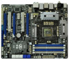
Motherboard Layout 1 2 24.4cm (9.6 in) 34 56 PS2 Mouse PS2 ATX12V1 30.5cm (12.0 in) CPU_FAN1 DDR3 2133 CPU_FAN2 Keyboard Clr CMOS Coaxial SPDIF Optical SPDIF ATXPWR1 DDR3_B1 (64 bit, 240-pin module) DDR3_B2 (64 bit, 240-pin module) DDR3_A2 (64 bit, 240-pin module) DDR3_A1 (64 bit, 240-pin module) USB 3.0 T: USB1 B: USB2 LAN PHY USB 2.0 T: USB2 Top: B: USB3 RJ-45 USB 2.0 T: USB4 B: USB5 LAN USB 3.0 PHY T: USB3 Top: B: USB4 RJ-45 IEEE 1394 eSATA CHA_FAN3 PWR_FAN1 FRONT_1394 1 Dual Channel Top: SIDE SPK Center: SLI/XFIRE_PWR1 REAR SPK FRONT Bottom: CTR BASS Top: LINE IN Center: Bottom: MIC IN SATA2_4_5 SATA2_2_3 SATA3 6Gb/s 48 47 AUDIO PCIE1 CODEC Dual GLAN 46 PCIE2 RoHS 64Mb BIOS CrossFireX 45 PCI1 1394a ErP/EuP Ready CLRCMOS1 44 PCIE3 1 CMOS Intel Super I/O Battery PCI Express 2.0 P67 SATA3_0_1 Front USB 3.0 SATA3_M3_M4 SATA3_M1_M2 43 42 41 40 39 PCIE4 P67 Extreme6 PCI2 Designed in Taipei 1 HDMI_SPDIF1 IR1 PCIE5 HD_AUDIO1 1 FLOPPY1 COM1 USB3_2_3 1 1 Dr. Debug USB 3.0 USB6_7 USB8_9 USB10_11 USB12_13 1 1 1 1 PWRBTN RSTBTN CHA_FAN2 SPEAKER1 1 1 PLED1 CHA_FAN1 PLED PWRBTN 1 HDLED RESET PANEL1 7 8 9 10 11 12 13 14 15 16 17 18 19 20 21 22 23 24 25 26 38 37 36 35 34 33 32 31 30 29 28 27 1 ATX 12V Power Connector (ATX12V1) 25 Power LED Header (PLED1) 2 1155-Pin CPU Socket 26 Chassis Speaker Header 3 CPU Fan Connector (CPU_FAN2) (SPEAKER 1, White) 4 CPU Fan Connector (CPU_FAN1) 27 System Panel Header (PANEL1, White) 5 2 x 240-pin DDR3 DIMM Slots 28 Chassis Fan Connector (CHA_FAN1) (Dual Channel: DDR3_A1, DDR3_B1, Blue) 29 Chassis Fan Connector (CHA_FAN2) 6 2 x 240-pin DDR3 DIMM Slots 30 USB 2.0 Header (USB12_13, Blue) (Dual Channel: DDR3_A2, DDR3_B2, White) 31 USB 2.0 Header (USB10_11, Blue) 7 ATX Power Connector (ATXPWR1) 32 Clear CMOS Jumper (CLRCMOS1) 8 Front Panel IEEE 1394 Header 33 USB 2.0 Header (USB8_9, Blue) (FRONT_1394, White) 34 USB 2.0 Header (USB6_7, Blue) 9 Power Fan Connector (PWR_FAN1) 35 USB 3.0 Header (USB3_2_3, Light Blue) 10 Chassis Fan Connector (CHA_FAN3) 36 COM Port Header (COM1) 11 SATA2 Connector (SATA2_5, Blue) 37 Floppy Connector (FLOPPY1) 12 SATA2 Connector (SATA2_4, Blue) 38 Front Panel Audio Header 13 SATA2 Connector (SATA2_3, Blue) (HD_AUDIO1, White) 14 SATA2 Connector (SATA2_2, Blue) 39 Infrared Module Header (IR1) 15 SATA3 Connector (SATA3_1, White) 40 PCI Express 2.0 x16 Slot (PCIE5, Blue) 16 SATA3 Connector (SATA3_0, White) 41 HDMI_SPDIF Header 17 SATA3 Connector (SATA3_M2, White) (HDMI_SPDIF1, White) 18 SATA3 Connector (SATA3_M1, White) 42 PCI Slot (PCI2) 19 SATA3 Connector (SATA3_M4, White) 43 PCI Express 2.0 x16 Slot (PCIE4, Blue) 20 SATA3 Connector (SATA3_M3, White) 44 PCI Express 2.0 x1 Slot (PCIE3, White) 21 Dr. Debug 45 PCI Slot (PCI1) 22 Intel P67 Chipset 46 PCI Express 2.0 x16 Slot (PCIE2, Blue) 23 Reset Switch (RSTBTN) 47 PCI Express 2.0 x1 Slot (PCIE1, White) 24 Power Switch (PWRBTN) 48 SLI / XFIRE Power Connector 2 ASRock P67 Extreme6 Motherboard English
-
 1
1 -
 2
2 -
 3
3 -
 4
4 -
 5
5 -
 6
6 -
 7
7 -
 8
8 -
9
-
10
-
11
-
12
-
13
-
14
-
15
-
16
-
17
-
18
-
19
-
20
-
21
-
22
-
23
-
24
-
25
-
26
-
27
-
28
-
29
-
30
-
31
-
32
-
33
-
34
-
35
-
36
-
37
-
38
-
39
-
40
-
41
-
42
-
43
-
44
-
45
-
46
-
47
-
48
-
49
-
50
-
51
-
52
-
53
-
54
-
55
-
56
-
57
-
58
-
59
-
60
-
61
-
62
-
63
-
64
-
65
-
66
-
67
-
68
-
69
-
70
-
71
-
72
-
73
-
74
-
75
-
76
-
77
-
78
-
79
-
80
-
81
-
82
-
83
-
84
-
85
-
86
-
87
-
88
-
89
-
90
-
91
-
92
-
93
-
94
-
95
-
96
-
97
-
98
-
99
-
100
-
101
-
102
-
103
-
104
-
105
-
106
-
107
-
108
-
109
-
110
-
111
-
112
-
113
-
114
-
115
-
116
-
117
-
118
-
119
-
120
-
121
-
122
-
123
-
124
-
125
-
126
-
127
-
128
-
129
-
130
-
131
-
132
-
133
-
134
-
135
-
136
-
137
-
138
-
139
-
140
-
141
-
142
-
143
-
144
-
145
-
146
-
147
-
148
-
149
-
150
-
151
-
152
-
153
-
154
-
155
-
156
-
157
-
158
-
159
-
160
-
161
-
162
-
163
-
164
-
165
-
166
-
167
-
168
-
169
-
170
-
171
-
172
-
173
-
174
-
175
-
176
-
177
-
178
-
179
-
180
-
181
-
182
-
183
-
184
-
185
-
186
-
187
-
188
-
189
-
190
-
191
-
192
-
193
-
194
-
195
-
196
-
197
-
198
-
199
-
200
-
201
-
202
-
203
-
204
-
205
-
206
-
207
-
208
-
209
-
210
-
211
-
212
-
213
-
214
-
215
-
216
-
217
-
218
-
219
-
220
-
221
-
222
-
223
-
224
-
225
-
226
-
227
-
228
-
229
-
230
-
231
-
232
-
233
-
234
-
235
-
236
-
237
-
238
-
239
-
240
-
241
-
242
-
243
-
244
-
245
-
246
-
247
-
248
-
249
-
250
-
251
-
252
-
253
-
254
-
255
-
256
-
257
-
258
-
259
-
260
-
261
-
262
-
263
-
264
-
265
-
266
-
267
-
268
-
269
-
270
-
271
-
272
-
273
-
274
-
275
-
276
-
277
-
278
-
279
-
280
-
281
-
282
-
283
-
284
-
285
-
286
-
287
-
288
-
289
-
290
-
291
-
292
-
293
-
294
-
295
-
296
-
297
-
298
-
299
-
300
-
301
-
302
-
303
-
304
-
305
-
306
-
307
-
308
-
309
-
310
-
311
-
312
 |
 |