ASRock P67 Pro3 SE User Manual
ASRock P67 Pro3 SE Manual
 |
View all ASRock P67 Pro3 SE manuals
Add to My Manuals
Save this manual to your list of manuals |
ASRock P67 Pro3 SE manual content summary:
- ASRock P67 Pro3 SE | User Manual - Page 1
P67 Pro3 SE User Manual Version 1.0 Published March 2011 Copyright©2011 ASRock INC. All rights reserved. 1 - ASRock P67 Pro3 SE | User Manual - Page 2
pro ts, loss of business, loss of data, interruption of business and the like), even if ASRock has been advised of the possibility of such damages arising from any defect or error in the manual ONLY The Lithium battery adopted on this motherboard contains Perchlorate, a toxic substance controlled in - ASRock P67 Pro3 SE | User Manual - Page 3
Swap Functions for SATA3 HDDs .... 34 2.16 SATA / SATAII / SATA3 HDD Hot Plug Feature and Operation Guide 35 2.17 Driver Installation Guide 37 2.18 Installing Windows® 7 / 7 64-bit / VistaTM / VistaTM 64-bit With RAID Functions 37 2.19 Installing Windows® 7 / 7 64-bit / VistaTM / VistaTM 64-bit - ASRock P67 Pro3 SE | User Manual - Page 4
SETUP UTILITY 40 3.1 Introduction 40 3.1.1 UEFI Menu Bar 40 3.1.2 Navigation Keys 41 3.2 Main Screen 41 3.3 OC Tweaker Screen 42 3.4 Advanced Screen 46 3.4.1 CPU Software Support 59 4.1 Install Operating System 59 4.2 Support CD Information 59 4.2.1 Running Support CD 59 4.2.2 Drivers Menu - ASRock P67 Pro3 SE | User Manual - Page 5
Contents ASRock P67 Pro3 SE Motherboard (ATX Form Factor: 12.0-in x 7.5-in, 30.5 cm x 19.1 cm) ASRock P67 Pro3 SE Quick Installation Guide ASRock P67 Pro3 SE Support CD 2 x Serial ATA (SATA) Data Cables (Optional) 1 x I/O Panel Shield ASRock Reminds You... To get better performance in Windows - ASRock P67 Pro3 SE | User Manual - Page 6
1.2 Specifications Platform CPU Chipset Memory Expansion Slot Audio LAN Rear Panel I/O - ATX Form Factor: 12.0-in x 7.5-in, 30.5 cm x 19.1 cm - All Solid Capacitor design (100% Japan-made high-quality Conductive Polymer Capacitors) - Supports 2nd Generation Intel® CoreTM i7 / i5 / i3 in LGA1155 - ASRock P67 Pro3 SE | User Manual - Page 7
64Mb AMI BIOS - AMI UEFI Legal BIOS with GUI support - Supports "Plug and Play" - ACPI 1.1 Compliance Wake Up Events - Supports jumperfree - SMBIOS 2.3.1 Support - DRAM, PCH, CPU PLL, VTT, VCCSA Voltage Multi-adjustment - Drivers, Utilities, AntiVirus Software (Trial Version), ASRock Software Suite - ASRock P67 Pro3 SE | User Manual - Page 8
visit our website: http://www.asrock.com WARNING Please realize that there is a certain risk involved with overclocking, including adjusting the setting in the BIOS, applying Untied Overclocking Technology, or using the third-party overclocking tools. Overclocking may affect your system stability - ASRock P67 Pro3 SE | User Manual - Page 9
overclock to 2133 and 1866. 4. Due to the operating system limitation, the actual memory size may be less than 4GB for the reservation for system usage under Windows® 7 / VistaTM / XP. For Windows® OS with 64-bit CPU, there is no such limitation. 5. For microphone input, this motherboard supports - ASRock P67 Pro3 SE | User Manual - Page 10
40% faster than before. ASRock APP Charger allows you to quickly charge many Apple devices simultaneously and even supports continuous charging when your PC enters into Standby mode (S1), Suspend to RAM (S3), hibernation mode (S4) or power off (S5). With APP Charger driver installed, you can easily - ASRock P67 Pro3 SE | User Manual - Page 11
to adopt three different CPU cooler types, Socket LGA 775, LGA 1155 and LGA 1156. Please be noticed that not all the 775 and 1156 CPU Fan can be 1.00W in off mode condition. To meet EuP standard, an EuP ready motherboard and an EuP ready power supply are required. According to Intel's suggestion, - ASRock P67 Pro3 SE | User Manual - Page 12
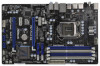
1 64Mb BIOS USB12_13 1 PANEL1 PLED PWRBTN 1 HDLED RESET CHA_FAN3 PLED1 1 SPEAKER1 1 CHA_FAN2 14 15 16 26 25 24 23 22 21 20 19 18 17 1 CPU Fan Connector (CPU_FAN1) 19 System Panel Header (PANEL1, White) 2 1155-Pin CPU Socket 20 USB 2.0 Header (USB12_13, Blue) 3 ATX 12V Power - ASRock P67 Pro3 SE | User Manual - Page 13
1.4 I/O Panel 1 2 3 6 4 7 5 8 15 14 13 12 1 PS/2 Mouse Port (Green) * 2 LAN RJ-45 Port 3 Side Speaker (Gray) 4 Rear Speaker (Black) 5 Central / Bass (Orange) 6 Line In (Light Blue) ** 7 Front Speaker (Lime) 8 Microphone (Pink) 11 10 9 9 USB 2.0 Ports (USB01) 10 USB 3.0 Ports (USB67) 11 - ASRock P67 Pro3 SE | User Manual - Page 14
To enable Multi-Streaming function, you need to connect a front panel audio cable to the front panel audio header. After restarting your computer, you will nd "Mixer" tool on your system. Please select "Mixer ToolBox" , click "Enable playback multi-streaming", and click "ok". Choose "2CH", "4CH - ASRock P67 Pro3 SE | User Manual - Page 15
Precautions Take note of the following precautions before you install motherboard components or change any motherboard settings. 1. Unplug the power cord from the wall socket before touching any component. 2. To avoid damaging the motherboard components due to static electricity, NEVER place your - ASRock P67 Pro3 SE | User Manual - Page 16
Socket Body 1155-Pin Socket Overview Before you insert the 1155-Pin CPU into the socket, please check if the CPU surface is unclean or if there is any bent pin on the socket. Do not force to insert the CPU into the socket 2. This cap must be placed if returning the motherboard for after service. 16 - ASRock P67 Pro3 SE | User Manual - Page 17
key Pin1 Pin1 orientation key notch 1155-Pin CPU alignment key 1155-Pin Socket For proper inserting, please ensure to match the two orientation key notches of the CPU with the two alignment keys of the socket. Step 3-3. Carefully place the CPU into the socket by using a purely vertical motion - ASRock P67 Pro3 SE | User Manual - Page 18
operation or contact other components. Please be noticed that this motherboard supports Combo Cooler Option (C.C.O.), which provides the exible option to adopt three different CPU cooler types, Socket LGA 775, LGA 1155 and LGA 1156. The white throughholes are for Socket LGA 1155/1156 CPU fan. 18 - ASRock P67 Pro3 SE | User Manual - Page 19
Memory Modules (DIMM) This motherboard provides four 240-pin DDR3 (Double Data Rate 3) DIMM slots, and supports Dual Channel Memory Technology. module or three memory modules are installed in the DDR3 DIMM slots on this motherboard, it is unable to activate the Dual Channel Memory Technology. 3. If a - ASRock P67 Pro3 SE | User Manual - Page 20
matches the break on the slot. notch break notch break The DIMM only ts in one correct orientation. It will cause permanent damage to the motherboard and the DIMM if you force the DIMM into the slot at incorrect orientation. Step 3. Firmly insert the DIMM into the slot until the retaining - ASRock P67 Pro3 SE | User Manual - Page 21
of the expansion card and make necessary hardware settings for the card before you start the installation. Remove the system unit cover (if your motherboard is already installed in a chassis). Remove the bracket facing the slot that you intend to use. Keep the screws for later use. Align the - ASRock P67 Pro3 SE | User Manual - Page 22
3D application. Currently CrossFireXTM feature is supported with Windows® XP with Service Pack 2 / VistaTM / 7 OS. Quad CrossFireXTM feature are supported with Windows® VistaTM / 7 OS only. Please check AMD website for ATITM CrossFireXTM driver updates. 1. If a customer incorrectly con gures their - ASRock P67 Pro3 SE | User Manual - Page 23
Bridge is provided with the graphics card you purchase, not bundled with this motherboard. Please refer to your graphics card vendor for details.) CrossFire Bridge or Step 3. Connect the DVI monitor cable to the DVI connector on the Radeon graphics card on PCIE2 slot. (You may use the DVI - ASRock P67 Pro3 SE | User Manual - Page 24
to installation. Please check AMD website for ATITM driver updates. Step 3. Step 4. Step 5. Install the required drivers to your system. For Windows® XP OS: A. ATITM recommends Windows® XP Service Pack 2 or higher to be installed (If you have Windows® XP Service Pack 2 or higher installed in your - ASRock P67 Pro3 SE | User Manual - Page 25
please check AMD website for updates and details. 2.8 Surround Display Feature This motherboard supports Surround Display upgrade. With the external add-on PCI Express VGA cards, you can easily enjoy the bene ts of Surround Display feature. For the detailed instruction, please refer to the document - ASRock P67 Pro3 SE | User Manual - Page 26
IRRX ATX+ different angles 1. Only one of the front USB port can support support Hot-Plug function. Please install it before you boot the system. * ASRock Smart Remote is only supported by some of ASRock motherboards. Please refer to ASRock website for the motherboard support list: http://www.asrock - ASRock P67 Pro3 SE | User Manual - Page 27
. To clear and reset the system parameters to default setup, please turn off the computer and unplug the power updating the BIOS, you must boot up the system rst, and then shut it down before you do the clear-CMOS action. Please be noted that the password, date, time, user default pro le, 1394 GUID - ASRock P67 Pro3 SE | User Manual - Page 28
caps over the headers and connectors will cause permanent damage of the motherboard! Serial ATAII Connectors (SATA2_2: see p.12, No. 8) (SATA2_3 SATA2_2 SATA2_5 SATA2_3 These four Serial ATAII (SATAII) connectors support SATA data cables for internal storage devices. The current SATAII interface - ASRock P67 Pro3 SE | User Manual - Page 29
IRTX IRRX ATX+5VSB This header supports an supports Jack Sensing, but the panel wire on the chassis must support HDA to function correctly. Please follow the instruction in our manual and chassis manual Windows® XP / XP 64-bit OS: Select "Mixer". Select "Recorder". Then click "FrontMic". For Windows - ASRock P67 Pro3 SE | User Manual - Page 30
activity LED on the chassis front panel. The LED is on when the hard drive is reading or writing data. The front panel design may differ by chassis. A front panel module mainly consists of power switch, reset switch, power LED, hard drive activity LED, speaker and etc. When connecting your chassis - ASRock P67 Pro3 SE | User Manual - Page 31
to the ground pin. Though this motherboard provides 4-Pin CPU fan (Quiet Fan) support, the 3-Pin CPU fan still can work successfully even without the fan speed control function. If you plan to connect the 3-Pin CPU fan to the CPU fan connector on this motherboard, please connect it to Pin 1-3. Pin - ASRock P67 Pro3 SE | User Manual - Page 32
Serial port Header (9-pin COM1) (see p.12 No. 24) HDMI_SPDIF Header (2-pin HDMI_SPDIF1) (see p.12 No. 27) 1 GND SPDIFOUT This COM1 header supports a serial port module. HDMI_SPDIF header, providing SPDIF audio output to HDMI VGA card, allows the system to connect HDMI Digital TV/ projector/LCD - ASRock P67 Pro3 SE | User Manual - Page 33
motherboard adopts Intel® P67 chipset that supports Serial ATA (SATA) / Serial ATAII (SATAII) hard disks and RAID (RAID 0, RAID 1, RAID 10, RAID 5 and Intel Rapid Storage) functions. You may install SATA / SATAII hard disks on this motherboard for internal storage devices. This section will guide - ASRock P67 Pro3 SE | User Manual - Page 34
Hot Swap Functions for SATA / SATAII HDDs This motherboard supports Hot Plug and Hot Swap functions for SATA / SATAII in RAID / AHCI mode. Intel® P67 chipset provides hardware support for Advanced Host controller Interface (AHCI), a new programming interface for SATA host controllers developed thru - ASRock P67 Pro3 SE | User Manual - Page 35
is installed into system properly. The latest SATA / SATAII / SATA3 driver is available on our support website: www.asrock.com 4. Make sure to use the SATA power cable & data cable, which are from our motherboard package. 5. Please follow below instructions step by step to reduce the risk of HDD - ASRock P67 Pro3 SE | User Manual - Page 36
do follow below instruction sequence to process the Hot Plug, improper procedure will cause the SATA / SATAII / SATA3 HDD damage and data loss. Step 1 Please connect SATA power cable 1x4-pin end Step 2 Connect SATA data cable to (White) to the power supply 1x4-pin cable. the motherboard's SATAII - ASRock P67 Pro3 SE | User Manual - Page 37
is not supported under Windows® XP / XP 64-bit OS. STEP 1: Set up UEFI. A. Enter UEFI SETUP UTILITY Advanced screen SATA Con guration. B. Set the option "SATA Mode" to [RAID] for SATA2 ports. Set the option "SATA3 Mode" to [RAID] for SATA3 ports. STEP 2: Use "RAID Installation Guide" to set RAID con - ASRock P67 Pro3 SE | User Manual - Page 38
/ SATA3 HDDs without RAID functions, please follow below steps. AHCI mode is not supported under Windows® XP / XP 64-bit OS. Using SATA / SATAII / SATA3 HDDs without NCQ function STEP 1: Set up UEFI. A. Enter UEFI SETUP UTILITY Advanced screen SATA Con guration. B. Set the option "SATA Mode" to [IDE - ASRock P67 Pro3 SE | User Manual - Page 39
STA3 HDDs without NCQ function STEP 1: Set up UEFI. A. Enter UEFI SETUP UTILITY Advanced screen SATA Con guration. B. Set the option "SATA Mode" to [IDE] for SATA2 ports. Set the option "SATA3 Mode" to [IDE] for SATA3 ports. STEP 2: Install Windows® 7 / 7 64-bit / VistaTM / VistaTM 64-bit OS on your - ASRock P67 Pro3 SE | User Manual - Page 40
motherboard stores the UEFI SETUP UTILITY. You may run the UEFI SETUP UTILITY when you start up the computer. Please press or during the Power-On-Self-Test (POST) to enter the UEFI SETUP UTILITY, otherwise, POST will continue with its test being updated, the following UEFI setup screens - ASRock P67 Pro3 SE | User Manual - Page 41
the selected screen To display the General Help Screen To load optimal default values for all the settings To save changes and exit the UEFI SETUP UTILITY To jump to the Exit Screen or exit the current screen 3.2 Main Screen When you enter the UEFI - ASRock P67 Pro3 SE | User Manual - Page 42
OC Tweaker Screen In the OC Tweaker screen, you can set up overclocking features. Load Optimized CPU OC Setting Use this item to load optimized CPU overclocking setting. Please note that overclocking may cause damage to your components and motherboard. It should be done at your own risk and expense - ASRock P67 Pro3 SE | User Manual - Page 43
le 1] and [Pro le 2]. The default value is [Auto]. DRAM Frequency If [Auto] is selected, the motherboard will detect the memory module(s) inserted and assigns appropriate frequency automatically. CAS# Latency (tCL) Use this item to change CAS# Latency (tCL) Auto/Manual setting. The default is [Auto - ASRock P67 Pro3 SE | User Manual - Page 44
[Auto]. Read to Precharge (tRTP) Use this item to change Read to Precharge (tRTP) Auto/Manual setting. The default is [Auto]. Four Activate Window (tFAW) Use this item to change Four Activate Window (tFAW) Auto/Manual setting. The default is [Auto]. Memory Fast Boot Use this item to adjust DDR fast - ASRock P67 Pro3 SE | User Manual - Page 45
Offset. The default value is [Auto]. DRAM Voltage Use this to select DRAM Voltage. The default value is [Auto]. CPU PLL Voltage Use this to select CPU PLL Voltage. The default value is [Auto]. VTT Voltage Use this to select VTT Voltage. The default value is [Auto]. PCH Voltage Use this to - ASRock P67 Pro3 SE | User Manual - Page 46
con gurations for the following items: CPU Con guration, North Bridge Con guration, ASRock Instant Flash ASRock Instant Flash is a UEFI flash utility embedded in Flash ROM. This convenient UEFI update tool allows you to update system UEFI without entering operating systems rst like MS-DOS or Windows - ASRock P67 Pro3 SE | User Manual - Page 47
(C1). The C1 state is supported through the native processor instructions HLT and MWAIT and requires no hardware support from the chipset. In the C1 power state, the processor maintains the context of the system caches. CPU C3 State Support Use this to enable or disable CPU C3 (ACPI C2) report to - ASRock P67 Pro3 SE | User Manual - Page 48
with "No Execute (NX) Memory Protection" can prevent data pages from being used by malicious software to execute code. This option will be hidden if the current CPU does not support No-Excute Memory Protection. Local x2APIC Use this to enable or disable Local x2APIC. The default value is [Disabled - ASRock P67 Pro3 SE | User Manual - Page 49
3.4.2 North Bridge Configuration Low MMIO Align Low MMIO resources align at 64MB/1024MB. The default value is [64MB]. VT-d Use this to enable or disable Intel® VT-d technology (Intel® Virtualization Technology for Directed I/O). The default value of this feature is [Disabled]. 49 - ASRock P67 Pro3 SE | User Manual - Page 50
system starts to boot up when the power recovers. Deep Sx Mobile platforms support Deep S4/S5 in DC only and desktop platforms support Deep S4/S5 in AC only. Con guration options: [Disabled], [Enabled in to [Enabled] if you plan to use this motherboard to submit Windows® VistaTM certi cation. 50 - ASRock P67 Pro3 SE | User Manual - Page 51
supports NCQ and other new features that will improve SATA disk performance but IDE mode does not have these advantages. SATA Controller 0 Please select [Compatible] when you install legacy OS. If native OS (Windows SATA3 mode. Conguration options: [RAID Mode], [IDE Mode], [AHCI Mode] and [Disabled]. - ASRock P67 Pro3 SE | User Manual - Page 52
3.4.5 Super IO Configuration Serial Port Use this item to enable or disable the onboard serial port. Serial Port Address Use this item to set the address for the onboard serial port. Con guration options: [3F8 / IRQ4] and [3E8 / IRQ4]. Infrared Port Use this item to enable or disable the onboard - ASRock P67 Pro3 SE | User Manual - Page 53
3.4.6 ACPI Configuration Suspend to RAM Use this item to select whether to auto-detect or disable the Suspend-toRAM feature. Select [Auto] will enable this feature if the OS supports it. Check Ready Bit Use this item to enable or disable the feature Check Ready Bit. PS/2 Keyboard Power On Use this - ASRock P67 Pro3 SE | User Manual - Page 54
compatibility issue, it is recommended to select [Disabled] to enter OS. [UEFI Setup Only] - USB devices are allowed to use only under UEFI setup and Windows / Linux OS. Legacy USB 3.0 Support Use this option to enable or disable legacy support for USB 3.0 devices. The default value is [Enabled]. 54 - ASRock P67 Pro3 SE | User Manual - Page 55
CPU temperature, motherboard temperature, CPU fan speed, chassis fan speed, and the critical voltage. CPU Fan 1 & 2 Setting This allows you to set the CPU the chassis fan 3 speed. Con guration options: [Full On] and [Manual Mode]. The default is value [Full On]. Over Temperature Protection Use this - ASRock P67 Pro3 SE | User Manual - Page 56
will display the available devices on your system for you to con gure the boot settings and the boot priority. Setup Prompt Timeout This shows the number of seconds to wait for setup activation key. 65535(0XFFFF) means inde nite waiting. Bootup Num-Lock If this item is set to [On], it - ASRock P67 Pro3 SE | User Manual - Page 57
3.7 Security Screen In this section, you may set or change the supervisor/user password for the system. For the user password, you may also clear it. 57 - ASRock P67 Pro3 SE | User Manual - Page 58
pop-out the following message, "Discard changes?" Select [OK] to discard all changes. Load UEFI Defaults Load UEFI default values for all the setup questions. F9 key can be used for this operation. Launch EFI Shell from filesystem device Attempts to Launch EFI Shell application (Shell64.efi) from - ASRock P67 Pro3 SE | User Manual - Page 59
settings and hardware options vary, use the setup procedures in this chapter for general reference only. Refer to your OS documentation for more information. 4.2 Support CD Information The Support CD that came with the motherboard contains necessary drivers and useful utilities that enhance the - ASRock P67 Pro3 SE | User Manual - Page 60
HDD Larger Than 2TB This motherboard is adopting UEFI BIOS that allows Windows® OS to be installed on a large size HDD (>2TB). Please follow below procedure to install the operating system. 1. Please make sure to use Windows® VistaTM 64-bit (with SP1 or above) or Windows® 7 64-bit. 2. Press or
-
 1
1 -
 2
2 -
 3
3 -
 4
4 -
 5
5 -
 6
6 -
 7
7 -
8
-
9
-
10
-
11
-
12
-
13
-
14
-
15
-
16
-
17
-
18
-
19
-
20
-
21
-
22
-
23
-
24
-
25
-
26
-
27
-
28
-
29
-
30
-
31
-
32
-
33
-
34
-
35
-
36
-
37
-
38
-
39
-
40
-
41
-
42
-
43
-
44
-
45
-
46
-
47
-
48
-
49
-
50
-
51
-
52
-
53
-
54
-
55
-
56
-
57
-
58
-
59
-
60
 |
 |
1
P67 Pro3 SE
User Manual
Version 1.0
Published March 2011
Copyright©2011 ASRock INC. All rights reserved.