ASRock P75 Pro3 User Manual
ASRock P75 Pro3 Manual
 |
View all ASRock P75 Pro3 manuals
Add to My Manuals
Save this manual to your list of manuals |
ASRock P75 Pro3 manual content summary:
- ASRock P75 Pro3 | User Manual - Page 1
P75 Pro3 User Manual Version 1.0 Published August 2012 Copyright©2012 ASRock INC. All rights reserved. 1 - ASRock P75 Pro3 | User Manual - Page 2
backup purpose, without written consent of ASRock Inc. Products and corporate names appearing in this manual may or may not be registered trademarks The Lithium battery adopted on this motherboard contains Perchlorate, a toxic substance controlled /perchlorate" ASRock Website: http://www.asrock.com 2 - ASRock P75 Pro3 | User Manual - Page 3
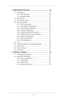
16 2.4 Installation of Heatsink and CPU fan 18 2.5 Installation of Memory Modules (DIMM 19 2.6 Expansion Slots (PCI and PCI Express Slots 20 2.7 CrossFireXTM and Quad CrossFireXTM Operation Guide. 21 2.8 ASRock Smart Remote Installation Guide 25 2.9 Jumpers Setup 27 2.10 Onboard Headers and - ASRock P75 Pro3 | User Manual - Page 4
CPU Configuration 46 3.4.2 North Bridge Configuration 48 3.4.3 South Bridge Configuration 49 3.4.4 Storage Configuration 50 3.4.5 Intel(R) Rapid Start Technology 51 3.4.6 Intel Support 62 4.1 Install Operating System 62 4.2 Support CD Information 62 4.2.1 Running Support CD 62 4.2.2 Drivers - ASRock P75 Pro3 | User Manual - Page 5
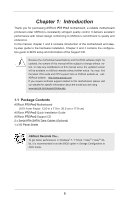
guide to BIOS setup and information of the Support CD. Because the motherboard specifications and the BIOS software might be updated, the content of this manual will be subject to change without notice. In case any modifications of this manual occur, the updated version will be available on ASRock - ASRock P75 Pro3 | User Manual - Page 6
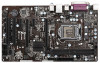
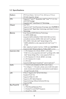
CPU Chipset Memory Expansion Slot Audio LAN Rear Panel I/O - ATX Form Factor: 12.0-in x 7.0-in, 30.5 cm x 17.8 cm - All Solid Capacitor design - Supports 3rd and 2nd Generation Intel® CoreTM i7 / i5 / i3 in LGA1155 Package - Supports Intel® Turbo Boost 2.0 Technology - Intel® B75 - Supports Intel - ASRock P75 Pro3 | User Manual - Page 7
Support - CPU Core, DRAM, 1.8V PLL, VTT, VCCSA Voltage Multi-adjustment - Drivers, Utilities, AntiVirus Software (Trial Version), CyberLink MediaEspresso 6.5 Trial, ASRock MAGIX Multimedia Suite - OEM - CPU Temperature Sensing - Chassis Temperature Sensing - CPU/Chassis/Power Fan Tachometer - CPU - ASRock P75 Pro3 | User Manual - Page 8
, please visit our website: http://www.asrock.com WARNING Please realize that there is a certain risk involved with overclocking, including adjusting the setting in the BIOS, applying Untied Overclocking Technology, or using third-party overclocking tools. Overclocking may affect your system - ASRock P75 Pro3 | User Manual - Page 9
system. In Fan Control, it shows the fan speed and temperature for you to adjust. In Overclocking, you are allowed to overclock CPU frequency for optimal F2> key to enter into the BIOS setup menu to access ASRock Instant Flash. Just launch this tool and save the new BIOS file to your USB flash drive, - ASRock P75 Pro3 | User Manual - Page 10
currently. ASRock XFast RAM ASRock XFast RAM is a new function that is included into ASRock Extreme Tuning Utility (AXTU). It fully utilizes the memory space that cannot be used under Windows® OS 32-bit CPU. ASRock XFast RAM shortens the loading time of previously visited websites, making - ASRock P75 Pro3 | User Manual - Page 11
loss occurs during the BIOS update process, ASRock Crashless BIOS will automatically finish the BIOS update procedure after regaining power. Please note that BIOS files need to be placed in the root directory of your USB disk. Only USB2.0 ports support this feature. ASRock On/Off Play Technology - ASRock P75 Pro3 | User Manual - Page 12
types, Socket LGA 775, LGA 1155 and LGA 1156. Please be noticed that not all the 775 and 1156 CPU Fan can be used. ASRock Good Night LED ASRock Good Night LED technology can offer you a better environment by extinguishing the unessential LED. By enabling Good Night LED in BIOS, the Power / HDD - ASRock P75 Pro3 | User Manual - Page 13
11 12 22 21 20 1918 17 1 CPU Fan Connector (CPU_FAN1) 2 1155-Pin CPU Socket 3 ATX 12V Power Connector (ATX12V1) 4 2 x 240-pin DDR3 DIMM Slots (DDR3_A1, DDR3_B1, Black) 5 ATX Power Connector (ATXPWR1) 6 USB 3.0 Header (USB3_2_3, Black) 7 Intel B75 Chipset 8 SPI Flash Memory (64Mb) 9 SATA3 Connector - ASRock P75 Pro3 | User Manual - Page 14
connection Blinking Data Activity Orange 100Mbps connection On Link Green 1Gbps connection LAN Port ** If you enable Multi-Streaming function, this motherboard can support up to 5.1 CH audio only. To enable Multi-Streaming function, you need to connect a front panel audio cable to the front - ASRock P75 Pro3 | User Manual - Page 15
Take note of the following precautions before you install motherboard components or change any motherboard settings. 1. Unplug the power cord from the wall socket before touching any components. 2. To avoid damaging the motherboard's components due to static electricity, NEVER place your - ASRock P75 Pro3 | User Manual - Page 16
Installation For the installation of Intel 1155-Pin CPU, please follow the steps below. Load Plate Load Lever Contact Array Socket Body 1155-Pin Socket Overview Before you insert the 1155-Pin CPU into the socket, please check if the CPU surface is unclean or if there are any bent pins in the - ASRock P75 Pro3 | User Manual - Page 17
key Pin1 Pin1 orientation key notch 1155-Pin CPU alignment key 1155-Pin Socket For proper inserting, please ensure to match the two orientation key notches of the CPU with the two alignment keys of the socket. Step 3-3. Carefully place the CPU into the socket by using a purely vertical motion - ASRock P75 Pro3 | User Manual - Page 18
fan operation or contact other components. Please be noticed that this motherboard supports Combo Cooler Option (C.C.O.), which provides flexible options to adopt three different CPU cooler types, Socket LGA 775, LGA 1155 and LGA 1156. The white throughholes are for Socket LGA 1155/1156 CPU fan - ASRock P75 Pro3 | User Manual - Page 19
2.5 Installation of Memory Modules (DIMM) This motherboard provides two 240-pin DDR3 (Double Data Rate 3) DIMM slots, and supports Dual Channel Memory Technology. For dual channel configuration, you always need to install two identical (the same brand, speed, size and chiptype) memory modules in - ASRock P75 Pro3 | User Manual - Page 20
to the motherboard's chassis fan connector (CHA_FAN1 or CHA_FAN2) when using multiple graphics cards for better thermal environment. 4. Only PCIE1 slot supports Gen 3 speed. To run the PCI Express in Gen 3 speed, please install an Ivy Bridge CPU. If you install a Sandy Bridge CPU, the PCI Express - ASRock P75 Pro3 | User Manual - Page 21
Guide This motherboard supports supported by Windows® XP with Service Pack 2 / VistaTM / 7 OS. Quad CrossFireXTM is supported by Windows® VistaTM / 7 OS only. Please check AMD's website for AMD CrossFireXTM driver refer to AMD graphics card manuals for detailed installation guide. Step 1. Insert one - ASRock P75 Pro3 | User Manual - Page 22
on the top of the Radeon graphics cards. (The CrossFire Bridge is provided with the graphics card you purchase, not bundled with this motherboard. Please refer to your graphics card vendor for details.) CrossFire Bridge or Step 3. Connect the DVI monitor cable to the DVI connector on - ASRock P75 Pro3 | User Manual - Page 23
to uninstall any previously installed Catalyst drivers prior to installation. Please check AMD's website for AMD driver updates. Step 3. Step 4. Step 5. Install the required drivers to your system. For Windows® XP OS: A. AMD recommends Windows® XP Service Pack 2 or higher to be installed - ASRock P75 Pro3 | User Manual - Page 24
used only for identification or explanation and to the owners' benefit, without intent to infringe. * For further information of AMD CrossFireXTM technology, please check AMD's website for updates and details. 24 - ASRock P75 Pro3 | User Manual - Page 25
2.8 ASRock Smart Remote Installation Guide ASRock Smart Remote is only used for ASRock motherboard with CIR header. Please refer to below procedures for the quick installation and usage of ASRock Smart Remote. Step1. Find the CIR header located next to the USB 2.0 header on ASRock motherboard. - ASRock P75 Pro3 | User Manual - Page 26
chassis on the market. 3. The Multi-Angle CIR Receiver does not support Hot-Plug function. Please install it before you boot the system. * ASRock Smart Remote is only supported by some of ASRock motherboards. Please refer to ASRock website for the motherboard support list: http://www.asrock.com 26 - ASRock P75 Pro3 | User Manual - Page 27
the data in CMOS. To clear and reset the system parameters to default setup, please turn off the computer and unplug the power cord from the power GUID and MAC address will be cleared only if the CMOS battery is removed. If you clear the CMOS, the case open may be detected. Please adjust the BIOS - ASRock P75 Pro3 | User Manual - Page 28
jumper caps over the headers and connectors will cause permanent damage of the motherboard! Serial ATA2 Connectors (SATA2_1: see p.13, No. 15) (SATA2_2: SATA2_4 SATA2_1 SATA2_3 These five Serial ATA2 (SATA2) connectors support SATA data cables for internal storage devices. The current SATA2 - ASRock P75 Pro3 | User Manual - Page 29
one USB 3.0 header on this motherboard. This USB 3.0 header can support two USB 3.0 ports. Infrared Module supports Jack Sensing, but the panel wire on the chassis must support HDA to function correctly. Please follow the instruction in our manual and chassis manual . Adjust "Recording Volume". 29 - ASRock P75 Pro3 | User Manual - Page 30
System Panel Header (9-pin PANEL1) (see p.13, No. 16) This header accommodates several system front panel functions. Connect the power switch, reset switch and system status indicator on the chassis to this header according to the pin assignments below. Note the positive and negative pins before - ASRock P75 Pro3 | User Manual - Page 31
to the ground pin. Though this motherboard provides 4-Pin CPU fan (Quiet Fan) support, the 3-Pin CPU fan still can work successfully even without the fan speed control function. If you plan to connect the 3-Pin CPU fan to the CPU fan connector on this motherboard, please connect it to Pin 1-3. Pin - ASRock P75 Pro3 | User Manual - Page 32
Header (2-pin HDMI_SPDIF1) (see p.13, No. 30 1 GND SPDIFOUT Please connect an ATX 12V power supply to this connector. This motherboard supports CASE OPEN detection feature that detects if the chassis cover has been removed. This feature requires a chassis with chassis intrusion detection - ASRock P75 Pro3 | User Manual - Page 33
/ SATA2 / SATA3 HDDs This motherboard supports Hot Plug for SATA / SATA2 / SATA3 in AHCI mode. Intel® B75 chipset provides hardware support for Advanced Host controller Interface (AHCI), a new programming interface for SATA host controllers developed through a joint industry effort. NOTE What is Hot - ASRock P75 Pro3 | User Manual - Page 34
installed into system properly. The latest SATA / SATA2 / SATA3 driver is available on our support website: www.asrock.com 4. Make sure to use the SATA power cable & data cable, which are from our motherboard package. 5. Please follow below instructions step by step to reduce the risk of HDD crash - ASRock P75 Pro3 | User Manual - Page 35
supply's 1x4-pin cable. Step 2 Connect SATA data cable to the motherboard's SATA2 / SATA3 connector. SATA power cable 1x4-pin power connector ( attention, before you process the Hot Unplug: Please do follow below instruction sequence to process the Hot Unplug, improper procedure will cause the SATA - ASRock P75 Pro3 | User Manual - Page 36
Driver Installation Guide To install the drivers to your system, please insert the support CD to your optical drive first. Then, the drivers compatible to your system can be auto-detected and listed on the support CD driver below. AHCI mode is not supported under Windows® XP / XP 64-bit. Using SATA - ASRock P75 Pro3 | User Manual - Page 37
VistaTM / VistaTM 64-bit OS on your system. Using SATA / SATA2 / SATA3 HDDs without NCQ function STEP 1: Set Up UEFI. A. Enter UEFI SETUP UTILITY Advanced screen Storage Configuration. B. Set the option "SATA Mode Selection" to [IDE]. STEP 2: Install Windows® 7 / 7 64-bit / VistaTM / VistaTM 64-bit - ASRock P75 Pro3 | User Manual - Page 38
motherboard stores the UEFI SETUP UTILITY. You may run the UEFI SETUP UTILITY when you start up the computer. Please press or during the Power-On-Self-Test (POST) to enter the UEFI SETUP UTILITY, otherwise, POST will continue with its test To set up overclocking features Advanced To set - ASRock P75 Pro3 | User Manual - Page 39
the screen To display the General Help Screen Discard changes and exit the UEFI SETUP UTILITY Load optimal default values for all the settings Save changes and exit the UEFI SETUP UTILITY Print screen Jump to the Exit Screen or exit the current screen 39 - ASRock P75 Pro3 | User Manual - Page 40
3.2 Main Screen When you enter the UEFI SETUP UTILITY, the Main screen will appear and display the system overview. 40 - ASRock P75 Pro3 | User Manual - Page 41
overclocking features. CPU Configuration CPU Ratio Use this item to change the ratio value of this motherboard. Intel SpeedStep Technology Intel SpeedStep technology is Intel's new current CPU does not support Intel SpeedStep technology. Please note that enabling this function may reduce CPU voltage - ASRock P75 Pro3 | User Manual - Page 42
is [Auto]. DRAM Frequency If [Auto] is selected, the motherboard will detect the memory module(s) inserted and assign the appropriate frequency Latency (tCL) Auto/Manual setting. The default is [Auto]. DRAM tRCD Use this item to change RAS# to CAS# Delay (tRCD) Auto/Manual setting. The default is - ASRock P75 Pro3 | User Manual - Page 43
setting. The default is [Auto]. DRAM tRTP Use this item to change Read to Precharge (tRTP) Auto/Manual setting. The default is [Auto]. DRAM tFAW Use this item to change Four Activate Window (tFAW) Auto/Manual setting. The default is [Auto]. DRAM tCWL Use this item to change CAS# Write Latency (tCWL - ASRock P75 Pro3 | User Manual - Page 44
Voltage Offset Use this to select CPU Core Voltage. The default value is [Auto]. DRAM Auto]. PCH Voltage Use this to select PCH Voltage. The default value is [Auto]. CPU PLL Voltage Use this to select CPU PLL Voltage. The default value is [Auto]. VCCSA Voltage Use this to select VCCSA Voltage - ASRock P75 Pro3 | User Manual - Page 45
this section, you may set the configurations for the following items: CPU Configuration, North Bridge Configuration, South Bridge Configuration, Storage Configuration, Intel(R) Rapid Start Technology, Intel(R) Smart Connect Technology, Super IO Configuration, ACPI Configuration and USB Configuration - ASRock P75 Pro3 | User Manual - Page 46
(C1). The C1 state is supported through the native processor instructions HLT and MWAIT and requires no hardware support from the chipset. In the C1 power state, the processor maintains the context of the system caches. CPU C3 State Support Use this to enable or disable CPU C3 (ACPI C2) report to - ASRock P75 Pro3 | User Manual - Page 47
pages from being used by malicious software to execute codes. This option will be hidden if the current CPU does not support No-Excute Memory Protection. Intel Virtualization Technology When this option is set to [Enabled], a VMM (Virtual Machine Architecture) can utilize the additional hardware - ASRock P75 Pro3 | User Manual - Page 48
to select [PCI] or [PCI Express] as the boot graphic adapter priority. The default value is [PCI Express]. VT-d Use this item to enable/disable Intel(R) Virtualization Technology for Directed I/O. PCIE1 Link Speed This allows you to select PCIE1 Link Speed. The default value is [Auto]. 48 - ASRock P75 Pro3 | User Manual - Page 49
On/Off Play first. Onboard LAN This allows you to enable or disable the Onboard LAN feature. Deep Sleep Mobile platforms support Deep S4/S5 in DC only and desktop platforms support Deep S4/S5 in AC only. The default value is [Enabled in S5]. Restore on AC/Power Loss This allows - ASRock P75 Pro3 | User Manual - Page 50
. Configuration options: [IDE Mode], [AHCI Mode] and [Disabled]. The default value is [AHCI Mode]. AHCI (Advanced Host Controller Interface) supports NCQ and other new features that will improve SATA disk performance but IDE mode does not have these advantages. SATA Aggressive Link Power Management - ASRock P75 Pro3 | User Manual - Page 51
Start Technology. Intel(R) Rapid Start Technology is a new zero power hibernation mode which allows users to resume in just 5-6 seconds. The default is [Enabled]. Entry After Select a time to enable RTC wake timer at S3 entry. The default is [10 minutes]. Active Page Threshold Support This allows - ASRock P75 Pro3 | User Manual - Page 52
(R) Smart Connect Technology Intel(R) Smart Connect Technology Use this item to enable or disable Intel(R) Smart Connect Technology. Intel(R) Smart Connect Technology keeps your e-mail and social networks, such as Twitter, Facebook, etc. updated automatically while the computer is in sleep mode. The - ASRock P75 Pro3 | User Manual - Page 53
3.4.7 Super IO Configuration Serial Port Use this item to enable or disable the onboard serial port. Serial Port Address Use this item to set the address for the onboard serial port. Configuration options: [3F8h / IRQ4] and [3E8h / IRQ4]. Infrared Port Use this item to enable or disable the onboard - ASRock P75 Pro3 | User Manual - Page 54
-toRAM feature. Selecting [Auto] will enable this feature if the OS supports it. Check Ready Bit Use this item to enable or disable the feature ]. Please set this option to [Enabled] if you plan to use this motherboard to submit Windows® VistaTM certification. PS/2 Keyboard Power On Use this item to - ASRock P75 Pro3 | User Manual - Page 55
this item to enable or disable the use of USB 3.0 controller. Legacy USB Support Use this option to select legacy support for USB devices. There are four configuration options: [Enabled], [Auto], [Disabled] and [UEFI Setup Only]. The default value is [Enabled]. Please refer to below descriptions for - ASRock P75 Pro3 | User Manual - Page 56
let you easily check your current system configuration in UEFI setup. OMG(Online Management Guard) Administrators are able to establish UEFI without entering operating systems first like MS-DOS or Windows®. Just save the new UEFI file to your USB flash drive, floppy disk or hard drive and launch - ASRock P75 Pro3 | User Manual - Page 57
[Europe], [USA] and [China]. Dehumidifier Function Users may prevent motherboard damages due to dampness by enabling "Dehumidifier Function". When enabling Dehumidifier returns to S4/S5 state. Dehumidifier CPU Fan Setting Use this setting to configure CPU fan speed while "Dehumidifier" is enabled. 57 - ASRock P75 Pro3 | User Manual - Page 58
of the hardware on your system, including the parameters of the CPU temperature, motherboard temperature, CPU fan speed, chassis fan speed, and the critical voltage. CPU Fan 1 Setting This allows you to set CPU fan 1's speed. Configuration options: [Full On] and [Automatic Mode]. The default value - ASRock P75 Pro3 | User Manual - Page 59
boot by using an USB flash drive. [Ultra Fast] - There are a few restrictions. 1. Only supports Windows® 8 UEFI operating system. 2. You will not be able to enter BIOS Setup (Clear CMOS or run XXX utility in Widows® to enter BIOS Setup). 3. If you are using an external graphics card, the VBIOS must - ASRock P75 Pro3 | User Manual - Page 60
ROM]. Full Screen Logo Use this item to enable or disable OEM Logo. The default value is [Enabled]. AddOn ROM Display Use this option to adjust AddOn ROM Display. If you enable the option "Full Screen Logo" but you want to see the AddOn ROM information when the system boots, please - ASRock P75 Pro3 | User Manual - Page 61
following message "Discard changes?" will pop-out. Select [Yes] to discard all changes. Load UEFI Defaults Load UEFI default values for all the setup questions. F9 key can be used for this operation. Launch EFI Shell from filesystem device Attempts to Launch EFI Shell application (Shell64.efi) from - ASRock P75 Pro3 | User Manual - Page 62
settings and hardware options vary, use the setup procedures in this chapter for general reference only. Refer your OS documentation for more information. 4.2 Support CD Information The Support CD that came with the motherboard contains necessary drivers and useful utilities that enhance the - ASRock P75 Pro3 | User Manual - Page 63
a HDD Larger Than 2TB in AHCI Mode This motherboard adopts UEFI BIOS that allows Windows® OS to be installed on a system POST. Set AHCI Mode in UEFI Setup Utility > Advanced > Storage Configuration > SATA Mode. 3. Choose the item "UEFI:xxx" to boot in UEFI Setup Utility > Boot > Boot Option #1. ("
-
 1
1 -
 2
2 -
 3
3 -
 4
4 -
 5
5 -
 6
6 -
 7
7 -
8
-
9
-
10
-
11
-
12
-
13
-
14
-
15
-
16
-
17
-
18
-
19
-
20
-
21
-
22
-
23
-
24
-
25
-
26
-
27
-
28
-
29
-
30
-
31
-
32
-
33
-
34
-
35
-
36
-
37
-
38
-
39
-
40
-
41
-
42
-
43
-
44
-
45
-
46
-
47
-
48
-
49
-
50
-
51
-
52
-
53
-
54
-
55
-
56
-
57
-
58
-
59
-
60
-
61
-
62
-
63
 |
 |

1
P75 Pro3
User Manual
Version 1.0
Published August 2012
Copyright©2012 ASRock INC. All rights reserved.