ASRock X299M Extreme4 Quick Installation Guide
ASRock X299M Extreme4 Manual
 |
View all ASRock X299M Extreme4 manuals
Add to My Manuals
Save this manual to your list of manuals |
ASRock X299M Extreme4 manual content summary:
- ASRock X299M Extreme4 | Quick Installation Guide - Page 1
documentation are furnished for informational use only and subject to change without notice, and should not be constructed as a commitment by ASRock. ASRock assumes no responsibility for any errors or omissions that may appear in this documentation. With respect to the contents of this documentation - ASRock X299M Extreme4 | Quick Installation Guide - Page 2
if the goods fail to be of acceptable quality and the failure does not amount to a major failure. If you require assistance please call ASRock Tel : +886-2-28965588 ext.123 (Standard International call charges apply) Manufactured under license under U.S. Patent Nos: 5,956,674; 5,974,380; 6,487,535 - ASRock X299M Extreme4 | Quick Installation Guide - Page 3
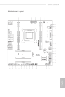
Motherboard Layout X299M Extreme4 USB 2.0 T: USB1 B: USB2 PS2 Keyboard/ Mouse CLRC BTN1 USB 3.1 Gen1 T: USB3_1 DDR4_B1 (64 bit, 288-pin module) DDR4_A1 (64 bit, 288-pin module) ATX12V1 ATX12V2 2066 Socket CPU_FAN1 1 CPU_OPT/WP CHA_FAN1/WP RGB_LED2 ATXPWR1 DDR4_C1 (64 bit, 288-pin module) - ASRock X299M Extreme4 | Quick Installation Guide - Page 4
No. Description 1 2 x 288-pin DDR4 DIMM Slots (DDR4_A1, DDR4_B1) 2 ATX 12V Power Connector (ATX12V1) 3 ATX 12V Power Connector (ATX12V2) 4 2 x 288-pin DDR4 DIMM Slots (DDR4_C1, DDR4_D1) 5 CPU Fan Connector (CPU_FAN1) 6 RGB LED Header (RGB_LED2) 7 CPU Fan / Waterpump Fan Connector (CPU_OPT/WP) 8 - ASRock X299M Extreme4 | Quick Installation Guide - Page 5
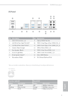
I/O Panel 1 X299M Extreme4 2 3 46 57 16 15 14 13 12 10 98 11 No. Description 1 USB 2.0 Ports (USB_1_2) 2 LAN RJ-45 Port (Intel® I211AT)* 3 LAN RJ-45 Port ( - ASRock X299M Extreme4 | Quick Installation Guide - Page 6
** If you use a 2-channel speaker, please connect the speaker's plug into "Front Speaker Jack". See the table below for connection details in accordance with the type of speaker you use. Audio Output Channels 2 4 6 8 Front Speaker (No. 7) V V V V Rear Speaker (No. 5) -V V V Central / Bass (No. - ASRock X299M Extreme4 | Quick Installation Guide - Page 7
VGA cards and CPU support list on ASRock's website as well. ASRock website http://www.asrock.com. 1.1 Package Contents • ASRock X299M Extreme4 Motherboard (Micro ATX Form Factor) • ASRock X299M Extreme4 Quick Installation Guide • ASRock X299M Extreme4 Support CD • 1 x I/O Panel Shield • 2 x Serial - ASRock X299M Extreme4 | Quick Installation Guide - Page 8
• Micro ATX Form Factor CPU • Supports Intel® CoreTM X-Series Processor Family for the LGA 2066 Socket • Digi Power design • 11 Power Phase design • Supports Intel® Turbo Boost Max Technology 3.0 * Please note that the 4-Core processors only support Intel® Turbo Boost Technology 2.0. Chipset - ASRock X299M Extreme4 | Quick Installation Guide - Page 9
X299M Extreme4 • Supports AMD Quad CrossFireXTM and CrossFireXTM • Supports NVIDIA® Quad SLITM and SLITM • 15μ Gold Contact in VGA PCIe Slot (PCIE1 and PCIE2) Audio • 7.1 CH HD Audio with Content Protection (Realtek ALC1220 Audio Codec) • Premium Blu-ray Audio support • Supports Surge Protection - ASRock X299M Extreme4 | Quick Installation Guide - Page 10
2260/2280 M.2 SATA3 6.0 Gb/s module and M.2 PCI Express module up to Gen3 x4 (32 Gb/s)** ** Supports Intel® OptaneTM Technology ** Supports NVMe SSD as boot disks ** Supports ASRock U.2 Kit Connector • 1 x Virtual RAID On CPU Header • 1 x TPM Header • 1 x Power LED and Speaker Header • 2 x RGB - ASRock X299M Extreme4 | Quick Installation Guide - Page 11
X299M Extreme4 • 1 x 24 pin ATX Power Connector (Hi- Support 4 USB 2.0 ports) (Supports ESD Protection) • 1 x USB 3.1 Gen1 Header (Supports 2 USB 3.1 Gen1 ports) (Supports ESD Protection) • 1 x Performance Mode / Easy OC Header BIOS Feature • AMI UEFI Legal BIOS with multilingual GUI support - ASRock X299M Extreme4 | Quick Installation Guide - Page 12
* For detailed product information, please visit our website: http://www.asrock.com Please realize that there is a certain risk involved with overclocking, including adjusting the setting in the BIOS, applying Untied Overclocking Technology, or using third-party overclocking tools. Overclocking may - ASRock X299M Extreme4 | Quick Installation Guide - Page 13
X299M Extreme4 Chapter 2 Installation This is a Micro ATX form factor motherboard. Before you install the motherboard, study the configuration of your chassis to ensure that the motherboard - ASRock X299M Extreme4 | Quick Installation Guide - Page 14
2.1 Installing the CPU 1. Before you insert the 2066-Pin CPU into the socket, please check if the PnP cap is the CPU. CAUTION: Please note that X299 platform is only compatible with the LGA 2066 socket, which is incompatible with the LGA 2011-3 socket (for X99 platform). 1 A B A 2 B 12 English - ASRock X299M Extreme4 | Quick Installation Guide - Page 15
X299M Extreme4 A 3 B 4 5 13 English - ASRock X299M Extreme4 | Quick Installation Guide - Page 16
6 A B 7 A B 8 Please save and replace the cover if the processor is removed. The cover must be placed if you wish to return the motherboard for after service. 14 English - ASRock X299M Extreme4 | Quick Installation Guide - Page 17
2.2 Installing the CPU Fan and Heatsink X299M Extreme4 1 2 CPU_FAN 15 English - ASRock X299M Extreme4 | Quick Installation Guide - Page 18
2.3 Installation of Memory Modules (DIMM) This motherboard provides four 288-pin DDR4 (Double Data Rate 4) DIMM slots, and supports Quad Channel Memory Technology. 1. For quad channel configuration, you always need to install identical (the same brand, speed, size and chip-type) DDR4 DIMM pairs. 2. - ASRock X299M Extreme4 | Quick Installation Guide - Page 19
X299M Extreme4 1 2 3 17 English - ASRock X299M Extreme4 | Quick Installation Guide - Page 20
2.4 Expansion Slots (PCI Express Slots) There are 3 PCI Express slots on the motherboard. Before installing an expansion card, please make sure that the power supply is switched off or the power cord is unplugged. Please read the documentation of the expansion card and make necessary hardware - ASRock X299M Extreme4 | Quick Installation Guide - Page 21
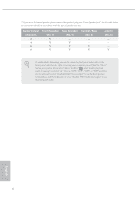
16 PCIe lanes) PCIE1 PCIE2 PCIE3 Single Graphics Card x16 N/A N/A Two Graphics Cards in CrossFireXTM or SLITM Mode x8 x8 N/A X299M Extreme4 For a better thermal environment, please connect a chassis fan to the motherboard's chassis fan connector (CHA_FAN1, CHA_FAN2 or CHA_FAN3) when using - ASRock X299M Extreme4 | Quick Installation Guide - Page 22
the pins on CLRMOS1 for 5 seconds. However, please do not clear the CMOS right after you update the BIOS. If you need to clear the CMOS when you just finish updating the BIOS, you must boot up the system first, and then shut it down before you do the clear-CMOS action - ASRock X299M Extreme4 | Quick Installation Guide - Page 23
X299M Extreme4 2.6 Onboard Headers and Connectors Onboard headers and connectors are NOT jumpers. Do NOT place jumper caps over these headers and connectors. Placing jumper caps over - ASRock X299M Extreme4 | Quick Installation Guide - Page 24
DUMMY DUMMY +5V 1 PLED+ PLED+ PLED- Please connect the chassis power LED and the chassis speaker to this header. These eight SATA3 connectors support SATA data cables for internal storage devices with up to 6.0 Gb/s data transfer rate. * If M2_1 is occupied by a SATA-type M.2 device, SATA3_0 - ASRock X299M Extreme4 | Quick Installation Guide - Page 25
for connecting audio devices to the front audio panel. 1. High Definition Audio supports Jack Sensing, but the panel wire on the chassis must support HDA to function correctly. Please follow the instructions in our manual and chassis manual to install your system. 2. If you use an AC'97 audio panel - ASRock X299M Extreme4 | Quick Installation Guide - Page 26
No. 26) 1 PCICLK FRAME PCIRST# LAD3 +3V LAD0 +3VSB GND GND SMB_CLK_MAIN SMB_DATA_MAIN LAD2 LAD1 GND S_PWRDWN# SERIRQ# GND This connector supports Trusted Platform Module (TPM) system, which can securely store keys, digital certificates, passwords, and data. A TPM system also helps enhance network - ASRock X299M Extreme4 | Quick Installation Guide - Page 27
X299M Extreme4 RGB LED Headers (4-pin RGB_LED1) (see p.1, No. 24) (4-pin RGB_LED2) (see p.1, No. 6) Performance Mode / ; otherwise, the cable may be damaged. *Please refer to page 38 for for further instructions on these two headers. Please connect the OC switch and OC LED indicator on the chassis - ASRock X299M Extreme4 | Quick Installation Guide - Page 28
operation: SKU HW key required Key features Pass-thru Not needed • Pass-thru only (no RAID) • LED Management • Hot Plug Support • RAID 0 support for Intel Fultondale NVMe SSDs Standard VROCSTANMOD • Pass-thru SKU features • RAID 0, 1, 10 Premium ISS VROCPREMMOD • Standard SKU features • RAID - ASRock X299M Extreme4 | Quick Installation Guide - Page 29
X299M Extreme4 2.7 Smart Switch The motherboard has a smart switch: Clear CMOS Button, allowing users to clear the CMOS values. Clear CMOS Button (CLRCBTN) (see p.3, No. 15) Clear - ASRock X299M Extreme4 | Quick Installation Guide - Page 30
2.8 M.2_SSD (NGFF) Module Installation Guide (M2_1) The M.2, also known as the Next Generation Form Factor (NGFF), is a small size and versatile card edge connector that aims to replace mPCIe and mSATA. The Ultra M.2 Sockets (M2_1) support SATA3 6.0 Gb/s module and M.2 PCI Express module up to Gen3 - ASRock X299M Extreme4 | Quick Installation Guide - Page 31
E D C B A A X299M Extreme4 Step 3 Move the standoff based on the module type and length. The standoff is placed at the nut location D by default. Skip Step 3 and 4 and - ASRock X299M Extreme4 | Quick Installation Guide - Page 32
Step 6 Tighten the screw with a screwdriver to secure the module into place. Please do not overtighten the screw as this might damage the module. A 30 English - ASRock X299M Extreme4 | Quick Installation Guide - Page 33
X299M Extreme4 M.2_SSD (NGFF) Module Support List Vendor ADATA ADATA ADATA ADATA ADATA ADATA ADATA Crucial Crucial Intel Intel Intel Kingston Kingston OCZ Plextor Plextor Plextor Plextor Plextor Plextor Samsung Samsung - ASRock X299M Extreme4 | Quick Installation Guide - Page 34
WD SATA3 WDS100T1B0B-00AS40 WD SATA3 WDS240G1G0B-00RC30 WD PCIe3 x4 WDS256G1X0C-00ENX0 (NVME) WD PCIe3 x4 WDS512G1X0C-00ENX0 (NVME) For the latest updates of M.2_SSD (NFGG) module support list, please visit our website for details: http://www.asrock.com English 32 - ASRock X299M Extreme4 | Quick Installation Guide - Page 35
X299M Extreme4 2.9 M.2_SSD (NGFF) Module Installation Guide (M2_2) The M.2, also known as the Next Generation Form Factor (NGFF), is a small size and versatile card edge connector that aims to replace mPCIe and mSATA. The Ultra M.2 Sockets (M2_2) support SATA3 6.0 Gb/s module and M.2 PCI Express - ASRock X299M Extreme4 | Quick Installation Guide - Page 36
A A 20o Step 3 Move the standoff based on the module type and length. The standoff is placed at the nut location D by default. Skip Step 3 and 4 and go straight to Step 5 if you are going to use the default nut. Otherwise, release the standoff by hand. Step 4 Peel off the yellow protective film - ASRock X299M Extreme4 | Quick Installation Guide - Page 37
X299M Extreme4 Step 6 Tighten the screw with a screwdriver to secure the module into place. Please do not overtighten the screw as this might damage the module. A 35 English - ASRock X299M Extreme4 | Quick Installation Guide - Page 38
M.2_SSD (NGFF) Module Support List Vendor ADATA ADATA ADATA ADATA ADATA ADATA ADATA ADATA ADATA Apacer Crucial Crucial Corsair Ezlink Intel Intel Intel Intel Intel Kingston Kingston Kingston Kingston - ASRock X299M Extreme4 | Quick Installation Guide - Page 39
X299M Extreme4 Samsung Samsung Samsung Samsung SanDisk SanDisk SanDisk SanDisk SanDisk Team Team Team Team Transcend Transcend (NVME) WDS512G1X0C-00ENX0 (NVME) For the latest updates of M.2_SSD (NFGG) module support list, please visit our website for details: http://www.asrock.com English 37 - ASRock X299M Extreme4 | Quick Installation Guide - Page 40
2.10 ASRock RGB LED ASRock RGB LED is a lighting control utility specifically designed for unique individuals that the RGB LED strips do not come with the package. 2. The RGB LED header supports standard 5050 RGB LED strip (12V/G/R/B), with a maximum power rating of 3A (12V) and length within 2 meters - ASRock X299M Extreme4 | Quick Installation Guide - Page 41
X299M Extreme4 ASRock RGB LED Utility Now you can adjust the RGB LED color through the ASRock RGB LED utility. Download this utility from the ASRock Live Update & APP Shop and start coloring your PC style your way! Drag the tab to customize your preference. Toggle on/off the RGB LED - ASRock X299M Extreme4 | Quick Installation Guide - Page 42
-Karten und Prozessoren auf der ASRock-Webseite: ASRock-Webseite http://www.asrock.com. 1.1 Lieferumfang • ASRock X299M Extreme4-Motherboard (Micro-ATX-Formfaktor) • ASRock X299M Extreme4-Schnellinstallationsanleitung • ASRock X299M Extreme4-Support-CD • 1 x E/A-Blendenabschirmung • 2 x Serial-ATA - ASRock X299M Extreme4 | Quick Installation Guide - Page 43
X299M Extreme4 1.2 Technische Daten Plattform • Micro-ATX-Formfaktor Prozessor • Unterstützt Prozessoren der Intel®-CoreTM-X-Series-Familie für den LGA-2066 finden Sie in der Speicherkompatibilitätsliste auf der ASRock-Webseite. (http://www.asrock.com/) • Systemspeicher, max. Kapazität: 64GB - ASRock X299M Extreme4 | Quick Installation Guide - Page 44
Audio LAN • Unterstützt AMD Quad CrossFireXTM und CrossFireXTM • Unterstützt NVIDIA® Quad SLITM und SLITM • 15-μ-Goldkontakt in VGA-PCIe-Steckplatz (PCIE1 und PCIE2) • 7.1-Kanal-HD-Audio mit Inhaltsschutz (Realtek ALC1220Audiocodec) • Erstklassige Blu-ray-Audiounterstützung • Unterstützt Ü - ASRock X299M Extreme4 | Quick Installation Guide - Page 45
X299M Extreme4 Speicher Anschluss • 1 x CMOS-löschen-Taste • HD-Audioanschlüsse: Hintere Lautsprecher / Zentral / ** Unterstützt Intel® OptaneTM-Technologie ** Unterstützt NVMe-SSD als Bootplatte ** Unterstützt ASRock U.2-Kit • 1 x Virtual RAID an der CPU-Stiftleiste • 1 x TPM-Stiftleiste • 1 - ASRock X299M Extreme4 | Quick Installation Guide - Page 46
- Ports) (unterstützt Schutz gegen elektrostatische Entladung) • 1 x Leistungsmodus / einfache Übertaktungsstiftleiste BIOSFunktion • AMI-UEFI-Legal-BIOS mit Unterstützung mehrsprachiger grafischer Benutzerschnittstellen • ACPI 6.1-konforme Aufweckereignisse • SMBIOS 3.0-Unterstützung • CPU, DRAM - ASRock X299M Extreme4 | Quick Installation Guide - Page 47
X299M Extreme4 * Detaillierte Produktinformationen finden Sie auf unserer Webseite: http://www.asrock.com Bitte beachten Sie, dass mit einer Übertaktung, zu der die Anpassung von BIOS-Einstellungen, die Anwendung der Untied Overclocking Technology oder die Nutzung von Übertaktungswerkzeugen von - ASRock X299M Extreme4 | Quick Installation Guide - Page 48
Kontakte an CLRMOS1 5 Sekunden lang mit einer Jumper-Kappe kurz. Löschen Sie den CMOS jedoch nicht direkt nach der BIOS-Aktualisierung. Falls Sie den CMOS direkt nach Abschluss der BIOS-Aktualisierung löschen müssen, starten Sie das System zunächst; fahren Sie es dann vor der CMOS-Löschung herunter - ASRock X299M Extreme4 | Quick Installation Guide - Page 49
X299M Extreme4 1.4 Integrierte Stiftleisten und Anschlüsse Integrierte Stiftleisten und Anschlüsse sind KEINE Jumper. Bringen Sie KEINE Jumper-Kappen an diesen Stiftleisten und Anschlüssen an. - ASRock X299M Extreme4 | Quick Installation Guide - Page 50
SATA3_6 SATA3_4 SATA3_2 SATA3_0 SATA3_7 SATA3_5 SATA3_3 SATA3_1 Betrieb-LED- und Lautsprecher-Stiftleiste (7-polig, SPK_PLED1) (siehe S. 1, Nr. 16) Serial-ATA-III-Anschlüsse (SATA3_0_1: siehe S. 1, Nr. 11) (SATA3_2_3: siehe S. 1, Nr. 13) (SATA3_4_5: siehe S. 1, Nr. 14) (SATA3_6_7: siehe S. 1, Nr. - ASRock X299M Extreme4 | Quick Installation Guide - Page 51
X299M Extreme4 Audiostiftleisten (Frontblende) (9-polig, HD_AUDIO1) (siehe S. 1, Nr. 28) (9-polig, HD_AUDIO_RA1) (siehe S. 1, Nr. 27) GND PRESENCE# MIC_RET OUT_RET 1 OUT2_L J_SENSE OUT2_R MIC2_R MIC2_L Diese Stiftleiste dient dem - ASRock X299M Extreme4 | Quick Installation Guide - Page 52
Optionale-CPU-/ Wasserpumpen- FAN_SPEED Dieses Motherboard bietet einen FAN_VOLTAGE_CONTROL GND FAN_SPEED_CONTROL 4-poligen Wasserkühlung-CPU- Lüfteranschluss Lüfteranschluss. Falls Sie einen (4-polig, CPU_OPT/WP) 3-poligen CPU-Wasserkühler- (siehe S. 1, Nr. 7) lüfter anschließen möchten, - ASRock X299M Extreme4 | Quick Installation Guide - Page 53
X299M Extreme4 RGB-LED-Stiftleisten (4-polig, RGB_LED1) (siehe S. 1, Nr. 24) (4-polig, RGB_LED2) (siehe S. 1, Nr. 6) 1 12V G R B Diese beiden RGB-Stiftleisten dienen dem Anschließen eines RGB-LED-Erweiterungskabels, - ASRock X299M Extreme4 | Quick Installation Guide - Page 54
Virtual RAID an der CPUStiftleiste (4-polig VROC1) (siehe S. 1, Nr. 23) 1 GND +3VSB GND VROC RAID KEY Dieser Anschluss unterstützt Intel® Virtual RAID an CPU und NVME/AHCI RAID an CPU PCIE. Mit der Einführung des Intel-VROC-Produktes gibt es drei Betriebsmodi: SKU Pass-thru HW-Taste - ASRock X299M Extreme4 | Quick Installation Guide - Page 55
X299M Extreme4 1.5 Intelligente Schalter Das Motherboard hat einen intelligenten Schalter: CMOS-leeren-Taste, mit der Nutzer die CMOS-Werte löschen können. CMOS-löschen-Taste (CLRCBTN) (siehe S. 3, Nr. - ASRock X299M Extreme4 | Quick Installation Guide - Page 56
le site Internet de ASRock. Site Internet ASRock http://www.asrock.com. 1.1 Contenu de l'emballage • Carte mère ASRock X299M Extreme4 (facteur de forme Micro ATX) • Guide d'installation rapide ASRock X299M Extreme4 • CD d'assistance ASRock X299M Extreme4 • 1 x panneau de protection E/S • 2 x câbles - ASRock X299M Extreme4 | Quick Installation Guide - Page 57
X299M Extreme4 1.2 Spécifications Plateforme • Facteur de forme Micro ATX Processeur • Prend en charge la famille de processeurs Intel® CoreTM X-Series pour le socket LGA 2066 des mémoires sur le site Web d'ASRock pour de plus amples informations. (http://www. asrock.com/) • Capacité max. de la - ASRock X299M Extreme4 | Quick Installation Guide - Page 58
• Prend en charge AMD Quad CrossFireXTM et CrossFireXTM • Prend en charge NVIDIA® Quad SLITM et SLITM • Contact doré 15μ dans fente VGA PCIe (PCIE1 et PCIE2) Audio • Audio 7.1 CH HD avec protection du contenu (codec audio Realtek ALC1220) • Compatible audio Blu-ray Premium • Prend en charge la - ASRock X299M Extreme4 | Quick Installation Guide - Page 59
X299M Extreme4 Stockage Connecteur • 1 x bouton Clear CMOS • Connecteurs jack audio HD : Haut-parleur arrière OptaneTM Technology ** Prend en charge les SSD NVMe comme disques de démarrage ** Prend en charge le kit ASRock U.2 • 1 x Virtual RAID sur embase de processeur • 1 x embase TPM • 1 x prise - ASRock X299M Extreme4 | Quick Installation Guide - Page 60
USB 3.1 Gen1 pris en charge) (Protection contre les décharges électrostatiques) • 1 x Embase mode Performances / OC facile Caractéristiques du BIOS • BIOS UEFI AMI avec prise en charge d'interface graphique multilingue • Compatible ACPI 6.1 Wake Up Events • Compatible SMBIOS 3.0 • Réglage de la - ASRock X299M Extreme4 | Quick Installation Guide - Page 61
X299M Extreme4 * pour des informations détaillées de nos produits, veuillez visiter notre site : http://www.asrock.com Il est important de signaler que l'overclocking présente certains risques, incluant des modifications du BIOS, l'application d'une technologie d'overclocking déliée et l'utilisation - ASRock X299M Extreme4 | Quick Installation Guide - Page 62
broches sur CLRMOS1 pendant 5 secondes. Toutefois, n'effacez pas la CMOS immédiatement après avoir mis à jour le BIOS. Si vous avez besoin d'effacer les données CMOS après une mise à jour du BIOS, vous devez tout d'abord redémarrer le système, puis l'éteindre avant de procéder à l'effacement de la - ASRock X299M Extreme4 | Quick Installation Guide - Page 63
X299M Extreme4 1.4 Embases et connecteurs de la carte mère Les embases et connecteurs situés sur la carte NE SONT PAS des cavaliers. Ne placez JAMAIS de capuchons - ASRock X299M Extreme4 | Quick Installation Guide - Page 64
Prise DEL d'alimentation et haut-parleur (SPK_PDEL1 à 7 broches) (voir p.1, No. 16) SPEAKER DUMMY DUMMY +5V 1 PLED+ PLED+ PLED- Veuillez brancher la DEL d'alimentation du châssis et le haut-parleur du châssis sur ce connecteur. Connecteurs Serial ATA3 (SATA3_0_1: voir p.1, No. 11) (SATA3_2_3: - ASRock X299M Extreme4 | Quick Installation Guide - Page 65
X299M Extreme4 Embases audio du panneau frontal (HD_AUDIO1 à 9 broches) (voir p.1, No. 28) (HD_AUDIO_RA1 du châssis doit être compatible avec la HDA pour fonctionner correctement. Veuillez suivre les instructions figurant dans notre manuel et dans le manuel du châssis pour installer votre système. - ASRock X299M Extreme4 | Quick Installation Guide - Page 66
Connecteur du ventilateur de Cette carte mère est dotée CPU optionnel/pompe à eau FAN_SPEED d'un connecteur pour FAN_VOLTAGE_CONTROL (CPU_OPT/WP à 4 broches) GND FAN_SPEED_CONTROL ventilateur de processeur à (voir p.1, No. 7) refroidissement par eau à 4 broches. Si vous envisagez de - ASRock X299M Extreme4 | Quick Installation Guide - Page 67
X299M Extreme4 Embase DEL RVB (RGB_DEL1 à 4 broches) (voir p.1, No. 24) (RGB_DEL2 à 4 broches) (voir p.1, No. 6) Embase , le câble peut être endommagé. *Veuillez consulter la page 38 pour des instructions supplémentaires sur ces deux embases. Veuillez connecter le commutateur OC et l'indicateur DEL - ASRock X299M Extreme4 | Quick Installation Guide - Page 68
Virtual RAID sur embase de processeur (VROC1 à 4 broches) (voir p.1, No. 23) 1 GND +3VSB GND VROC RAID KEY Ce connecteur prend en charge Intel® Virtual RAID sur processeur et NVME/AHCI RAID sur processeur PCIE. Avec le lancement du produit Intel VROC,il existe trois modes de fonctionnement : SKU - ASRock X299M Extreme4 | Quick Installation Guide - Page 69
X299M Extreme4 1.5 Bouton intelligent La carte mère dispose d'un commutateur intelligent : Bouton Effacer CMOS, permettant aux utilisateurs d'effacer les valeurs CMOS. Bouton Clear CMOS (CLRCBTN) (voir p.3, No. - ASRock X299M Extreme4 | Quick Installation Guide - Page 70
anche sul sito Web di ASRock. Sito Web di ASRock http://www.asrock.com. 1.1 Contenuto della confezione • Scheda madre ASRock X299M Extreme4 (Form Factor Micro ATX) • Guida all'installazione rapida di ASRock X299M Extreme4 • CD di supporto ASRock X299M Extreme4 • 1 x mascherina metallica posteriore - ASRock X299M Extreme4 | Quick Installation Guide - Page 71
X299M Extreme4 1.2 Specifiche Piattaforma • Fattore di forma Micro ATX CPU • Supporta la famiglia di processori Intel® CoreTM serie X per il socket LGA 2066 riferimento all'elenco dei supporti di memoria sul sito di ASRock. (http://www.asrock.com/) • Capacità max. della memoria di sistema: - ASRock X299M Extreme4 | Quick Installation Guide - Page 72
• Supporta AMD Quad CrossFireXTM e CrossFireXTM • Supporta NVIDIA® Quad SLITMe SLITM • Contatti d'oro 15μ nell'alloggio VGA PCIe (PCIE1 e PCIE2) Audio • Audio HD a 7.1 canali con Content Protection (codec audio Realtek ALC1220) • Supporto audio Blu-ray Premium • Supporta protezione da - ASRock X299M Extreme4 | Quick Installation Guide - Page 73
X299M Extreme4 • 1 x pulsante per azzerare la CMOS • Connettori audio HD: altoparlante posteriore/centrale/basso Supporta la tecnologia Intel® OptaneTM ** Supporto di SSD NVMe come disco d'avvio ** Supporta kit ASRock U.2 Connettore • 1 x RAID virtuale su connettore CPU • 1 x connettore TPM • 1 - ASRock X299M Extreme4 | Quick Installation Guide - Page 74
USB 3.1 Gen1) (supporto protezione da scariche elettrostatiche) • 1 Basetta Modalità prestazioni / Overclocking (OC) facile Funzionalità BIOS • AMI UEFI Legal BIOS con interfaccia di supporto multilingue • Eventi di riattivazione conformi a ACPI 6.1 • Supporto di SMBIOS 3.0 • Regolazione multipla - ASRock X299M Extreme4 | Quick Installation Guide - Page 75
X299M Extreme4 * Per informazioni dettagliate sul prodotto, visitare il nostro sito Web: http://www.asrock.com Prestare attenzione al potenziale rischio previsto nella pratica di overclocking, inclusa la regolazione delle impostazioni nel BIOS, l'applicazione di tecnologia di Untied Overclocking o - ASRock X299M Extreme4 | Quick Installation Guide - Page 76
per cortocircuitare i di CLRMOS1 per 5 secondi. Tuttavia, non azzerare la CMOS subito dopo aver aggiornato il BIOS. Se è necessario azzerare la CMOS dopo l'aggiornamento del BIOS, è necessario riavviare prima il sistema e in seguito spegnerlo prima di eseguire l'operazione di azzeramento della CMOS - ASRock X299M Extreme4 | Quick Installation Guide - Page 77
X299M Extreme4 1.4 Header e connettori su scheda Gli header e i connettori sulla scheda NON sono jumper. NON posizionare cappucci del jumper su questi header e connettori. Il posizionamento di cappucci - ASRock X299M Extreme4 | Quick Installation Guide - Page 78
Connettore LED alimentazione e altoparlante (SPK_PLED1 a 7 pin) (vedere pag. 1, n. 16) SPEAKER DUMMY DUMMY +5V 1 PLED+ PLED+ PLED- Collegare i LED alimentazione e l'altoparlante a questo connettore. Connettori Serial ATA3 (SATA3_0_1: vedere pag. 1, n. 11) (SATA3_2_3: vedere pag. 1, n. 13) ( - ASRock X299M Extreme4 | Quick Installation Guide - Page 79
X299M Extreme4 Header audio pannello anteriore (AUDIO1_HD a 9 pin) (vedere pag. 1, n. 28) (RA1_AUDIO_HD a 9 pin) ( deve supportare HDA per funzionare correttamente. Seguire le istruzioni presenti nel nostro manuale e nel manuale dello chassis per installare il sistema. 2. Se si utilizza un pannello - ASRock X299M Extreme4 | Quick Installation Guide - Page 80
Connettore ventola CPU FAN_SPEED Questa scheda madre è FAN_VOLTAGE_CONTROL optional / pompa dell'acqua GND FAN_SPEED_CONTROL dotata di un connettore per (CPU_OPT/WP a 4 pin) la ventola della CPU con (vedere pag. 1, n. 7) raffreddamento ad acqua a 4 pin. Se si decide di collegare una - ASRock X299M Extreme4 | Quick Installation Guide - Page 81
X299M Extreme4 Collettore LED RGB (RGB_LED1 a 4 pin) (vedere pag. 1, n. 24) (RGB_LED2 a 4 pin) (vedere pag. 1, n. 6) Basetta Modalità prestazioni / Overclocking (OC) facile (PM_EO a 4 pin) (vedere pag. 1, n. 25) 1 12V G R B 1 Button+ - ASRock X299M Extreme4 | Quick Installation Guide - Page 82
RAID virtuale su connettore CPU (VROC1 a 4 pin) (vedere pag. 1, n. 23) 1 GND +3VSB GND VROC RAID KEY Questo connettore supporta RAID virtuale Intel® su CPU e RAID NVME/AHCI su PCIE CPU. Con l'introduzione del prodotto Intel VROC, ci sono tre modalità di funzionamento: SKU Passthrough Tasto - ASRock X299M Extreme4 | Quick Installation Guide - Page 83
X299M Extreme4 1.5 Interruttore automatico La scheda madre dispone di un interruttore intuitivo: Tasto Clear CMOS che permette di cancellare i valori CMOS. Tasto Cancella CMOS (CLRCBTN) (vedere pag. 3, n. - ASRock X299M Extreme4 | Quick Installation Guide - Page 84
ASRock X299M Extreme4, una placa base fiable fabricada según el rigurosísimo control de calidad de ASRock. Ofrece un rendimiento excelente con un diseño resistente de acuerdo con el compromiso de calidad y resistencia de ASRock. Ya que las especificaciones de la placa base y el software de la BIOS - ASRock X299M Extreme4 | Quick Installation Guide - Page 85
X299M Extreme4 1.2 Especificaciones Plataforma • Factor de forma Micro ATX CPU • Admite la familia de procesadores Intel® CoreTM serie X para el zócalo LGA 2066 la lista de memorias compatibles en el sitio web de ASRock. (http://www.asrock.com/) • Capacidad máxima de memoria del sistema: 64GB - ASRock X299M Extreme4 | Quick Installation Guide - Page 86
• Compatible con AMD Quad CrossFireXTM y CrossFireXTM • Compatible con NVIDIA® Quad SLITM y SLITM • Contacto 15μGold en ranura VGA PCIe (PCIE1 y PCIE2) Audio • 7.1 Audio CH HD con Protección de contenido (Realtek ALC1220 Audio Codec) • Compatible con audio Blu-ray Premium • Admite protección - ASRock X299M Extreme4 | Quick Installation Guide - Page 87
X299M Extreme4 Almacenamiento Conector • 1 x botón de borrado CMOS • Conector de audio HD: Altavoz trasero / Central Intel® ** Admite unidad de estado sólido de NVMe como disco de arranque ** Admite el kit U.2 de ASRock • 1 x RAID virtual en base de conexiones de CPU • 1 x Conector TPM • 1 x LED - ASRock X299M Extreme4 | Quick Installation Guide - Page 88
USB 3.1 Gen1 (admite 2 puertos USB 3.1 Gen1). Admite protección contra descargas electrostáticas. • 1 x Modo de rendimiento / Base de conexiones OC sencilla • BIOS legal UEFI AMI compatible con interfaz gráfica de usuario multilingüe • Eventos de reactivación compatibles con ACPI 6.1 • Admite SMBIOS - ASRock X299M Extreme4 | Quick Installation Guide - Page 89
X299M Extreme4 * Para obtener información detallada del producto, visite nuestro sitio Web: http://www.asrock.com Tenga en cuenta que hay un cierto riesgo implícito en las operaciones de overclocking, incluido el ajuste de la BIOS, aplicando la tecnología de overclocking liberada o utilizando las - ASRock X299M Extreme4 | Quick Installation Guide - Page 90
en el CLRMOS1 durante 5 segundos. Sin embargo, no borre el CMOS justo después de que haya actualizado la BIOS. Si necesita borrar el CMOS cuando acabe de actualizar la BIOS, deberá arrancar el sistema primero y, a continuación, deberá apagarlo antes de que realice el borrado del CMOS. Tenga en - ASRock X299M Extreme4 | Quick Installation Guide - Page 91
X299M Extreme4 1.4 Conectores y cabezales incorporados Los cabezales y conectores incorporados NO son puentes. NO coloque tapas de puente sobre estos cabezales y conectores. Si coloca tapas de puente sobre - ASRock X299M Extreme4 | Quick Installation Guide - Page 92
LED de alimentación y base de conexiones para la altavoz (SPK_PLED1 de 7 contactos) (consulte la pág.1, Nº 16) SPEAKER DUMMY DUMMY +5V 1 PLED+ PLED+ PLED- Conecte el LED de alimentación del chasis y el altavoz del chasis a esta base de conexiones. Conectores Serie ATA3 (SATA3_0_1: consulte la - ASRock X299M Extreme4 | Quick Installation Guide - Page 93
X299M Extreme4 Cabezal de audio del panel frontal (HD_AUDIO1 de 9 contactos) (consulte la pág.1, Nº 28) con HDA para que pueda funcionar correctamente. Siga las instrucciones que se indican en nuestro manual y en el manual del chasis para instalar su sistema. 2. Si utiliza un panel de audio AC'97, - ASRock X299M Extreme4 | Quick Installation Guide - Page 94
Conector del ventilador de Esta placa base proporciona la bomba de agua/ FAN_SPEED un conector de ventilador FAN_VOLTAGE_CONTROL GND FAN_SPEED_CONTROL opcional de la CPU de CPU de refrigeración (CPU_OPT/WP de 4 por agua de 4 contactos. Si contactos) tiene pensando conectar un (consulte - ASRock X299M Extreme4 | Quick Installation Guide - Page 95
X299M Extreme4 Cabezales de LED RGB (RGB_LED1 de 4 contactos) (consulte la pág.1, Nº 24) (RGB_LED2 de 4 contactos) (consulte la pág.1, Nº 6) 1 12V G R B Modo de rendimiento / Base de conexiones OC sencilla (PM_EO - ASRock X299M Extreme4 | Quick Installation Guide - Page 96
RAID virtual en base de conexiones de CPU (VROC1 de 4 contactos) (consulte la pág.1, Nº 23) 1 GND +3VSB GND VROC RAID KEY Este conector admite RAID virtual en CPU de Intel® y RAID NVME/AHCI en CPU PCIE. Con la introducción del producto VROC de Intel, existen tres modos de funcionamiento: SKU - ASRock X299M Extreme4 | Quick Installation Guide - Page 97
X299M Extreme4 1.5 Interruptor inteligente La placa base tiene un conmutador inteligente: El botón limpiar CMOS permite a los usuarios limpiar los valores CMOS. Botón Borrar la memoria CMOS ( - ASRock X299M Extreme4 | Quick Installation Guide - Page 98
1 ASRock X299M Extreme4 ASRock ASRock BIOS ASRock ASRock VGA ASRock http://www.asrock.com. 1.1 ASRock X299M Extreme4 Micro ATX ASRock X299M Extreme4 ASRock X299M Extreme4 • 1 x 2 x Serial ATA (SATA 1 x карта ASRock SLI_HB_Bridge_1S 2 x M.2 96 - ASRock X299M Extreme4 | Quick Installation Guide - Page 99
LGA 2066. • Digi Power design 11 Intel® Turbo Boost Max 3.0 4 Intel® Turbo Boost 2.0. • Intel® X299 Память DDR4 • 4 x DDR4 DIMM DDR4 4266+(OC)*/4200(OC)/ 4133(OC)/4000(OC)/3866 (OC)/3800(OC)/3733(OC)/3600 (OC)/3200(OC)/2933 (OC)/2800 (OC)/2666/2400/2133 ECC Memory Support List ASRock - ASRock X299M Extreme4 | Quick Installation Guide - Page 100
Звук LAN • 7.1 HD Audio Realtek ALC1220) Premium Blu-ray Audio Purity SoundTM 4 Nichicon Fine Gold - 120 дБ SNR DAC NE5532 600 Ом) Direct Drive 15 DTS • Gigabit Ethernet 10/100/1000 1 x Giga PHY Intel® I219V, 1 x GigaLAN Intel® I211AT Windows® 10 RS2 - ASRock X299M Extreme4 | Quick Installation Guide - Page 101
X299M Extreme4 • 8 x SATA3 6,0 RAID (RAID 0, RAID 1, RAID 5, RAID 10 M.** • 1 x слот Ultra M.2 (M2_2 M.2 SATA3 M типа 2260/2280 6,0 M.2 PCI Express Gen3 x4 (32 Intel® OptaneTM SSD NVMe ASRock U.2 • 1 x RAID 1 x 1 x 2 x RGB- 12 В/3 36 Вт). • 1 x 4 1 А (12 Вт). • - ASRock X299M Extreme4 | Quick Installation Guide - Page 102
мкм)* • 1 x 1 x AIC Thunderbolt (5 ThunderboltTM AIC PCIe 2 x USB 2.0 (4 порта USB 2.0 1 x USB 3.1 Gen1 (2 порта USB 3.1 Gen1) (с 1 x BIOS • AMI UEFI Legal BIOS ACPI 6.1 SMBIOS 3.0 DRAM, VPPM, VTTM, PCH 1,0V, VCCIO, VCCST, VCCSA, VCCSFR, VCCPLL 12 - ASRock X299M Extreme4 | Quick Installation Guide - Page 103
X299M Extreme4 http://www.asrock.com BIOS Untied Overclocking 101 - ASRock X299M Extreme4 | Quick Installation Guide - Page 104
1.3 CMOS (CLRMOS1 1, № 12) 2 CLRMOS1 CMOS 15 CLRMOS1 на 5 CMOS BIOS CMOS BIOS CMOS CMOS CMOS CMOS CMOS. 102 - ASRock X299M Extreme4 | Quick Installation Guide - Page 105
X299M Extreme4 1.4 9 PANEL1 1, № 17) PLED+ PLEDPWRBTN# GND 1 GND RESET# GND HDLEDHDLED+ PWRBTN RESET PLED S1/S3 S4 S5 HDLED 103 - ASRock X299M Extreme4 | Quick Installation Guide - Page 106
7 SPK_PLED1 1, № 16) Serial ATA3 (SATA3_0_1 1, № 11) (SATA3_2_3 1, № 13) (SATA3_4_5 1, № 14) (SATA3_6_7 1, № 15) USB 2.0 (9 USB_5_6 1, № 20) (9 USB_7_8 1, № 19) SPEAKER DUMMY DUMMY +5V 1 PLED+ PLED+ PLED- SATA3_6 SATA3_4 SATA3_2 SATA3_0 SATA3_7 SATA3_5 SATA3_3 SATA3_1 USB_PWR - ASRock X299M Extreme4 | Quick Installation Guide - Page 107
X299M Extreme4 9 HD_AUDIO1 1, № 28) (9 HD_AUDIO_ RA1 1, № 27) GND PRESENCE# MIC_RET OUT_RET 1 OUT2_L J_SENSE OUT2_R MIC2_R MIC2_L 1 HDA 2 AC'97 A Mic_IN (MIC) к MIC2_L. B Audio_R (RIN) к OUT2_R, Audio_L (LIN) к - ASRock X299M Extreme4 | Quick Installation Guide - Page 108
FAN_SPEED 4 FAN_VOLTAGE_CONTROL GND FAN_SPEED_CONTROL 3 (4 CPU_OPT/ WP) 1, № 7) 1-3. 24 ATXPWR1 1, № 9) 12 24 1 13 24 20 ATX 1 13. 12 В (8 ATX12V1 1, № 2) (8 ATX12V2 1, № 3) 8 5 8 4 1 12 4 ATX, - ASRock X299M Extreme4 | Quick Installation Guide - Page 109
X299M Extreme4 RGB 4 RGB_LED1 1, № 24) (4 RGB_LED2 1, № 6) 4 PM_EO 1, № 25) 1 12V G R B 1 Button+ ButtonOCLED+ OCLED - RGB RGB RGB 38. 107 - ASRock X299M Extreme4 | Quick Installation Guide - Page 110
RAID 4 VROC1 1, № 23) 1 GND +3VSB GND VROC RAID KEY RAID Intel RAID NVME/ AHCI PCIE ЦП. Intel VROC VROCSTANMOD RAID RAID 0 для SSD- Intel Fultondale NVMe RAID 0, 1, 10 ISS VROCPREMMOD VROCISSDMOD RAID 5 RAID 5 Write Hole Intel VROC Intel - ASRock X299M Extreme4 | Quick Installation Guide - Page 111
X299M Extreme4 1.5 CMOS CMOS CMOS (CLRCBTN 3, № 15) CMOS CMOS. 109 - ASRock X299M Extreme4 | Quick Installation Guide - Page 112
mais recentes suportadas no site da ASRock. Site da ASRock http://www.asrock.com. 1.1 Conteúdo da embalagem • Placa Mãe ASRock X299M Extreme4 (Micro ATX Form Factor) • Guia de Instalação Rápida da ASRock X299M Extreme4 • CD de Suporte da ASRock X299M Extreme4 • 1 x Painel de E/S • 2 x Cabos de dados - ASRock X299M Extreme4 | Quick Installation Guide - Page 113
X299M Extreme4 1.2 Especificações Plataforma • Micro ATX Form Factor CPU • Suporta Processadores da família Intel® CoreTM série X para o Soquete LGA 2066 Lista de Suporte de Memória no site da ASRock para obter mais informação. (http://www.asrock.com/) • Capacidade máxima da memória do sistema - ASRock X299M Extreme4 | Quick Installation Guide - Page 114
• Suporta AMD Quad CrossFireXTM e CrossFireXTM • Suporta Quad SLITM e SLITM da NVIDIA® • Contato em Ouro 15μ no Slot PCIe VGA (PCIE1 e PCIE2) Áudio • Áudio HD de 7.1 canais com proteção de conteúdo (Codec de áudio Realtek ALC1220) • Suporte áudio Blu-ray superior • Suporta Proteção de Sobretensão - ASRock X299M Extreme4 | Quick Installation Guide - Page 115
X299M Extreme4 Português Armazenamento Conector • 1 x botão de limpeza CMOS • Fichas de áudio HD: (32 Gb/s) ** ** Suporta Tecnologia Intel® OptaneTM ** Suporta NVMe SSD como discos de inicialização ** Suporta Kit ASRock U.2 • 1 x RAID Virtual no cabeçote da CPU • 1 x Plataforma TPM • 1 x LED de - ASRock X299M Extreme4 | Quick Installation Guide - Page 116
ESD) • 1 x Plataforma USB 3.1 Gen1 (Suporta 2 portas USB 3.1 Gen1) (Suporta Proteção ESD) • 1 x Modo de Desempenho/Título OC Fácil • AMI Legal UEFI BIOS com suporte multilingue GUI • ACPI 6.1 compatível com eventos de despertar • Suporte SMBIOS 3.0 • Multi ajuste de tensão de CPU, DRAM, VPPM, VTTM - ASRock X299M Extreme4 | Quick Installation Guide - Page 117
X299M Extreme4 * Para obter informações detalhadas sobre o produto, por favor, visite o nosso site: http://www.asrock.com Por favor, observe que existe um certo risco envolvendo overclocking, incluindo o ajuste das definições na BIOS, a aplicação de tecnologia Untied Overclocking ou a utilização de - ASRock X299M Extreme4 | Quick Installation Guide - Page 118
dos pinos no CLRMOS1 por 5 segundos. No entanto, não apague o CMOS logo após ter realizado a atualização da BIOS. Se você precisar apagar o CMOS logo após ter terminado uma atualização da BIOS, deverá primeiro iniciar o sistema e voltar a encerrá-lo antes de apagar o CMOS. Por favor, observe que - ASRock X299M Extreme4 | Quick Installation Guide - Page 119
X299M Extreme4 1.4 Suportes e conectores onboard Os conectores e suportes onboard NÃO são jumpers. NÃO coloque tampas de jumpers sobre estes terminais e conectores Colocar tampas de jumpers sobre os terminais e conectores irá - ASRock X299M Extreme4 | Quick Installation Guide - Page 120
LED de alimentação e Cabeçote de Autofalante (SPK_PLED1 de 7 pinos) (ver p.1, N.º 16) SPEAKER DUMMY DUMMY +5V 1 PLED+ PLED+ PLED- Conecte o LED de alimentação do chassi e o autofalante do chassi a este cabeçote. Conectores série ATA3 (SATA3_0_1: ver p.1, N.º 11) (SATA3_2_3: ver pág.1 No. 13) ( - ASRock X299M Extreme4 | Quick Installation Guide - Page 121
X299M Extreme4 Português Suporte de áudio do painel frontal (HD_AUDIO1 de 9 pinos) (ver p.1, N.º 28) no chassi deverá suportar HDA para funcionar corretamente. Por favor, siga as instruções no nosso manual e no manual do chassi para instalar o seu sistema. 2. Se utilizar um painel de áudio AC'97, - ASRock X299M Extreme4 | Quick Installation Guide - Page 122
Conector da ventoinha FAN_SPEED Esta placa mãe inclui um conec- FAN_VOLTAGE_CONTROL de bomba de água/CPU GND FAN_SPEED_CONTROL tor de ventilador da CPU de opcional refrigeração a água de 4 pinos. (CPU_OPT/WP de pinos) Se você pretende conectar um (ver p.1, N.º 7) ventilador de refrigera - ASRock X299M Extreme4 | Quick Installation Guide - Page 123
X299M Extreme4 Cabeçotes de LED RGB (RGB_LED1 de 4 pinos) (ver p.1, N.º 24) (RGB_LED2 de 4 pinos) (ver p.1, N.º 6) Modo de Desempenho/ Título OC Fácil (PM_EO de 4 pinos) (ver p.1, N.º 25) 1 - ASRock X299M Extreme4 | Quick Installation Guide - Page 124
RAID Virtual no cabeçote da CPU (VROC1 de 4 pinos) (ver p.1, N.º 23) 1 GND +3VSB GND VROC RAID KEY Este conector suporta Intel® Virtual RAID na CPU e RAID NVME/AHCI na CPU PCIE. Com a introdução do produto Intel VROC, existem três modos de operação: SKU Requer uma chave HW Pasagem Não necessário - ASRock X299M Extreme4 | Quick Installation Guide - Page 125
X299M Extreme4 1.5 Chave inteligente A placa mãe em uma chave inteligente: Apagar o Botão CMOS, permitindo que os usuários apaguem os valores CMOS. Botão Limpar CMOS (CLRCBTN) (ver p.3, N.º 15) O - ASRock X299M Extreme4 | Quick Installation Guide - Page 126
kalite kontrol süreçlerinden geçmiş olan ASRock X299M Extreme4 anakartını satın aldığınız için teşekkür ederiz. Sağlam tasarımı ile ASRock'ın kalite ve dayanıklılık taahhüdüne uygun şekilde mükemmel performans sağlar. Ana kart özellikleri ve BIOS yazılımı güncellenebileceğinden, bu belgenin içeri - ASRock X299M Extreme4 | Quick Installation Guide - Page 127
X299M Extreme4 1.2 Özellikler Platform İşlemci Yonga kümesi Bellek Genişletme Yuvası • Micro ATX Form Faktörü • LGA 2066 Yuva için Intel® CoreTM sterebilir. * Ayrıntılı bilgi için ASRock'ın web sitesindeki Bellek Desteği Listesine bakın. (http://www.asrock.com/) • En fazla sistem belleği kapasitesi - ASRock X299M Extreme4 | Quick Installation Guide - Page 128
Türkçe Ses LAN Arka Panel G/Ç • AMD Quad CrossFireXTM ve CrossFireXTM desteğine sahiptir • NVIDIA® Quad SLITM ve SLITM birimlerini destekler • VGA PCIe Yuvasında (PCIE1 ve PCIE2) 15μ Altın Temas • İçerik Koruma özelliğine sahip 7.1 kanal HD Ses (Realtek ALC1220 Ses Kodlayıcı-Kod Çözücü) • Üstün - ASRock X299M Extreme4 | Quick Installation Guide - Page 129
X299M Extreme4 Türkçe Depolama Bağlayıcı • 1 tane CMOS Temizleme Düğmesi • HD Ses Girişleri/Çıkışlar ülünü destekler** ** Intel® OptaneTM Teknolojisini destekler ** Önyükleme diskleri olarak NVMe SSD destekler ** ASRock U.2 Takımını destekler • İşlemci Bağlantısında 1 tane Sanal RAID • 1 tane TPM - ASRock X299M Extreme4 | Quick Installation Guide - Page 130
Gen1 bağlantı noktasını destekler) (ESD Korumasını destekler) • 1 tane Performans Modu / Kolay OC Bağlantısı Türkçe BIOS Özelliği • Çok dilli kullanıcı arayüzü desteğiyle AMI UEFI Legal BIOS • ACPI 6.1 Uyumlu uyandırma olayları • SMBIOS 3.0 Desteği • CPU, DRAM, VPPM, VTTM, PCH 1,0V, VCCIO, VCCST - ASRock X299M Extreme4 | Quick Installation Guide - Page 131
Türkçe X299M Extreme4 * Detaylı ürün bilgisi için lütfen web sitemizi ziyaret edin: http://www.asrock.com Lütfen, BIOS ayarlarını düzenleme, Bağımsız Hız Aşırtma Teknolojisinin uygulanması veya üçüncü taraf hız aşırtma araçlarının kullanılması da dâhil olmak üzere tüm hız aşırtma işlemlerinin - ASRock X299M Extreme4 | Quick Installation Guide - Page 132
, CLRMOS1 üzerindeki pimlere 5 saniye boyunca kısa devre yaptırmak için bir atlama kapağı kullanın. Ancak, CMOS'u lütfen BIOS'u güncelledikten hemen sonra temizlemeyin. BIOS'u güncelledikten hemen sonra CMOS'u temizlemeniz gerekirse, önce sistemi başlatın ve ardından CMOS temizleme işlemi öncesinde - ASRock X299M Extreme4 | Quick Installation Guide - Page 133
X299M Extreme4 1.4 Yerleşik Bağlantılar ve Bağlayıcılar Yerleşik bağlantılar ve bağlayıcılar bağlantı teli değildir. Bağlantı - ASRock X299M Extreme4 | Quick Installation Guide - Page 134
Türkçe Güç LED'i ve Hoparlör Bağlantısı (7 pimli SPK_PLED1) (bk. s.1, No. 16) Seri ATA3 Bağlayıcıları (SATA3_0_1: bk. s.1, No. 11) (SATA3_2_3: bkz. s.1, No. 13) (SATA3_4_5: bk. s.1, No. 14) (SATA3_6_7: bk. s.1, No. 15) USB 2.0 Bağlantıları (9 pimli USB_5_6) (bk. s.1, No. 20) (9 pimli USB_7_8) (bk. - ASRock X299M Extreme4 | Quick Installation Guide - Page 135
X299M Extreme4 Ön Panel Ses Bağlantıları (9 pimli HD_AUDIO1) (bk. s.1, No. 28) (9 pimli HD_AUDIO_ RA1) (bk. s.1, No. 27) GND PRESENCE# MIC_RET OUT_RET 1 OUT2_L J_SENSE OUT2_R MIC2_R MIC2_L - ASRock X299M Extreme4 | Quick Installation Guide - Page 136
Türkçe İşlemci İsteğe Bağlı/Su FAN_SPEED Bu ana kart, 4 pimli bir su FAN_VOLTAGE_CONTROL Pompalı Fan Bağlayıcısı GND FAN_SPEED_CONTROL soğutmalı işlemci fanı bağlayıcı (4 pimli CPU_OPT/WP) sağlar. 3 pimli bir su soğutmalı (bk. s.1, No. 7) işlemci fanı bağlamak isterseniz lütfen Pim 1-3'e - ASRock X299M Extreme4 | Quick Installation Guide - Page 137
X299M Extreme4 RGB LED Bağlantıları (4 pimli RGB_LED1) (bk. s.1, No. 24) (4 pimli RGB_LED2) (bk. s.1, No. 6) 1 12V G R B Performans Modu / Kolay OC Bağlantısı (4 pimli PM_EO) (bk. s.1, No. - ASRock X299M Extreme4 | Quick Installation Guide - Page 138
İşlemci Bağlantısında Sanal RAID (4 pimli VROC1) (bk. s.1, No. 23) 1 GND +3VSB GND VROC RAID KEY Bu bağlayıcı, işlemcide Intel® Sanal RAID ve işlemci PCIE'de NVME/ AHCI RAID destekler. Intel VROC ürününün kullanımıyla üç çalışma modu vardır: SKU Donanım anahtarı gereklidir Düz geçiş Gerekmez - ASRock X299M Extreme4 | Quick Installation Guide - Page 139
X299M Extreme4 1.5 Akıllı Anahtarlar Anakartta akıllı anahtar bulunur: Kullanıcıların CMOS değerlerini temizlemesine olanak tanıyan CMOS Temizleme Düğmesi. CMOS Temizleme Düğmesi (CLRCBTN) (bkz. - ASRock X299M Extreme4 | Quick Installation Guide - Page 140
한 국 어 1 개요 ASRock X299M Extreme4 ASRock ASRock BIOS ASRock ASRock VGA 카드와 CPU ASRock http://www.asrock.com. 1.1 • ASRock X299M Extreme4 Micro ATX ASRock X299M Extreme4 ASRock X299M Extreme4 지원 CD • I/O 1 ATA (SATA 2 ASRock SLI_HB_Bridge_1S 카드 1 M.2 2 138 - ASRock X299M Extreme4 | Quick Installation Guide - Page 141
한국어 X299M Extreme4 1.2 규격 플랫폼 CPU • Micro ATX 폼 팩터 • LGA 2066 소켓용 Intel® CoreTM X • Digi Power design • 11 Intel (OC)/3733(OC)/3600(OC)/3200(OC)/2933 (OC)/2800 (OC)/2666/2400/2133 비 ECC ASRock http://www.asrock.com 64GB • Intel® Extreme Memory Profile (XMP) 2.0 지원 • DIMM 슬롯에 15 µ Gold - ASRock X299M Extreme4 | Quick Installation Guide - Page 142
한 국 어 • AMD Quad CrossFireXTM 및 CrossFireXTM 지원 • NVIDIA® Quad SLITM 및 SLITM 지원 • VGA PCIe 슬롯에 15 µ Gold Contact 장착 (PCIE1 및 PCIE2) 오디오 7.1 CH HD Realtek ALC1220 Blu-ray Purity SoundTM 4 지원 - Nichicon Fine Gold 120dB SNR DAC NE5532 ( 최대 600 PCB R/L PCB 15 DTS LAN • Gigabit - ASRock X299M Extreme4 | Quick Installation Guide - Page 143
X299M Extreme4 한국어 • Clear CMOS 버튼 1 개 • HD • SATA3 6.0 Gb/s 커넥터 8 개가 RAID (RAID 0, RAID 1, RAID 5, 키 타입 2260/2280 M.2 SATA3 6.0 Gb/s Gen3 까지의 M.2 PCI Express 모듈 4 32 Gb/s)** ** Intel® OptaneTM NVMe SSD ASRock U.2 • 가상 RAID On CPU 헤더 1 개 • TPM 헤더 1 LED 1 개 • RGB LED 헤더 2 12V/3A, - ASRock X299M Extreme4 | Quick Installation Guide - Page 144
AIC 커넥터 1 개 (5 핀 ) * ThunderboltTM AIC PCIe CPU USB 2.0 헤더 2 개 (USB 2.0 포트 4 ESD USB 3.1 Gen1 헤더 1 개 (USB 3.1 Gen1 포트 2 ESD Easy OC 헤더 1 개 GUI AMI UEFI 적합형 BIOS • ACPI 6.1 SMBIOS 3.0 지원 • CPU, DRAM, VPPM, VTTM, PCH 1.0V, VCCIO, VCCST, VCCST, VCCSA, VCCSFR, VCCPLL CPU, CPU CPU, CPU - ASRock X299M Extreme4 | Quick Installation Guide - Page 145
한 국 어 X299M Extreme4 http://www.asrock.com BIOS Untied Overclocking Technology 143 - ASRock X299M Extreme4 | Quick Installation Guide - Page 146
1.3 Clear CMOS 점퍼 (CLRMOS1) (1 12 2 핀 점퍼 CLRMOS1 CMOS 15 CLRMOS1 5 BIOS CMOS BIOS CMOS CMOS CMOS CMOS Clear CMOS 버튼은 Clear CMOS 한 국 어 144 - ASRock X299M Extreme4 | Quick Installation Guide - Page 147
X299M Extreme4 1.4 9 핀 PANEL1) (1 17 PLED+ PLEDPWRBTN# GND 1 GND RESET# GND HDLEDHDLED+ PWRBTN RESET PLED LED LED S1/S3 LED S4 S5 LED HDLED LED LED LED LED LED 한국어 145 - ASRock X299M Extreme4 | Quick Installation Guide - Page 148
한 국 어 SATA3_6 SATA3_4 SATA3_2 SATA3_0 SATA3_7 SATA3_5 SATA3_3 SATA3_1 전원 LED 7 핀 SPK_PLED1) (1 16 SPEAKER DUMMY DUMMY +5V 1 PLED+ PLED+ PLED- LED 시리얼 ATA3 커넥터 (SATA3_0_1: 1 11 SATA3_2_3: 1 13 SATA3_4_5: 1 14 SATA3_6_7: 1 15 이들 8 개의 SATA3 6.0 Gb/s SATA * SATA- 타입 M.2 M2_1 - ASRock X299M Extreme4 | Quick Installation Guide - Page 149
한국어 X299M Extreme4 9 핀 HD_AUDIO1) (1 28 9 핀 HD_AUDIO_RA1) (1 27 GND PRESENCE# MIC_RET OUT_RET 1 OUT2_L J_SENSE OUT2_R MIC2_R MIC2_L 1 HDA 2. AC' 97 A. Mic_IN (MIC) 를 MIC2_L B. Audio_R (RIN) 을 OUT2_R Audio_L (LIN) 을 OUT2_L C. 접지 ( - ASRock X299M Extreme4 | Quick Installation Guide - Page 150
한 국 어 CPU FAN_SPEED FAN_VOLTAGE_CONTROL 4 GND FAN_SPEED_CONTROL CPU (4 핀 CPU_OPT/WP) 습니다 . 3 핀 CPU (1 7 1-3 ATX 24 핀 ATXPWR1) (1 9 12 24 1 13 24 핀 ATX 20 핀 ATX 1 과 핀 13 ATX 12V 8 (8 핀 ATX12V1) (1 2 4 (8 핀 ATX12V2) (1 3 TPM 헤더 (17 핀 TPMS1) - ASRock X299M Extreme4 | Quick Installation Guide - Page 151
X299M Extreme4 RGB LED 헤더 (4 핀 RGB_LED1) (1 24 (4 핀 RGB_LED2) (1 6 1 12V G R B 이 2 개의 RGB LED RGB LED RGB LED 38 Easy OC 헤더 (4 핀 PM_EO) (1 25 1 Button+ ButtonOCLED+ OCLED - OC OC LED 한국어 149 - ASRock X299M Extreme4 | Quick Installation Guide - Page 152
가상 RAID On CPU 헤더 (4 핀 VROC1) (1 23 1 GND +3VSB GND VROC RAID KEY Intel® 가상 RAID on CPU 와 NVME/AHCI RAID on CPU PCIE Intel VROC SKU HW RAID LED RAID 0 은 Intel Fultondale NVMe SSD 를 지원 합니다 . 표준 VROCSTANMOD SKU 기능 • RAID 0, 1, 10 ISS VROCPREMMOD VROCISSDMOD • 표준 SKU 기능 - ASRock X299M Extreme4 | Quick Installation Guide - Page 153
X299M Extreme4 1.5 CMOS CMOS CMOS CLRCBTN) (3 15 Clear CMOS CMOS 한국어 151 - ASRock X299M Extreme4 | Quick Installation Guide - Page 154
日本語 1 ͡Ίʹ ASRock X299M Extreme4 ASRock BIOS ASRock ASRock VGA CPU ASRock http://www.asrock.com. 1.1 • ASRock X299M Extreme4 ATX ASRock X299M Extreme4 ASRock X299M Extreme4 αϙʔτ CD • 1 x I/O 2 x γϦΞϧ ATAʢSATA 1 x ASRock SLI_HB_Bridge_1S 2 x M.2 152 - ASRock X299M Extreme4 | Quick Installation Guide - Page 155
日本語 X299M Extreme4 1.2 仕様 ATX CPU • LGA 2066 ༻ Intel® CoreTM X 11 Intel Max 3.0 ʹରԠ * 4 Intel 2.0 ͷΈ Intel® X299 ϝϞϦ DDR4 4 x DDR4 DIMM DDR4 4266+(OC)*/4200(OC)/4133(OC)/4000(OC)/3866 (OC)/ 3800(OC)/3733( - ASRock X299M Extreme4 | Quick Installation Guide - Page 156
日本語 ΦʔσΟΦ LAN ϦΞύωϧ I/O • AMD Quad CrossFireXTM ͱ CrossFireXTM NVIDIA® Quad SLITM ͓Αͼ SLITM VGA PCIe εϩοτʹ 15 PCIE1ͱ PCIE2ʣ • 7.1 CH HD Realtek ALC1220 Purity SoundTM 4 ʹରԠ SNR ൺ 120dB ͷ DAC NE5532 600 Ohms Pure Power-In PCB R/L PCB ϨΠϠ - 15 DTS LAN 10/100/1000 Mb/s • 1 x Giga - ASRock X299M Extreme4 | Quick Installation Guide - Page 157
X299M Extreme4 日本語 • 1 x ΫϦΞ CMOS Ϙλϯ • HD • 8 x SATA3 6.0 Gb/s ίωΫλɺRAIDʢRAID 0ɺRAID 1ɺRAID 5ɺ RAID 10ɺIntel 2280 M.2 SATA3 6.0 Gb/s Gen3 x4 (32 Gb/s) · Ͱͷ M.2 PCI Express Intel® OptaneTM NVMe SSD ʹରԠ ** ASRock U.2 • 1 x CPU RAID • 1 x TPM 1 x LED 2 x RGB LED 12V/3Aɺ36W ·Ͱͷ LED - ASRock X299M Extreme4 | Quick Installation Guide - Page 158
Thunderbolt AIC ίωΫλ (5 ϐϯ ) * ThunderboltTM AIC ΧʔυɺPCIe CPU 2 x USB 2.0 ϔομʔʢ4 ͭͷ USB 2.0 ిʢESD 1 x USB 3.1 Gen1 ϔομʔʢ2 ͭͷ USB 3.1 Gen1 ESD 1 x OC ϔομʔ • AMI UEFI Legal BIOS GUI ACPI 6.1 SMBIOS 3.0 CPUɺDRAMɺVPPMɺVTTMɺPCH 1.0VɺVCCIOɺVCCSTɺ VCCSAɺVCCSFRɺVCCPLL CPUɺCPU CPUɺCPU - ASRock X299M Extreme4 | Quick Installation Guide - Page 159
日本語 X299M Extreme4 http://www.asrock.com BIOS 157 - ASRock X299M Extreme4 | Quick Installation Guide - Page 160
日本語 1.3 CMOS CLRMOS1) ʢp.1ɺNo. 12 ࢀরʣ 2 CLRMOS1 Λͬͯ CMOS 15 CLRMOS1 5 BIOS CMOS BIOS CMOS CMOS CMOS CMOS ΫϦΞ CMOS CMOS 158 - ASRock X299M Extreme4 | Quick Installation Guide - Page 161
日本語 X299M Extreme4 1.4 9 ϐϯ PANEL1ʣ ʢp.1ɺNo. 17 ࢀরʣ PLED+ PLEDPWRBTN# GND 1 GND RESET# GND HDLEDHDLED+ PWRBTN RESET PLED LED LED S1/S3 LED S4 S5 LED HDLED LED LED LED LED LED 159 - ASRock X299M Extreme4 | Quick Installation Guide - Page 162
日本語 ి ݯLED 7 ϐϯ SPK_PLED1ʣ ʢp.1ɺNo. 16 ࢀরʣ SPEAKER DUMMY DUMMY +5V 1 PLED+ PLED+ PLED- LED γϦΞϧ ATA3 ίωΫλ (SATA3_0_1: p.1ɺNo. 11 ࢀরʣ ʢSATA3_2_3: p.1ɺNo. 13 ࢀরʣ ʢSATA3_4_5: p.1ɺNo. 14 ࢀরʣ (SATA3_6_7: p.1ɺNo. 15 ࢀরʣ USB 2.0 ϔομʔ ʢ9 ϐϯ USB_5_6ʣ ʢp.1ɺNo. 20 ࢀরʣ ʢ9 ϐϯ USB_7_8ʣ ʢp.1ɺNo. 19 ࢀরʣ - ASRock X299M Extreme4 | Quick Installation Guide - Page 163
X299M Extreme4 日本語 9 ϐϯ HD_AUDIO1ʣ ʢp.1ɺNo. 28 ࢀরʣ ʢ9 ϐϯ HD_AUDIO_ RA1ʣ ʢp.1ɺNo. 27 ࢀরʣ GND PRESENCE# MIC_RET OUT_RET 1 OUT2_L J_SENSE OUT2_R MIC2_R MIC2_L 1 HDA 2. AC`97 A. Mic_IN (MIC) Λ MIC2_L B. Audio_R (RIN) Λ OUT2_R ʹɺ - ASRock X299M Extreme4 | Quick Installation Guide - Page 164
CPU FAN_SPEED 4 ϐϯਫ FAN_VOLTAGE_CONTROL GND FAN_SPEED_CONTROL ྫྷ٫ CPU 3 ϐϯͷ CPU (4 ϐϯ CPU_OPT/WP) ʢp.1ɺNo. 7 ࢀরʣ ʹɺϐϯ 1-3 ͍͞ɻ ATX 24 ϐϯ ATXPWR1ʣ ʢp.1ɺNo. 9 ࢀরʣ 12 24 1 13 24 ϐϯ ATX 20 ϐϯͷ ATX 1 ͱ 13 日本語 ATX 12V 8 ʢ8 ϐϯ ATX12V1ʣ ʢp.1ɺNo. 2 ࢀরʣ 4 ʢ8 ϐϯ - ASRock X299M Extreme4 | Quick Installation Guide - Page 165
X299M Extreme4 RGB LED ϔομʔ ʢ4 ϐϯ RGB_LED1ʣ ʢp.1ɺNo. 24 ࢀরʣ ʢ4 ϐϯ RGB_LED2ʣ ʢp.1ɺNo. 6 ࢀরʣ 1 12V G R B OC ϔομʔ ʢ4 ϐϯ PM_EOʣ ʢp.1ɺNo. 25 ࢀরʣ 1 Button+ ButtonOCLED+ OCLED - ͜ΕΒ 2 ͭͷ RGB RGB LED LED RGB LED 2 38 OC εΠονͱ OC LED 日本語 - ASRock X299M Extreme4 | Quick Installation Guide - Page 166
日本語 CPU RAID (4 ϐϯ VROC1) ʢp.1ɺNo. 23 ࢀরʣ 1 GND +3VSB GND VROC RAID KEY CPU ্ͷ Intel® Ծ RAID ͓Αͼ CPU PCIE ্ ͷ NVME/AHCI RAID Intel VROC 3 SKU ඞཁͳ HW Ωʔ RAID) • LED Intel Fultondale NVMe SSD ༻ RAID 0 αϙʔτ ඪ४ VROCSTANMOD SKU RAID 0ɺ1ɺ10 ϓϨϛΞϜ ISS VROCPREMMOD - ASRock X299M Extreme4 | Quick Installation Guide - Page 167
X299M Extreme4 1.5 1 CMOS CMOS ΫϦΞ CMOS Ϙλϯ ʢCLRCBTNʣ ʢp.3ɺNo. 15 ΫϦΞ CMOS ϘλϯͰɺCMOS 日本語 165 - ASRock X299M Extreme4 | Quick Installation Guide - Page 168
1 简介 X299M Extreme4 BIOS VGA 卡和 CPU http://www.asrock.com。 1.1 • 华擎 X299M Extreme4 主板(Micro ATX X299M Extreme4 X299M Extreme4 1 x I/O 面板 • 2 x 串行 ATA (SATA 1 x 华擎 SLI_HB_Bridge_1S 2 x M.2 166 - ASRock X299M Extreme4 | Quick Installation Guide - Page 169
X299M Extreme4 1.2 规格 平台 CPU 扩充槽 • Micro ATX LGA 2066 Socket 的 Intel® CoreTM X • Digi Power design • )/3733(OC)/3600(OC)/3200(OC)/2933 (OC)/2800 (OC)/2666/2400/2133 非 ECC Memory Support List http://www.asrock.com 64GB • 支持 Intel® Extreme Memory Profile (XMP) 2.0 • DIMM 插槽中 15μ 金触点 - ASRock X299M Extreme4 | Quick Installation Guide - Page 170
音频 LAN 后面板 I/O 168 • 支持 AMD Quad CrossFireXTM 和 CrossFireXTM • 支持 NVIDIA® Quad SLITM 和 SLITM • VGA PCIe 插槽 (PCIE1 和 PCIE2) 中 15μ 金触点 7.1 CH Realtek ALC1220 • 优质 Blu-ray Purity SoundTM 4 - Nichicon Fine Gold 120dB SNR DAC NE5532 最高 600 Ohm Direct Drive PCB PCB 层 - 15 DTS 连接 • - ASRock X299M Extreme4 | Quick Installation Guide - Page 171
X299M Extreme4 • 1 x 清除 CMOS • 8 x SATA3 6.0 Gb/s RAID(RAID 0、RAID 1、 RAID 5、RAID 10、Intel Rapid Storage Technology 15 和 Intel Smart Response Technology)、NCQ、AHCI * 如果 M2_1 被 SATA 型 M.2 SATA3_0 M2_2 被 SATA 型 M.2 - ASRock X299M Extreme4 | Quick Installation Guide - Page 172
12V 1 x 15 1 x 1 x Thunderbolt AIC 接口(5 针) * ThunderboltTM AIC PCIe CPU 2 x USB 2.0 4 个 USB 2.0 ESD 1 x USB 3.1 Gen1 2 个 USB 3.1 Gen1 ESD 1 x • AMI UEFI Legal BIOS GUI • ACPI 6.1 SMBIOS 3.0 支持 • CPU、DRAM、VPPM、VTTM、PCH 1.0V、VCCIO、 VCCST、VCCSA VCCSFR、VCCPLL CPU、CPU CPU、CPU CPU - ASRock X299M Extreme4 | Quick Installation Guide - Page 173
X299M Extreme4 http://www.asrock.com BIOS 171 - ASRock X299M Extreme4 | Quick Installation Guide - Page 174
1.3 清除 CMOS 跳线 (CLRMOS1 1 页,第 12 个) 2 针跳线 CLRMOS1 CMOS 15 CLRMOS1 5 BIOS CMOS BIOS CMOS CMOS CMOS CMOS 清除 CMOS CMOS 172 - ASRock X299M Extreme4 | Quick Installation Guide - Page 175
X299M Extreme4 1.4 9 针 PANEL1 1 页, 第 17 个) PLED+ PLEDPWRBTN# GND 1 GND RESET# GND HDLEDHDLED+ PWRBTN RESET PLED LED LED S1/S3 LED S4 S5) 时,此 LED 熄灭。 HDLED LED LED LED 亮起。 LED LED 173 - ASRock X299M Extreme4 | Quick Installation Guide - Page 176
电源 LED 7 针 SPK_PLED1 1 页,第 16 个) 串行 ATA3 接口 (SATA3_0_1: 见第 1 页, 第 11 个) (SATA3_2_3: 见第 1 页, 第 13 个 (SATA3_4_5: 见第 1 页,第 14 个) (SATA3_6_7: 见第 1 页,第 15 个) SPEAKER DUMMY DUMMY +5V 1 PLED+ PLED+ PLED- LED 这八个 SATA3 6.0 Gb/s SATA M2_1 被 SATA 型 M.2 SATA3_0 M2_2 被 SATA 型 M.2 SATA3_1 - ASRock X299M Extreme4 | Quick Installation Guide - Page 177
X299M Extreme4 (9 针 HD_AUDIO1 1 页,第 28 个) (9 针 HD_AUDIO_ RA1 1 页,第 27 个) GND PRESENCE# MIC_RET OUT_RET 1 OUT2_L J_SENSE OUT2_R MIC2_R MIC2_L 1 HDA 2 AC'97 A. 将 Mic_IN (MIC) 连接到 MIC2_L。 B. 将 Audio_R (RIN) 连接到 OUT2_R,将 Audio_L (LIN) 连接到 - ASRock X299M Extreme4 | Quick Installation Guide - Page 178
CPU FAN_SPEED 4 FAN_VOLTAGE_CONTROL 3 针 GND FAN_SPEED_CONTROL (4 针 CPU_OPT/WP) CPU (见第 1 页, 第 7 个) 1-3。 ATX 24 针 ATXPWR1 1 页,第 9 个) 12 24 1 13 24 针 ATX 20 针 ATX 1 和针脚 13 ATX 12V 8 (8 针 ATX12V1) (见第 1 页,第 2 个) 4 (8 针 ATX12V2) (见第 1 页,第 3 个) TPM 接脚 (17 针 - ASRock X299M Extreme4 | Quick Installation Guide - Page 179
X299M Extreme4 RGB LED 接脚 (4 针 RGB_LED1 1 页,第 24 个) (4 针 RGB_LED2 1 页,第 6 个) 4 针 PM_EO 1 页,第 25 个) 1 12V G R B 这两个 RGB RGB LED LED RGB LED 38 1 Button+ ButtonOCLED+ OCLED - LED 177 - ASRock X299M Extreme4 | Quick Installation Guide - Page 180
CPU RAID (4- 针 VROC1 1 页,第 23 个) 1 GND +3VSB GND VROC RAID KEY CPU 上 Intel® 虚拟 RAID 和 CPU PCIE 上 NVME/ AHCI RAID。 SKU 加入 Intel VROC 密钥功能 不需要 RAID) • LED Intel Fultondale NVMe SSD 的 RAID 0 支持 VROCSTANMOD • 直通 SKU 功能 • RAID 0、1、10 Premium ISS VROCPREMMOD VROCISSDMOD • 标准 - ASRock X299M Extreme4 | Quick Installation Guide - Page 181
X299M Extreme4 1.5 1 CMOS CMOS 值。 清除 CMOS 按钮 (CLRCBTN) (见第 3 页,第 15 个) 清除 CMOS CMOS 值。 179 - ASRock X299M Extreme4 | Quick Installation Guide - Page 182
SJ/T 11364-2006 10 年。 图一 部件名称 Pb) 镉 (Cd) 汞 (Hg Cr(VI PBB PBDE) X O O O O O X O O O O O O SJ/T 11363-2006 X SJ/T 11363-2006 2002/95/EC 180 - ASRock X299M Extreme4 | Quick Installation Guide - Page 183
繁體中文 X299M Extreme4 1 簡介 X299M Extreme4 BIOS VGA 卡及 CPU http://www.asrock.com. 1.1 • 華擎 X299M Extreme4 Micro ATX X299M Extreme4 X299M Extreme4 1 x I/O 2 x Serial ATA (SATA 1 x 華擎 SLI_Bridge_1S 2 x M.2 181 - ASRock X299M Extreme4 | Quick Installation Guide - Page 184
繁體中文 1.2 規格 平台 CPU 擴充插槽 • Micro ATX 尺寸 • 支援 LGA 2066 插座的 Intel® CoreTM X Digi Power design • 11 Intel® Turbo Boost Max 技術 3.0 4 Intel® Turbo Boost 技術 2.0。 • Intel® X299 DDR4 4 x DDR4 DIMM DDR4 4266+(OC)*/4200(OC)/4133(OC)/ - ASRock X299M Extreme4 | Quick Installation Guide - Page 185
X299M Extreme4 繁體中文 音訊 LAN 後面板 I/O • 支援 AMD Quad CrossFireXTM 及 CrossFireXTM • 支援 NVIDIA® Quad SLITM 及 SLITM • VGA PCIe 15 PCIE1 與 PCIE2) • 7.1 CH HD Realtek ALC1220 Purity SoundTM 4 - Nichicon Fine Gold 120dB SNR - ASRock X299M Extreme4 | Quick Installation Guide - Page 186
繁體中文 • 1 x 清除 CMOS 按鈕 • HD • 8 x SATA3 6.0 Gb/s RAID(RAID 0、RAID 1、 RAID 5、RAID 10、Intel 15 及 Intel NCQ、AHCI * 若 M2_1 為 SATA 類型的 M.2 SATA3_0。 * 若 M2_2 為 SATA 類型的 M.2 SATA3_1。 • 1 x Ultra M.2 插座 (M2_1),支援 M Key 型 2230/2242/2260/2280/22110 M.2 SATA3 6.0 Gb/s 模組與 M.2 PCI Express Gen3 - ASRock X299M Extreme4 | Quick Installation Guide - Page 187
繁體中文 X299M Extreme4 BIOS • 1 x 24 pin ATX 2 x 8 pin 12V 1 x 15 1 x 1 x Thunderbolt AIC 接頭(5-pin) * ThunderboltTM AIC PCIe CPU 2 x USB 2.0 4 個 USB 2.0 1 x USB 3.1 Gen1 2 個 USB 3.1 Gen1 1 x • AMI UEFI Legal BIOS 含多語 GUI 支援 • ACPI 6.1 SMBIOS 3.0 • CPU、DRAM、VPPM、VTTM、PCH 1. - ASRock X299M Extreme4 | Quick Installation Guide - Page 188
繁體中文 http://www.asrock.com BIOS 186 - ASRock X299M Extreme4 | Quick Installation Guide - Page 189
繁體中文 X299M Extreme4 1.3 清除 CMOS 跳線 (CLRMOS1 1 12) 2-pin 跳線 CLRMOS1 清除 CMOS 15 CLRMOS1 上的 pin 短路約 5 BIOS CMOS BIOS CMOS CMOS CMOS CMOS 清除 CMOS CMOS 187 - ASRock X299M Extreme4 | Quick Installation Guide - Page 190
繁體中文 1.4 9-pin PANEL1 1 17) PLED+ PLEDPWRBTN# GND 1 GND RESET# GND HDLEDHDLED+ PWRBTN RESET PLED LED LED S1/S3 LED S4 S5) 時,LED HDLED LED LED LED LED LED 188 - ASRock X299M Extreme4 | Quick Installation Guide - Page 191
SATA3_6 SATA3_4 SATA3_2 SATA3_0 SATA3_7 SATA3_5 SATA3_3 SATA3_1 繁體中文 X299M Extreme4 電源 LED 7-pin SPK_PLED1 1 16) SPEAKER DUMMY DUMMY +5V 1 PLED+ PLED+ PLED- LED Serial ATA3 接頭 (SATA3_0_1 1 11) (SATA3_2_3 1 13) (SATA3_4_5 1 14) (SATA3_6_7 1 15) 這八組 SATA3 SATA 6.0 Gb/s * 若 - ASRock X299M Extreme4 | Quick Installation Guide - Page 192
繁體中文 (9-pin HD_AUDIO1 1 28) (9-pin HD_AUDIO_RA1 1 27) GND PRESENCE# MIC_RET OUT_RET 1 OUT2_L J_SENSE OUT2_R MIC2_R MIC2_L 1 Jack Sensing HDA 2 AC'97 A. 將 Mic_IN (MIC) 連接至 MIC2_L。 B. 將 Audio_R (RIN) 連接至 OUT2_R 且將 Audio_L (LIN) 連接至 OUT2_L。 C GND GND)。 D. MIC_RET 及 OUT_RET 僅供 HD - ASRock X299M Extreme4 | Quick Installation Guide - Page 193
繁體中文 X299M Extreme4 CPU FAN_SPEED 4-Pin 水冷 CPU FAN_VOLTAGE_CONTROL 風扇接頭 GND FAN_SPEED_CONTROL (4-pin CPU_OPT/WP) 3-Pin CPU 1 7) Pin 1-3。 ATX 24-pin ATXPWR1 1 9) 12 24 1 13 24-pin ATX 20pin ATX - ASRock X299M Extreme4 | Quick Installation Guide - Page 194
RGB LED 排針 (4-pin RGB_LED1 1 24) (4-pin RGB_LED2 1 6) 1 12V G R B 這兩個 RGB RGB LED LED RGB LED 38 頁。 4-pin PM_EO 1 25) 1 Button+ ButtonOCLED+ OCLED - OC 開關與 OC LED 繁體中文 192 - ASRock X299M Extreme4 | Quick Installation Guide - Page 195
繁體中文 X299M Extreme4 Virtual RAID On CPU 排針 (4-pin VROC1 1 23) 1 GND +3VSB GND VROC RAID KEY Intel® Virtual RAID on CPU 及 NVME/AHCI RAID on CPU PCIE。 SKU 直通 導入 - ASRock X299M Extreme4 | Quick Installation Guide - Page 196
1.5 CMOS CMOS 值。 清除 CMOS 按鈕 (CLRCBTN 3 15) 清除 CMOS CMOS 值。 繁體中文 194 - ASRock X299M Extreme4 | Quick Installation Guide - Page 197
X299M Extreme4 Spesifikasi Platform • Bentuk dan Ukuran Micro ATX CPU • Mendukung Jajaran Prosesor Intel® CoreTM X-Series untuk Soket LGA 2066 Lihat Daftar Dukungan Memori di situs web ASRock untuk informasi selengkapnya. (http://www.asrock.com/) • Kapasitas maksimum memori sistem: 64GB - ASRock X299M Extreme4 | Quick Installation Guide - Page 198
Bahasa Indonesia Audio LAN I/O Panel Belakang 196 • Mendukung AMD Quad CrossFireXTM dan CrossFireXTM • Mendukung NVIDIA® Quad SLITM dan SLITM • 15μ Bidang Kontak berwarna Emas di Slot VGA PCIe (PCIE1 dan PCIE2) • Audio HD 7.1 CH dengan Perlindungan Konten (Realtek ALC1220 Audio Codec) • Mendukung - ASRock X299M Extreme4 | Quick Installation Guide - Page 199
X299M Extreme4 Bahasa Indonesia • 1 x Tombol Clear CMOS • Soket Audio HD: Speaker Belakang/Tengah/Bass (32 Gb/s)** ** Mendukung Teknologi Intel® OptaneTM ** Mendukung SSD NVMe sebagai disk boot ** Mendukung Kit ASRock U.2 Konektor • 1 x RAID Virtual pada Header CPU • 1 x Header TPM • 1 x Header - ASRock X299M Extreme4 | Quick Installation Guide - Page 200
USB 3.1 Gen1 (Mendukung 2 port USB 3.1 Gen1) (Mendukung Perlindungan dari ESD) • 1 x Mode Performa/Header Easy OC Fitur BIOS • AMI UEFI Legal BIOS dengan dukungan GUI multibahasa • ACPI 6.1 Kompatibel dengan aktivitas pengaktifan • Dukungan SMBIOS 3.0 • Multipengatur Tegangan CPU, DRAM, VPPM, VTTM - ASRock X299M Extreme4 | Quick Installation Guide - Page 201
Bahasa Indonesia X299M Extreme4 * Untuk informasi rinci tentang produk, kunjungi situs web kami: http://www.asrock.com Perlu diketahui, overclocking memiliki risiko tertentu, termasuk menyesuaikan pengaturan pada BIOS, menerapkan Teknologi Untied Overclocking, atau menggunakan alat bantu - ASRock X299M Extreme4 | Quick Installation Guide - Page 202
dealer for further information. For technical questions, please submit a support request form at https://event.asrock.com/tsd.asp ASRock Incorporation 2F., No.37, Sec. 2, Jhongyang S. Rd., Beitou District, Taipei City 112, Taiwan (R.O.C.) ASRock EUROPE B.V. Bijsterhuizen 11-11 6546 AR Nijmegen The - ASRock X299M Extreme4 | Quick Installation Guide - Page 203
FCC Part 2 Section 2.1077(a) Responsible Party Name: ASRock Incorporation Address: 13848 Magnolia Ave, Chino, CA91710 Phone/Fax No: +1-909-590-8308/+1-909-590-1026 hereby declares that the product Product Name : Motherboard Model Number : X299M Extreme4 Conforms to the following specifications: FCC - ASRock X299M Extreme4 | Quick Installation Guide - Page 204
EU Declaration of Conformity For the following equipment: Motherboard (Product Name) X299M Extreme4 / ASRock (Model Designation / Trade Name) ASRock Incorporation (Manufacturer Name) 2F., No.37, Sec. 2, Jhongyang S. Rd., Beitou District, Taipei City 112, Taiwan (R.O.C.) (Manufacturer Address) ڛ
-
 1
1 -
 2
2 -
 3
3 -
 4
4 -
 5
5 -
 6
6 -
 7
7 -
8
-
9
-
10
-
11
-
12
-
13
-
14
-
15
-
16
-
17
-
18
-
19
-
20
-
21
-
22
-
23
-
24
-
25
-
26
-
27
-
28
-
29
-
30
-
31
-
32
-
33
-
34
-
35
-
36
-
37
-
38
-
39
-
40
-
41
-
42
-
43
-
44
-
45
-
46
-
47
-
48
-
49
-
50
-
51
-
52
-
53
-
54
-
55
-
56
-
57
-
58
-
59
-
60
-
61
-
62
-
63
-
64
-
65
-
66
-
67
-
68
-
69
-
70
-
71
-
72
-
73
-
74
-
75
-
76
-
77
-
78
-
79
-
80
-
81
-
82
-
83
-
84
-
85
-
86
-
87
-
88
-
89
-
90
-
91
-
92
-
93
-
94
-
95
-
96
-
97
-
98
-
99
-
100
-
101
-
102
-
103
-
104
-
105
-
106
-
107
-
108
-
109
-
110
-
111
-
112
-
113
-
114
-
115
-
116
-
117
-
118
-
119
-
120
-
121
-
122
-
123
-
124
-
125
-
126
-
127
-
128
-
129
-
130
-
131
-
132
-
133
-
134
-
135
-
136
-
137
-
138
-
139
-
140
-
141
-
142
-
143
-
144
-
145
-
146
-
147
-
148
-
149
-
150
-
151
-
152
-
153
-
154
-
155
-
156
-
157
-
158
-
159
-
160
-
161
-
162
-
163
-
164
-
165
-
166
-
167
-
168
-
169
-
170
-
171
-
172
-
173
-
174
-
175
-
176
-
177
-
178
-
179
-
180
-
181
-
182
-
183
-
184
-
185
-
186
-
187
-
188
-
189
-
190
-
191
-
192
-
193
-
194
-
195
-
196
-
197
-
198
-
199
-
200
-
201
-
202
-
203
-
204
 |
 |
Version 1.0
Published December 2017
Copyright©2017 ASRock INC. All rights reserved.
Copyright Notice:
No part of this documentation may be reproduced, transcribed, transmitted, or
translated in any language, in any form or by any means, except duplication of
documentation by the purchaser for backup purpose, without written consent of
ASRock Inc.
Products and corporate names appearing in this documentation may or may not
be registered trademarks or copyrights of their respective companies, and are used
only for identiFcation or explanation and to the owners’ beneFt, without intent to
infringe.
Disclaimer:
SpeciFcations and information contained in this documentation are furnished for
informational use only and subject to change without notice, and should not be
constructed as a commitment by ASRock. ASRock assumes no responsibility for
any errors or omissions that may appear in this documentation.
With respect to the contents of this documentation, ASRock does not provide
warranty of any kind, either expressed or implied, including but not limited to
the implied warranties or conditions of merchantability or Ftness for a particular
purpose.
In no event shall ASRock, its directors, o±cers, employees, or agents be liable for
any indirect, special, incidental, or consequential damages (including damages for
loss of proFts, loss of business, loss of data, interruption of business and the like),
even if ASRock has been advised of the possibility of such damages arising from any
defect or error in the documentation or product.
Tis device complies with Part 15 of the ²CC Rules. Operation is subject to the following
two conditions:
(1)
this device may not cause harmful interference, and
(2)
this device must accept any interference received, including interference that
may cause undesired operation.
CALIFORNIA, USA ONLY
Te Lithium battery adopted on this motherboard contains Perchlorate, a toxic substance
controlled in Perchlorate Best Management Practices (BMP) regulations passed by the
California Legislature. When you discard the Lithium battery in California, USA, please
follow the related regulations in advance.
“Perchlorate Material-special handling may apply, see www.dtsc.ca.gov/hazardouswaste/
perchlorate”
ASRock Website: http://www.asrock.com