ASRock Z68M-ITX/HT Quick Installation Guide - Page 2
Intel - z68 itx motherboard
 |
View all ASRock Z68M-ITX/HT manuals
Add to My Manuals
Save this manual to your list of manuals |
Page 2 highlights
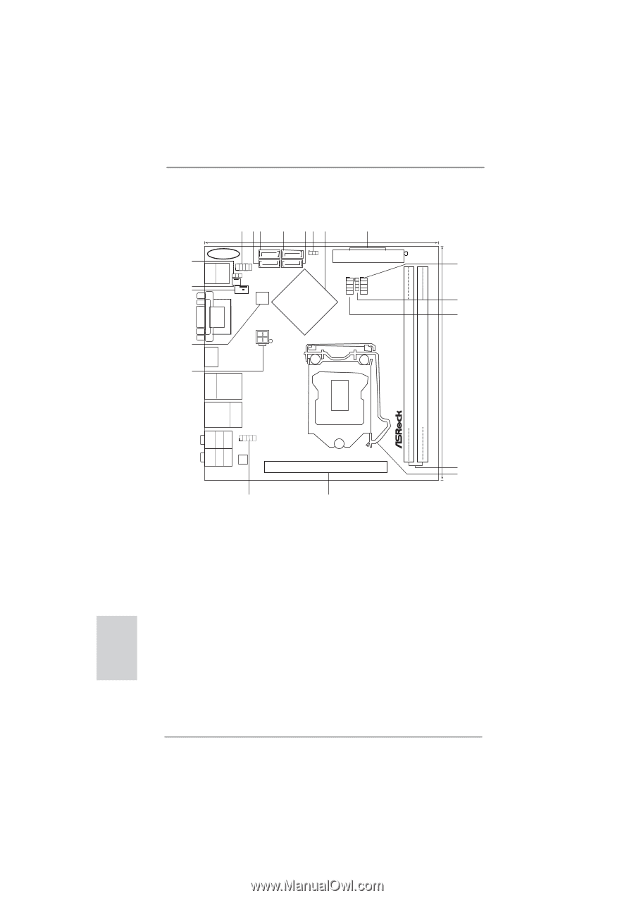
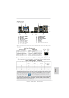
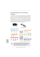
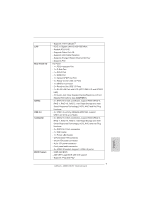
Motherboard Layout 1 23 4 56 7 8 17.0cm (6.7 in) SATA_0 (PORT 0) SATA_2 (PORT 4) CMOS 1 Battery CLRCMOS1 AT X P W R 1 20 PANEL1 PLED PWRBTN 9 USB 2.0 T: USB0 B: USB1 1 1 HDLED RESET PLED1 CHA_FAN1 SATA_1 (PORT 1) SATA_3 (PORT 3) 1 1 1 Gigabit LAN PS2 Keyboard 19 18 CPU_FAN1 64Mb BIOS Intel CIR1 USB6_7 USB8_9 10 Z68 11 Fast USB X ATX12V1 DVI_CON1 VGA1 17 17.0cm (6.7 in) DDR3_B1 (64 bit, 240-pin module) ErP/EuP Ready DDR3_A1 (64 bit, 240-pin module) DDR3 HDMI1 ESATA1 16 USB 2.0 T: USB2 B: USB3 Top: CTR BASS Center: REAR SPK Bottom: Optical SPDIF USB 3.0 T: USB4 Top: B: USB5 RJ-45 HD_AUDIO1 1 Z68M-ITX/HT AUDIO CODEC PCIE1 12 HDMI 1.4a USB 3.0 Designed in Taipei RoHS 13 Top: LINE IN Center: FRONT Bottom: MIC IN 15 14 1 System Panel Header (PANEL1, White) 12 2 x 240-pin DDR3 DIMM Slots 2 SATA3 Connector (SATA_1 (PORT 1), White) (Dual Channel: DDR3_A1, DDR3_B1, Blue) 3 SATA3 Connector (SATA_0 (PORT 0), White) 13 1155-Pin CPU Socket 4 SATA2 Connector (SATA_2 (PORT 4), Blue) 14 PCI Express 2.0 x16 Slot (PCIE1, Blue) 5 SATA2 Connector (SATA_3 (PORT 3), Blue) 15 Front Panel Audio Header 6 Clear CMOS Jumper (CLRCMOS1) (HD_AUDIO1, White) 7 Intel Z68 Chipset 16 ATX 12V Power Connector (ATX12V1) 8 ATX Power Connector (ATXPWR1) 17 64Mb SPI Flash 9 USB 2.0 Header (USB8_9, Blue) 18 CPU Fan Connector (CPU_FAN1) 10 Consumer Infrared Module Header (CIR1) 19 Chassis Fan Connector (CHA_FAN1) 11 USB 2.0 Header (USB6_7, Blue) 20 Power LED Header (PLED1) English 2 ASRock Z68M-ITX/HT Motherboard
-
 1
1 -
 2
2 -
 3
3 -
 4
4 -
 5
5 -
 6
6 -
 7
7 -
 8
8 -
9
-
10
-
11
-
12
-
13
-
14
-
15
-
16
-
17
-
18
-
19
-
20
-
21
-
22
-
23
-
24
-
25
-
26
-
27
-
28
-
29
-
30
-
31
-
32
-
33
-
34
-
35
-
36
-
37
-
38
-
39
-
40
-
41
-
42
-
43
-
44
-
45
-
46
-
47
-
48
-
49
-
50
-
51
-
52
-
53
-
54
-
55
-
56
-
57
-
58
-
59
-
60
-
61
-
62
-
63
-
64
-
65
-
66
-
67
-
68
-
69
-
70
-
71
-
72
-
73
-
74
-
75
-
76
-
77
-
78
-
79
-
80
-
81
-
82
-
83
-
84
-
85
-
86
-
87
-
88
-
89
-
90
-
91
-
92
-
93
-
94
-
95
-
96
-
97
-
98
-
99
-
100
-
101
-
102
-
103
-
104
-
105
-
106
-
107
-
108
-
109
-
110
-
111
-
112
-
113
-
114
-
115
-
116
-
117
-
118
-
119
-
120
-
121
-
122
-
123
-
124
-
125
-
126
-
127
-
128
-
129
-
130
-
131
-
132
-
133
-
134
-
135
-
136
-
137
-
138
-
139
-
140
-
141
-
142
-
143
-
144
-
145
-
146
-
147
-
148
-
149
-
150
-
151
-
152
-
153
-
154
 |
 |