ASRock Z87 Extreme9/ac User Manual
ASRock Z87 Extreme9/ac Manual
 |
View all ASRock Z87 Extreme9/ac manuals
Add to My Manuals
Save this manual to your list of manuals |
ASRock Z87 Extreme9/ac manual content summary:
- ASRock Z87 Extreme9/ac | User Manual - Page 1
User Manual - ASRock Z87 Extreme9/ac | User Manual - Page 2
change without notice, and should not be constructed as a commitment by ASRock. ASRock assumes no responsibility for any errors or omissions that may appear in CALIFORNIA, USA ONLY The Lithium battery adopted on this motherboard contains Perchlorate, a toxic substance controlled in Perchlorate Best - ASRock Z87 Extreme9/ac | User Manual - Page 3
The terms HDMI™ and HDMI High-Definition Multimedia Interface, and the HDMI logo are trademarks or registered trademarks of HDMI Licensing LLC in the United States and other countries. Manufactured under license under U.S. Patent Nos: 5,956,674; 5,974,380; 6,487,535; 7,003,467 & other U.S. and - ASRock Z87 Extreme9/ac | User Manual - Page 4
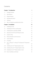
Unique Features 7 1.4 Motherboard Layout 11 1.5 I/O Panel 13 1.6 WiFi + BT Module and ASRock Wi-SD Box 15 Guide 36 2.9.1 Installing Two SLITM-Ready Graphics Cards 36 2.9.2 Installing Three SLITM-Ready Graphics Cards 38 2.9.3 Installing Four SLITM-Ready Graphics Cards 40 2.9.4 Driver - ASRock Z87 Extreme9/ac | User Manual - Page 5
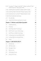
2.10.3 Installing Four CrossFireXTM-Ready Graphics Cards 45 2.10.4 Driver Installation and Setup 46 2.11 Thunderbolt 47 2.12 Dual LAN and Teaming Operation Guide 48 Chapter 3 Software and Utilities Operation 49 3.1 Installing Drivers 49 3.2 A-Tuning 50 3.3 Intel® Rapid Start Technology - ASRock Z87 Extreme9/ac | User Manual - Page 6
4.4.1 CPU Configuration 87 4.4.2 Chipset Configuration 89 4.4.3 Storage Configuration 91 4.4.4 Intel® Rapid Start Technology 93 4.4.5 Intel® Smart Connect Technology 94 4.4.6 Intel® Thunderbolt 95 4.4.7 Super IO Configuration 97 4.4.8 ACPI Configuration 98 4.4.9 USB Configuration - ASRock Z87 Extreme9/ac | User Manual - Page 7
the latest VGA cards and CPU support list on ASRock's website as well. ASRock website http://www.asrock.com. 1.1 Package Contents • ASRock Z87 Extreme9/ac Motherboard (ATX Form Factor) • ASRock Z87 Extreme9/ac Quick Installation Guide • ASRock Z87 Extreme9/ac Support CD • 10 x Serial ATA (SATA) Data - ASRock Z87 Extreme9/ac | User Manual - Page 8
.11ac WiFi • Socket LGA1150 to support 4th Gen Intel® CoreTM Processor • Digi Power Design • 12 Power Phase Design • Dual-Stack MOSFET (DSM) • Supports Intel® Turbo Boost 2.0 Technology • Supports Intel® K-Series unlocked CPUSupports • ASRock BCLK Full-range Overclocking • Intel® Z87 Memory • Dual - ASRock Z87 Extreme9/ac | User Manual - Page 9
Z87 Extreme9/ac Expansion Slot • 5 x PCI Express 3.0 x16 slots (PCIE1/PCIE2/PCIE3/PCIE4/ PCIE6: single Supports Intel® HD Graphics Built-in Visuals : Intel® Quick Sync Video with AVC, MVC (S3D) and MPEG-2 Full HW Encode1, Intel® InTruTM 3D, Intel® Clear Video HD Technology, Intel® InsiderTM, Intel - ASRock Z87 Extreme9/ac | User Manual - Page 10
• 1 x Giga PHY Intel® I217V, 1 x GigaLAN Intel® I211AT • Supports Intel® Remote Wake Technology (on Intel® I217V) • Supports Wake-On-LAN • Supports Dual LAN with Teaming • Supports Energy Efficient Ethernet 802.3az • Supports PXE Wireless LAN • Supports IEEE 802.11a/b/g/n/ac • Supports Dual-Band - ASRock Z87 Extreme9/ac | User Manual - Page 11
Z87 Extreme9/ac Storage • 6 x SATA3 6.0 Gb/s connectors by Intel® Z87, support RAID (RAID 0, RAID 1, RAID 5, RAID 10, Intel Rapid Storage Technology 12 and Intel Smart Response Technology), NCQ, AHCI and Hot Plug • 4 x SATA3 6.0 Gb/s connectors by ASMedia ASM1061, support NCQ, AHCI and Hot Plug ( - ASRock Z87 Extreme9/ac | User Manual - Page 12
Support CD • Drivers, Utilities, AntiVirus Software (Trial Version ready power supply is required) * For detailed product information, please visit our website: http://www.asrock.com Please realize that there is a certain risk involved with overclocking, including adjusting the setting in the BIOS - ASRock Z87 Extreme9/ac | User Manual - Page 13
Z87 Extreme9/ac 1.3 Unique Features ASRock A-Tuning A-Tuning is ASRock's multi purpose software suite with a new interface, more new features and improved utilities, including XFast RAM, Dehumidifier, Good Night LED, FAN-Tastic Tuning, OC Tweaker and a whole lot more. ASRock Instant Flash ASRock - ASRock Z87 Extreme9/ac | User Manual - Page 14
on automatically to dehumidify the system after entering S4/S5 state. ASRock Easy RAID Installer ASRock Easy RAID Installer can help you to copy the RAID driver from the support CD to your USB storage device. After copying the RAID driver to your USB storage device, please change "SATA Mode" to - ASRock Z87 Extreme9/ac | User Manual - Page 15
Z87 Extreme9/ac ASRock Easy Driver Installer For users that don't have an optical disk drive to install the drivers from our support CD, Easy Driver Installer is a handy tool in the UEFI that installs the LAN driver ! ASRock Home Cloud This motherboard supports remote wake with the onboard Intel LAN - ASRock Z87 Extreme9/ac | User Manual - Page 16
different fan speeds using the graph. The fans will automatically shift to the next speed level when the assigned temperature is met. ASRock Distortion-Free Slot ASRock's new pin design for the memory slots may appear to be the same as former designs, but actually effectively reduces distortion and - ASRock Z87 Extreme9/ac | User Manual - Page 17
Z87 Extreme9/ac 1.4 Motherboard Layout USB PCIE3 14 SATA3_0_1 SATA3_2_3 Z87 Extreme9/ac Super Intel 15 I/O PCIE4 Z87 16 SATA3_4_5 WiFi- 1 PLED PWRBTN 1 HDLED RESET PANEL1 BIOS_B_LED 64Mb BIOS BIOS_B 64Mb BIOS_A_LED CHA_FAN1 BIOS BIOS_A BIOS_SEL1 A B Reset Power 17 18 32 - ASRock Z87 Extreme9/ac | User Manual - Page 18
Connectors (SATA3_A1_A2) 13 SATA3 Connectors (SATA3_A3_A4) 14 SATA3 Connectors (SATA3_0_1) 15 SATA3 Connectors (SATA3_2_3) 16 SATA3 Connectors (SATA3_4_5) 17 BIOS Selection Switch (BIOS_SEL1) 18 Chassis Fan Connector (CHA_FAN1) 19 Power Switch (PWRBTN1) 20 Reset Switch (RSTBTN1) 21 Chassis Speaker - ASRock Z87 Extreme9/ac | User Manual - Page 19
Z87 Extreme9/ac 1.5 I/O Panel 79 1 2 3 4 5 6 8 10 19 18 17 16 15 14 13 12 11 No. Description 1 USB 2.0 Ports (USB01) 2 LAN RJ-45 Port (Intel® I211AT)* 3 Display Port Input (HDMI_DP_1) 4 eSATA Connector*** 5 USB 3.0 Ports (USB3_23) (ASMedia Hub) 6 USB 3.0 Ports (USB3_45) 7 Central / - ASRock Z87 Extreme9/ac | User Manual - Page 20
use the Rear Speaker, Central/Bass, and Front Speaker, or select "Realtek HDA Audio 2nd output" to use the front panel audio. *** The eSATA connector supports SATA with cables within 1 meters. English 14 - ASRock Z87 Extreme9/ac | User Manual - Page 21
Z87 Extreme9/ac 1.6 WiFi + BT Module and ASRock Wi-SD Box WiFi + BT Module This motherboard comes with an exclusive WiFi 802.11 a/b/g/n/ac + BT v4.0 module that offers support for WiFi 802.11 a/b/g/n/ac connectivity standards and Bluetooth v4.0. WiFi + BT module is an easy-to-use wireless local area - ASRock Z87 Extreme9/ac | User Manual - Page 22
Wi-SD Box Thanks to the excellent placement of antennas, ASRock Wi-SD Box comes with two invisible antennas (placed in a vertical/horizontal position), hidden inside the USB 3.0 ports for easier USB 3.0 device access, 1 SD Card slot and 1 rack for SSD placement. Wi-SD ASRock Wi-SD Box English 16 - ASRock Z87 Extreme9/ac | User Manual - Page 23
Z87 Extreme9/ac Installing the ASRock Wi-SD Box Step 1 Prepare the bundled ASRock Wi-SD Box and Wi-SD screws. Step 2 Plug the Front USB 3.0 cable into the USB 3.0 Wi-SD header on the Wi-SD Box. Step 3 - ASRock Z87 Extreme9/ac | User Manual - Page 24
USB 3.0 USB 3.0 Step 5 Screw ASRock Wi-SD Box to the drive bay with screws. Step 6 Attach the cords to the WiFi + BT module on your motherboard. Step 7 Connect the floppy drive 4 pin power Wi-SD connector to the Wi-SD Box. Step 8 Plug the Front USB 3.0 cable into the USB 3.0 header - ASRock Z87 Extreme9/ac | User Manual - Page 25
Z87 Extreme9/ac Chapter 2 Installation This is an ATX form factor motherboard. Before you install the motherboard, study the configuration of your chassis to ensure that the motherboard fits into it. Pre-installation Precautions Take note of the following precautions before you install motherboard - ASRock Z87 Extreme9/ac | User Manual - Page 26
2.1 Installing the CPU 1. Before you insert the 1150-Pin CPU into the socket, please check if the PnP cap is on the socket, if the CPU surface is unclean, or if there are any bent pins in the socket. Do not force to insert the CPU into the socket if above situation is found. Otherwise, the CPU will - ASRock Z87 Extreme9/ac | User Manual - Page 27
Z87 Extreme9/ac 3 4 5 21 English - ASRock Z87 Extreme9/ac | User Manual - Page 28
Please save and replace the cover if the processor is removed. The cover must be placed if you wish to return the motherboard for after service. 22 English - ASRock Z87 Extreme9/ac | User Manual - Page 29
2.2 Installing the CPU Fan and Heatsink Z87 Extreme9/ac 1 2 CPU_FAN 23 English - ASRock Z87 Extreme9/ac | User Manual - Page 30
2.3 Installing Memory Modules (DIMM) This motherboard provides four 240-pin DDR3 (Double Data Rate 3) DIMM slots, and supports Dual Channel Memory Technology. 1. For dual channel configuration, you always need to install identical (the same brand, speed, size and chip-type) DDR3 DIMM pairs. 2. - ASRock Z87 Extreme9/ac | User Manual - Page 31
Z87 Extreme9/ac 1 2 3 25 English - ASRock Z87 Extreme9/ac | User Manual - Page 32
2.4 Expansion Slots (PCI and PCI Express Slots) There are 6 PCI Express slots and 1 mini-PCI Express slot on the motherboard. Before installing an expansion card, please make sure that the power supply is switched off or the power cord is unplugged. Please read the documentation - ASRock Z87 Extreme9/ac | User Manual - Page 33
Z87 Extreme9/ac 2.5 Jumpers Setup The illustration shows how jumpers are setup. When the jumper cap . However, please do not clear the CMOS right after you update the BIOS. If you need to clear the CMOS when you just finish updating the BIOS, you must boot up the system first, and then shut it down - ASRock Z87 Extreme9/ac | User Manual - Page 34
jumper caps over the headers and connectors will cause permanent damage to the motherboard. System Panel Header (9-pin PANEL1) (see p.11, No. 22 (Reset Switch): Connect to the reset switch on the chassis front panel. Press the reset switch to restart the computer if the computer freezes and fails to - ASRock Z87 Extreme9/ac | User Manual - Page 35
SATA3_0_1 SATA3_A3_A4 SATA3_A1_A2 English Z87 Extreme9/ac Power LED Header (3-pin the internal SATA3_A4 will not function. To minimize the boot time, use Intel® Z87 SATA ports (SATA3_0) for your bootable devices. USB 2.0 Headers (9- motherboard. Each USB 2.0 header can support two ports. 29 - ASRock Z87 Extreme9/ac | User Manual - Page 36
are two headers on this motherboard. Each USB 3.0 header can support two ports. Front Panel supports Jack Sensing, but the panel wire on the chassis must support HDA to function correctly. Please follow the instructions in our manual and chassis manual to install your system. 2. If you use an AC - ASRock Z87 Extreme9/ac | User Manual - Page 37
Z87 Extreme9/ac Chassis and Power Fan Connectors (4-pin CHA_FAN1) (see p.11, No. 18) (see p.11, No. 2) (8-pin ATX12V2) (see p.11, No. 3) 12 24 1 13 8 5 4 1 This motherboard provides a 24-pin ATX power connector. To use a 20-pin ATX power supply, please plug it along Pin 1 and Pin - ASRock Z87 Extreme9/ac | User Manual - Page 38
DDTR#1 DDSR#1 CCTS#1 1 RRI#1 RRTS#1 GND TTXD1 DDCD#1 Please connect this connector with a hard disk power connector when two graphics cards are installed on this motherboard. This header supports an optional wireless transmitting and receiving infrared module. This COM1 header - ASRock Z87 Extreme9/ac | User Manual - Page 39
Z87 Extreme9/ac 2.7 Smart Switches The motherboard has three smart switches: BIOS files to the primary BIOS to ensure normal system operation. For safety issues, users are not able to update the backup BIOS manually. Users may refer to the BIOS LEDs (BIOS_A_LED or BIOS_B_LED) to identify which BIOS - ASRock Z87 Extreme9/ac | User Manual - Page 40
. Debug is used to provide code information, which makes troubleshooting even easier. Please see the diagrams below for reading the Dr. Debug codes. Code Description 00 Please check if the CPU is installed correctly and then clear CMOS. 0d Problem related to memory, VGA card or other devices - ASRock Z87 Extreme9/ac | User Manual - Page 41
Z87 Extreme9/ac b4 Problem related to USB devices. Please try removing all USB devices. b7 Problem related to memory. Please re-install the CPU and memory then clear CMOS. If the problem still exists, please install only one memory module or try using other memory modules. d6 The VGA could - ASRock Z87 Extreme9/ac | User Manual - Page 42
, 4-Way SLITM and Quad SLITM Operation Guide This motherboard supports NVIDIA® SLITM , 3-way SLITM, 4-way only use identical SLITM-ready graphics cards that are NVIDIA® certified. 2. Make sure that your graphics card driver supports NVIDIA® SLITM technology. Download the drivers from the NVIDIA® - ASRock Z87 Extreme9/ac | User Manual - Page 43
Z87 Extreme9/ac Step 3 Align and insert the ASRock SLI_ Bridge_3S Card to the goldfingers on each graphics card. Make sure the ASRock SLI_ Bridge_3S Card is firmly in place. SLI_Bridge_3S Card ASRock SLI_Bridge_3S Card Step 4 Connect a VGA cable or a DVI cable to the monitor connector or the DVI - ASRock Z87 Extreme9/ac | User Manual - Page 44
2.9.2 Installing Three SLITM-Ready Graphics Cards Step 1 Insert one graphics card into PCIE1 slot, another graphics card to PCIE3 connected. Repeat this step on the three graphics cards. Step 3 Align and insert the ASRock 3-Way SLI Bridge Card to the goldfingers on each graphics card. Make sure the - ASRock Z87 Extreme9/ac | User Manual - Page 45
Z87 Extreme9/ac Step 4 Connect a VGA cable or a DVI cable to the monitor connector or the DVI connector of the graphics card that is inserted to PCIE1 slot. 39 English - ASRock Z87 Extreme9/ac | User Manual - Page 46
2.9.3 Installing Four SLITM-Ready Graphics Cards Step 1 Insert one graphics card into the cards. SLI_Bridge_3S Card Step 3 Align and insert an ASRock SLI Bridge Card to the goldfingers of the first and second graphics card. Install the second ASRock SLI Bridge Card to the goldfingers of the third - ASRock Z87 Extreme9/ac | User Manual - Page 47
Z87 Extreme9/ac Step 4 Connect a VGA cable or a DVI cable to the monitor connector or the DVI connector of the graphics card that is inserted to PCIE1 slot. 41 English - ASRock Z87 Extreme9/ac | User Manual - Page 48
Installation and Setup Install the graphics card drivers to your system. After that, you can enable the Multi-Graphics Processing Unit (GPU) in the NVIDIA® nView system tray utility. Please follow the below - ASRock Z87 Extreme9/ac | User Manual - Page 49
Z87 Extreme9/ac 2.10 CrossFireXTM, 3-Way CrossFireXTM, 4-Way CrossFireXTM and Quad CrossFireXTM Operation Guide This motherboard supports CrossFireXTM, Please refer to AMD graphics card manuals for detailed installation guide. 2.10.1 Installing Two CrossFireXTM-Ready Graphics Cards Step 1 Insert one - ASRock Z87 Extreme9/ac | User Manual - Page 50
card that is inserted to PCIE2 slot. 2.10.2 Installing Three CrossFireXTM-Ready Graphics Cards Step 1 Insert one graphics card into PCIE1 slot, is provided with the graphics card you purchase, not bundled with this motherboard. Please refer to your graphics card vendor for details.) Step 3 Connect - ASRock Z87 Extreme9/ac | User Manual - Page 51
Z87 Extreme9/ac 2.10.3 Installing Four CrossFireXTM-Ready Graphics Cards Step 1 Insert one graphics card . (The CrossFire Bridge is provided with the graphics card you purchase, not bundled with this motherboard. Please refer to your graphics card vendor for details.) Step 3 Connect a VGA cable or - ASRock Z87 Extreme9/ac | User Manual - Page 52
optional download. We recommend using this utility to uninstall any previously installed Catalyst drivers prior to installation. Please check AMD's website for AMD driver updates. Step 3 Install the required drivers and CATALYST Control Center then restart your computer. Please check AMD's website - ASRock Z87 Extreme9/ac | User Manual - Page 53
Z87 Extreme9/ac 2.11 Thunderbolt This motherboard has two thunderbolt connectors that support video output from internal VGA. Thunderbolt cables are provided by your monitor supplier. 2. Thunderbolt ports on this motherboard supports DisplayPort 1.2 Re-drive (Pass-Through) mode with HBR2 Data Rates. - ASRock Z87 Extreme9/ac | User Manual - Page 54
and Teaming Operation Guide Dual LAN with Teaming enabled on this motherboard allows two single supports Teaming (IEEE 802.3ad Link Aggregation). You can specify a preferred adapter in Intel PROSet. Under normal conditions, the Primary adapter handles all non-TCP/IP traffic. The Secondary adapter - ASRock Z87 Extreme9/ac | User Manual - Page 55
Z87 Extreme9/ac Chapter 3 Software and Utilities Operation 3.1 Installing Drivers The Support CD that comes with the motherboard contains necessary drivers and useful utilities that enhance the motherboard's features. Running The Support CD To begin using the support CD, insert the CD into your CD- - ASRock Z87 Extreme9/ac | User Manual - Page 56
whole lot more. 3.2.1 Installing A-Tuning When you install the all-in-one driver to your system from ASRock's support CD, A-Tuning will be auto-installed as well. After the installation, OC Tweaker, System Info and Tech Service. Operation Mode Choose an operation mode for your computer. 50 English - ASRock Z87 Extreme9/ac | User Manual - Page 57
Tools Various tools and utilities. Z87 Extreme9/ac XFast RAM Boost the system's performance and extend the shift to the next speed level when the assigned temperature is met. Dehumidifier Prevent motherboard damages due to dampness. Enable this function and configure the period of time until - ASRock Z87 Extreme9/ac | User Manual - Page 58
OC Tweaker Configurations for overclocking the system. System Info View information about the system. Tech Service Contact Tech Service. 52 English - ASRock Z87 Extreme9/ac | User Manual - Page 59
Z87 Extreme9/ac 3.3 Intel® Rapid Start Technology Intel mode. 3.3.1 System Requirements • Confirm whether your motherboard supports this feature. • Operating system: Microsoft Windows instructions below. There are certain risks. Please backup any important data before operating to avoid loss. 1. Press - ASRock Z87 Extreme9/ac | User Manual - Page 60
F2 to enter BIOS, then go to Advanced ‐> Storage Configuration and change SATA Mode to AHCI. Press F10 to save changes and exit. 5. Enter Windows 8/7. Windows will discover the new device and install AHCI drivers automatically. 3.3.2 Setup Guide Configuring Rapid Start Step 1 Run ASRock Rapid Start - ASRock Z87 Extreme9/ac | User Manual - Page 61
Z87 Extreme9/ac Step 3 When prompted to restart after the setup, click Yes to reboot. Step 4 Double-click the Intel® Rapid Start Technology Manager icon system tray. in the Windows 55 English - ASRock Z87 Extreme9/ac | User Manual - Page 62
Step 5 Make sure Rapid Start is on. Drag the slider to configure the time. For example, if the timer value is set to ten minutes, the system will enable Rapid Start mode after entering sleep state for ten minutes. If the timer is set to 0 minutes, Windows will immediately enable Rapid Start mode as - ASRock Z87 Extreme9/ac | User Manual - Page 63
Z87 Extreme9/ac state for a period of time. The power of the computer in Rapid Start mode can be cut off, it will not cause data loss of - ASRock Z87 Extreme9/ac | User Manual - Page 64
Intel® Smart Connect Technology is a feature that periodically wakes your computer from Windows® sleep state to refresh email or social networking applications. It saves your waiting time and keeps the content always up-to-date. 3.4.1 System Requirements • Confirm whether your motherboard supports - ASRock Z87 Extreme9/ac | User Manual - Page 65
Z87 Extreme9/ac 3.4.2 Setup Guide Installing ASRock Smart Connect Utility Step 1 Install ASRock Smart Connect Utility, which is located in the folder at the following path of the Support CD: \ ASRock Utility > Smart Connect. Step 2 Once installed, run ASRock Smart Connect from your desktop or go to - ASRock Z87 Extreme9/ac | User Manual - Page 66
Step 3 Click the Add button. Take Foxmail as an example, add Foxmail to the Application list. Step 4 Select Foxmail from the Application List, then click the arrow pointing right to add this application to the Smart Connect List. Step 5 Click Apply to enable Smart Connect. 60 English - ASRock Z87 Extreme9/ac | User Manual - Page 67
Z87 Extreme9/ac Step 6 Double-click the Intel® Smart Connect Technology Manager icon Windows system tray. in the Step 7 Drag the slider to configure how often the system will connect to the network - ASRock Z87 Extreme9/ac | User Manual - Page 68
state again. 5. Upon waking up the system, you will find the new mail that were sent to you during sleep state are already updated and ready to be read in Foxmail. 62 English - ASRock Z87 Extreme9/ac | User Manual - Page 69
Z87 Extreme9/ac 3.5 Intel® Remote Wake Technology Intel® Remote Wake Technology allows you to use programs or services over the Internet to wake up your home computer from energy efficient sleep mode. Before configuring this feature, verify the following. • Remote Wake has been enabled in "Intel® - ASRock Z87 Extreme9/ac | User Manual - Page 70
Step 3 A new mesh window will pop up. Enter a mesh name and password. Step 4 Select all the checkboxes and click Create Mesh. Downloading and Installing Mesh Agent Step 1 Click Install on the My Account page. Step 2 Select the mesh and download both files. Make sure both files are in the same - ASRock Z87 Extreme9/ac | User Manual - Page 71
Step 4 Click Install / Update. Z87 Extreme9/ac Step 5 Wait a minute for the New Machine to appear in "My Device". English 65 - ASRock Z87 Extreme9/ac | User Manual - Page 72
Step 6 Check whether "Intel Remote Wake" appeared or not. Waking up Your PC using PC Step 1 On the "My Devices" page, click on Power Actions. Step 2 Click on Wake or Sleep. 66 English - ASRock Z87 Extreme9/ac | User Manual - Page 73
Z87 Extreme9/ac Waking up Your PC Using Mobile Device Before waking up your home computer using a mobile device, please log out of MeshCentral on other previously used - ASRock Z87 Extreme9/ac | User Manual - Page 74
that "Remote Wake" has been enabled in "Intel® Smart Connect Technology Manager". Setup Guide Step 1 Download and install the Streamer on your home computer, which is located in the folder at the following path of the Support CD: \ ASRock Utility > Splashtop Streamer. Then enter your Splashtop - ASRock Z87 Extreme9/ac | User Manual - Page 75
Z87 Extreme9/ac Using Remote Control Step 1 In "Splashtop 2", tap an online machine from the list to connect to your home computer. Step 2 Start remotely accessing your home computer. The functionality and price of the Splashtop APP and subscription fee is subject to change. Please check www. - ASRock Z87 Extreme9/ac | User Manual - Page 76
Accessing Data Playing Video 70 English - ASRock Z87 Extreme9/ac | User Manual - Page 77
Z87 Extreme9/ac 3.6 Start8 For those Windows 8 users who miss the Start Menu, Start8 is Installing Start8 Install Start8, which is located in the folder at the following path of the Support CD: \ ASRock Utility > Start8. 3.6.2 Configuring Start8 Style Select between the Windows 7 style and Windows 8 - ASRock Z87 Extreme9/ac | User Manual - Page 78
Configure Configure provides configuration options, including icon sizes, which shortcuts you want Start Menu to display, quick access to recently used apps, the functionality of the power button, and more. Control 72 English - ASRock Z87 Extreme9/ac | User Manual - Page 79
Z87 Extreme9/ac Control lets you configure what a click on the start button or a press on the Windows key does. Desktop Desktop allows you to disable the hot corners when you are working on the desktop. It also lets you - ASRock Z87 Extreme9/ac | User Manual - Page 80
ASRock Interactive UEFI is a blend of system configuration tools, cool sound effects and stunning visuals. Not only will it make BIOS setup Utility by pressing or right after you power on the computer, otherwise, the Power-On-Self-Test (POST) will continue with its test routines. If - ASRock Z87 Extreme9/ac | User Manual - Page 81
Z87 Extreme9/ac 4.1.2 Navigation Keys Use < > key or < > key to choose among the selections on the menu bar, and use < > key or < > key to move the cursor up or down to select items, then press to get into the sub screen. You can also use the mouse to click your required item. Please check - ASRock Z87 Extreme9/ac | User Manual - Page 82
, the Main screen will appear and display the system overview. Active Page on Entry Select the default page when entering the UEFI setup utility. UEFI Guide UEFI Guide is a quick tutorial for ASRock's UEFI setup Utility. You may abort the tutorial by pressing "esc". 76 English - ASRock Z87 Extreme9/ac | User Manual - Page 83
set up overclocking features. Z87 Extreme9/ac Because the UEFI software system performance. This option appears only when your CPU supports this function. This option appears only when you adopt that overclocing may cause damage to your CPU and motherboard. It should be done at your own risk and - ASRock Z87 Extreme9/ac | User Manual - Page 84
. Spread Spectrum Enable Spread Spectrum to reduce electromagnetic interference for passing EMI tests. Disable to achieve higher clock speeds when overclocking. Intel SpeedStep Technology Intel SpeedStep technology allows processors to switch between multiple frequencies and voltage points for - ASRock Z87 Extreme9/ac | User Manual - Page 85
Z87 Extreme9/ac Short Duration Power Limit Configure Package Power Limit 2 in watts. When the limit is Select Auto for optimized settings. DRAM Frequency If [Auto] is selected, the motherboard will detect the memory module(s) inserted and assign the appropriate frequency automatically. 79 English - ASRock Z87 Extreme9/ac | User Manual - Page 86
DRAM Configuration DRAM Tweaker Fine tune the DRAM settings by leaving marks in checkboxes. Click OK to confirm and apply your new settings. CAS# Latency (tCL) The time between sending a column address to the memory and the beginning of the data in response. RAS# to CAS# Delay (tRCD) The number of - ASRock Z87 Extreme9/ac | User Manual - Page 87
Z87 Extreme9/ac Command Rate (CR) The delay between when a memory chip is selected and when the first active command can be issued. Write Recovery Time (tWR) The - ASRock Z87 Extreme9/ac | User Manual - Page 88
write to read delay. tWRRDDR Configure between module write to read delay from different ranks. tWRRDDD Use this to change DRAM tRRSR Auto/Manual settings. The default is [Auto]. Configure between module write to read delay from different DIMMs. tWRWR Configure between module write to write delay - ASRock Z87 Extreme9/ac | User Manual - Page 89
Z87 Extreme9/ac IO-L (CHB) Configure IO latency for channel B. ODT WR (CHA) Configure the memory on die termination resistors' WR for channel A. ODT WR (CHB) Configure the memory on die termination resistors' WR for channel B. ODT NOM (CHA) Use this to change ODT (CHA) Auto/Manual settings. The - ASRock Z87 Extreme9/ac | User Manual - Page 90
CPU Cache Voltage Offset Configure the voltage for the CPU Cache. Setting the voltage higher may increase system stability when overclocking. System Agent Voltage Offset Configure the voltage for the System Agent. Setting the voltage higher may increase system stability when overclocking. CPU Analog - ASRock Z87 Extreme9/ac | User Manual - Page 91
DRAM Voltage Use this to configure DRAM Voltage. The default value is [Auto]. PCH 1.05V Voltage Chipset 1.05V Voltage. Use default settings for best performance. PCH 1.5V Voltage I/O 1.5V Voltage. Use default settings for best performance. Z87 Extreme9/ac English 85 - ASRock Z87 Extreme9/ac | User Manual - Page 92
you may set the configurations for the following items: CPU Configuration, Chipset Configuration, Storage Configuration, Intel® Rapid Start Technology, Intel® Smart Connect Technology, Intel® Thunderbolt, Super IO Configuration, ACPI Configuration and USB Configuration. Setting wrong values in this - ASRock Z87 Extreme9/ac | User Manual - Page 93
4.4.1 CPU Configuration Z87 Extreme9/ac Intel Hyper Threading Technology Intel Hyper Threading Technology allows multiple C3 State Support Enable C3 sleep state for lower power consumption. CPU C6 State Support Enable C6 deep sleep state for lower power consumption. CPU C7 State Support Enable C7 - ASRock Z87 Extreme9/ac | User Manual - Page 94
C State Support for power saving. CPU Thermal Throttling Enable CPU internal thermal control mechanisms to keep the CPU from overheating. No-Execute Memory Protection Processors with No-Execution Memory Protection Technology may prevent certain classes of malicious buffer overflow attacks. Intel - ASRock Z87 Extreme9/ac | User Manual - Page 95
4.4.2 Chipset Configuration Z87 Extreme9/ac Primary Graphics Adapter Select a primary VGA. VT-d Intel® Virtualization Technology for Directed I/O helps your virtual machine monitor better utilize hardware by improving application compatibility and reliability, and providing additional levels of - ASRock Z87 Extreme9/ac | User Manual - Page 96
Enable or disable the onboard network interface controller. Deep Sleep Configure deep sleep mode for power saving when the computer is shut down. Restore on AC/Power Loss Select the power state after a power failure. If [Power Off] is selected, the power will remain off when the power recovers. If - ASRock Z87 Extreme9/ac | User Manual - Page 97
Configuration Z87 Extreme9/ac SATA Controller(s) Enable/disable the SATA controllers. SATA Mode Selection IDE: For better compatibility. AHCI: Supports new features that improve performance. RAID: Combine multiple disk drives into a logical unit. AHCI (Advanced Host Controller Interface) supports - ASRock Z87 Extreme9/ac | User Manual - Page 98
for computer hard disk drives to detect and report on various indicators of reliability. ASMedia SATA3 Mode IDE: For better compatibility. AHCI: Supports new features that improve performance. SATA Boot ROM Enable to load ASMedia option ROM for better compatibility. Disable for faster boot time. 92 - ASRock Z87 Extreme9/ac | User Manual - Page 99
4.4.4 Intel® Rapid Start Technology Z87 Extreme9/ac Intel® Rapid Start Technology Intel® Rapid Start Technology is a new zero power hibernation mode which allows users to resume in just 5-6 seconds. English 93 - ASRock Z87 Extreme9/ac | User Manual - Page 100
4.4.5 Intel® Smart Connect Technology Intel® Smart Connect Technology Intel® Smart Connect Technology automatically updates your email and social networks, such as Twitter, Facebook, etc. while the computer is in sleep mode. 94 English - ASRock Z87 Extreme9/ac | User Manual - Page 101
4.4.6 Intel® Thunderbolt Z87 Extreme9/ac Thunderbolt Support Enable/Disable the onboard Thunderbolt ports. Security Level , and show warning messages if the devices aren't certified. Or select DP++ to support DP 1.2. Wake From Thunderbolt Devices Allow the system to be waked up by Thunderbolt - ASRock Z87 Extreme9/ac | User Manual - Page 102
TBT Device IO resource Support Enable IO Resource Support if your older Thunderbolt devices have trouble working properly. Thunderbolt PCIe Cache-line Size@ Configure the cache-line size of the Thunderbolt PCIe subtree. 96 English - ASRock Z87 Extreme9/ac | User Manual - Page 103
4.4.7 Super IO Configuration Z87 Extreme9/ac Serial Port Enable or disable the Serial port. Serial Port Address Select the address of the Serial port. Infrared Port Enable or disable the Infrared port. 97 English - ASRock Z87 Extreme9/ac | User Manual - Page 104
Enable to enter the operating system after S3 only when the hard disk is ready, this is recommended for better system stability. ACPI HPET Table Enable the High Precision Event Timer for better performance and to pass WHQL tests. PS/2 Keyboard Power On Allow the system to be waked up by a PS - ASRock Z87 Extreme9/ac | User Manual - Page 105
Z87 Extreme9/ac Ring-In Power On Allow the system to be waked up by onboard COM port modem Ring-In signals. RTC Alarm Power On Allow the - ASRock Z87 Extreme9/ac | User Manual - Page 106
4.4.9 USB Configuration USB Controller Enable or disable all the USB ports. Intel USB 3.0 Mode Enable or disable all the USB 3.0 ports. Legacy USB Support Enable or disable Legacy OS Support for USB 2.0 devices. If you encounter USB compatibility issues it is recommended to disable legacy USB - ASRock Z87 Extreme9/ac | User Manual - Page 107
4.5 Tools Z87 Extreme9/ac System Browser ASRock System Browser Service Contact ASRock Tech Service if you are having trouble with your PC. Please setup network configuration before using UEFI Tech Service. Easy RAID Installer Easy RAID Installer helps you to copy the RAID driver from the support - ASRock Z87 Extreme9/ac | User Manual - Page 108
current working ROM image to the secondary flash ROM. Internet Flash ASRock Internet Flash downloads and updates the latest UEFI firmware version from for you. Please setup network configuration before using Internet Flash. *For BIOS backup and recovery purpose, it is recommended to plug in your USB - ASRock Z87 Extreme9/ac | User Manual - Page 109
Z87 Extreme9/ac Dehumidifier Function If Dehumidifier Function is enabled, the computer will power on the fan speed. Max: 255 Min: 1 Save User Default Type a profile name and press enter to save your settings as user default. Load User Default Load previously saved user defaults. 103 English - ASRock Z87 Extreme9/ac | User Manual - Page 110
Monitoring Screen This section allows you to monitor the status of the hardware on your system, including the parameters of the CPU temperature, motherboard temperature, fan speed and voltage. CPU Fan 1 & 2 Setting Select a fan mode for CPU Fans 1&2, or choose Customize to set 5 CPU temperatures and - ASRock Z87 Extreme9/ac | User Manual - Page 111
Z87 Extreme9/ac 4.7 Boot Screen This section displays the available devices on your system mode you may not boot from an USB storage device. Ultra Fast mode is only supported by Windows 8 and the VBIOS must support UEFI GOP if you are using an external graphics card. Please notice that Ultra Fast - ASRock Z87 Extreme9/ac | User Manual - Page 112
the number of attempts to boot until the system automatically restores the default settings. CSM (Compatibility Support Module) CSM Enable to launch the Compatibility Support Module. Please do not disable unless you're running a WHCK test. If you are using Windows 8 64-bit and all of your devices - ASRock Z87 Extreme9/ac | User Manual - Page 113
Z87 Extreme9/ac Launch PXE OpROM Policy Select UEFI only to run those that support UEFI option ROM only. Select Legacy only to run those that support legacy option ROM only. Do not launch? Launch Storage OpROM Policy Select UEFI only to run those that support UEFI option ROM only. Select Legacy only - ASRock Z87 Extreme9/ac | User Manual - Page 114
change the password for the administrator account. Only the administrator has authority to change the settings in the UEFI Setup Utility. Leave it blank and press enter to remove the password. User Password Set or change the password for the user account. Users are unable to change the settings in - ASRock Z87 Extreme9/ac | User Manual - Page 115
4.9 Exit Screen Z87 Extreme9/ac Save Changes and Exit When you select this option the following message, "Save configuration changes and exit setup?" will pop out. Select [OK] to save - ASRock Z87 Extreme9/ac | User Manual - Page 116
or want to know more about ASRock, you're welcome to visit ASRock's website at http://www.asrock.com; or you may contact your dealer for further information. For technical questions, please submit a support request form at http://www.asrock.com/support/tsd.asp ASRock Incorporation 2F., No.37, Sec
-
 1
1 -
 2
2 -
 3
3 -
 4
4 -
 5
5 -
 6
6 -
 7
7 -
8
-
9
-
10
-
11
-
12
-
13
-
14
-
15
-
16
-
17
-
18
-
19
-
20
-
21
-
22
-
23
-
24
-
25
-
26
-
27
-
28
-
29
-
30
-
31
-
32
-
33
-
34
-
35
-
36
-
37
-
38
-
39
-
40
-
41
-
42
-
43
-
44
-
45
-
46
-
47
-
48
-
49
-
50
-
51
-
52
-
53
-
54
-
55
-
56
-
57
-
58
-
59
-
60
-
61
-
62
-
63
-
64
-
65
-
66
-
67
-
68
-
69
-
70
-
71
-
72
-
73
-
74
-
75
-
76
-
77
-
78
-
79
-
80
-
81
-
82
-
83
-
84
-
85
-
86
-
87
-
88
-
89
-
90
-
91
-
92
-
93
-
94
-
95
-
96
-
97
-
98
-
99
-
100
-
101
-
102
-
103
-
104
-
105
-
106
-
107
-
108
-
109
-
110
-
111
-
112
-
113
-
114
-
115
-
116
 |
 |

User Manual