ASRock Z97 Extreme4/3.1 Quick Installation Guide
ASRock Z97 Extreme4/3.1 Manual
 |
View all ASRock Z97 Extreme4/3.1 manuals
Add to My Manuals
Save this manual to your list of manuals |
ASRock Z97 Extreme4/3.1 manual content summary:
- ASRock Z97 Extreme4/3.1 | Quick Installation Guide - Page 1
documentation are furnished for informational use only and subject to change without notice, and should not be constructed as a commitment by ASRock. ASRock assumes no responsibility for any errors or omissions that may appear in this documentation. With respect to the contents of this documentation - ASRock Z97 Extreme4/3.1 | Quick Installation Guide - Page 2
he terms HDMI™ and HDMI High-Deinition Multimedia Interface, and the HDMI logo are trademarks or registered trademarks of HDMI Licensing LLC in the United States and other countries. Manufactured under license under U.S. Patent Nos: 5,956,674; 5,974,380; 6,487,535; 7,003,467 & other U.S. and - ASRock Z97 Extreme4/3.1 | Quick Installation Guide - Page 3
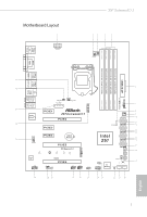
USB6 B: USB7 Top: RJ-45 Front USB 3.0 USB3_0_1 1 Top: Central/Bass LINE IN Center: REAR SPK Bottom: Optical SPDIF CHA_FAN3 CHA_FAN2 PCIE_PWR1 TPMS1 7 Top: Center: FRONT Bottom: MIC IN 33 PCIE1 1 Z97 Extreme4/3.1 Purity SoundTM 2 PCIE2 32 8 9 CHA_FAN1 10 SATA3_A1 SATA3_A0 - ASRock Z97 Extreme4/3.1 | Quick Installation Guide - Page 4
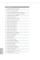
Switch (RSTBTN1) 22 Clear CMOS Switch 23 Power LED Header (PLED1) 24 System Panel Header (PANEL1) 25 Chassis Speaker Header (SPEAKER1) 26 USB 2.0 Header (USB4_5) 27 USB 2.0 Header (USB2_3) 28 Clear CMOS Jumper (CLRMOS1) 29 Power Fan Connector (PWR_FAN1) 30 COM Port Header (COM1) 31 Front Panel Audio - ASRock Z97 Extreme4/3.1 | Quick Installation Guide - Page 5
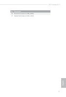
No. Description 34 Chassis Fan Connector (CHA_FAN3) 35 Chassis Fan Connector (CHA_FAN2) Z97 Extreme4/3.1 English 3 - ASRock Z97 Extreme4/3.1 | Quick Installation Guide - Page 6
I/O Panel 1 2 3 4 68 5 79 16 15 14 13 12 11 10 No. Description 1 USB 2.0 Ports (USB01) 2 D-Sub Port 3 USB 3.0 Ports (USB3_45) (Intel® Z97) 4 USB 3.0 Ports (USB3_23) (Intel® Z97) 5 LAN RJ-45 Port* 6 Central / Bass (Orange) 7 Rear Speaker (Black) 8 Line In (Light Blue) 9 Front Speaker ( - ASRock Z97 Extreme4/3.1 | Quick Installation Guide - Page 7
Z97 Extreme4/3.1 * here are two LEDs on each LAN port. Please refer to the table below for the LAN port LED indications. ACT/LINK LED SPEED LED - ASRock Z97 Extreme4/3.1 | Quick Installation Guide - Page 8
• ASRock Z97 Extreme4/3.1 Motherboard (ATX Form Factor) • ASRock Z97 Extreme4/3.1 Quick Installation Guide • ASRock Z97 Extreme4/3.1 Support CD • 4 x Serial ATA (SATA) Data Cables (Optional) • 1 x HDD Saver Cable • 1 x I/O Shield • 1 x ASRock SLI_Bridge_2S Card • 1 x ASRock USB 3.1/A+C • 1 x Screw - ASRock Z97 Extreme4/3.1 | Quick Installation Guide - Page 9
Z97 Extreme4/3.1 1.2 Speciications Platform • ATX Form Factor • High Density Glass Fabric PCB CPU • Supports 5th Generation, New 4th and 4th Generation Intel® CoreTM i7/i5/i3/Pentium®/Celeron® Processors (Socket 1150) • Digi Power design • 12 Power Phase design • Supports Intel® Turbo Boost 2.0 - ASRock Z97 Extreme4/3.1 | Quick Installation Guide - Page 10
Ports Audio • 7.1 CH HD Audio with Content Protection (Realtek ALC1150 Audio Codec) • Premium Blu-ray Audio support • Supports Surge Protection (ASRock Full Spike Protection) • Supports Purity SoundTM 2 - Nichicon Fine Gold Series Audio Caps - 115dB SNR DAC with Diferential Ampliier - TI® NE5532 - ASRock Z97 Extreme4/3.1 | Quick Installation Guide - Page 11
Z97 Extreme4/3.1 LAN Rear Panel I/O ASRock USB 3.1/ A+C • Gigabit LAN 10/100/1000 Mb/s • Giga PHY Intel® I218V • Supports Intel® Remote Wake Technology • Supports Wake-On-LAN • Supports Lightning/ESD Protection (ASRock Full Spike Protection) • Supports Energy Eicient Ethernet 802.3az • Supports - ASRock Z97 Extreme4/3.1 | Quick Installation Guide - Page 12
PCIe Power Connector • 1 x Front Panel Audio Connector • 2 x USB 2.0 Headers (support 4 USB 2.0 ports) (Supports ESD Protection (ASRock Full Spike Protection)) • 1 x USB 3.0 Header (support 2 USB 3.0 ports) (Supports ESD Protection (ASRock Full Spike Protection)) • 1 x Dr. Debug with LED • 1 x Power - ASRock Z97 Extreme4/3.1 | Quick Installation Guide - Page 13
Z97 Extreme4/3.1 BIOS Feature Hardware OS Certiications • 2 x 64Mb AMI UEFI Legal BIOS with multilingual GUI support (1 x Main BIOS and 1 x Backup BIOS) • Supports Secure Backup UEFI Technology • ACPI 1.1 Compliant wake up events • SMBIOS 2.3.1 Support website: http://www.asrock.com Please realize - ASRock Z97 Extreme4/3.1 | Quick Installation Guide - Page 14
Chapter 2 Installation his is an ATX form factor motherboard. Before you install the motherboard, study the coniguration of your chassis to ensure that the motherboard its into it. Pre-installation Precautions Take note of the following precautions before you install motherboard components or change - ASRock Z97 Extreme4/3.1 | Quick Installation Guide - Page 15
Z97 Extreme4/3.1 2.1 Installing the CPU 1. Before you insert the 1150-Pin CPU into the socket, please check if the PnP cap is on the socket, if the - ASRock Z97 Extreme4/3.1 | Quick Installation Guide - Page 16
4 5 14 3 English - ASRock Z97 Extreme4/3.1 | Quick Installation Guide - Page 17
Z97 Extreme4/3.1 Please save and replace the cover if the processor is removed. he cover must be placed if you wish to return the motherboard for ater service. 15 English - ASRock Z97 Extreme4/3.1 | Quick Installation Guide - Page 18
2.2 Installing the CPU Fan and Heatsink 1 2 CPU_FAN English 16 - ASRock Z97 Extreme4/3.1 | Quick Installation Guide - Page 19
Z97 Extreme4/3.1 2.3 Installing Memory Modules (DIMM) his motherboard provides four 240-pin DDR3 (Double Data Rate 3) DIMM slots, and supports Dual Channel Memory Technology. 1. For dual channel coniguration, you always need to install identical (the same brand, speed, size and chip-type) DDR3 - ASRock Z97 Extreme4/3.1 | Quick Installation Guide - Page 20
1 2 3 18 English - ASRock Z97 Extreme4/3.1 | Quick Installation Guide - Page 21
Z97 Extreme4/3.1 2.4 Expansion Slots (PCI Express Slots) here are 6 PCI Express slots on the motherboard. Before installing an expansion card, please make sure that the power supply - ASRock Z97 Extreme4/3.1 | Quick Installation Guide - Page 22
2.5 Jumpers Setup he illustration shows how jumpers are setup. When the jumper cap is placed on the pins, the jumper is "Short". If no jumper cap is placed on the pins, the jumper is "Open". he illustration shows a 3-pin jumper whose pin1 and pin2 are "Short" when a jumper cap is placed on these 2 - ASRock Z97 Extreme4/3.1 | Quick Installation Guide - Page 23
Z97 Extreme4/3.1 2.6 Onboard Headers and Connectors Onboard headers and connectors are NOT jumpers. Do NOT place jumper caps over these headers and connectors. Placing jumper caps over - ASRock Z97 Extreme4/3.1 | Quick Installation Guide - Page 24
to indicate the system's power status. hese eight SATA3 connectors support SATA data cables for internal storage devices with up to 6.0 Gb shared with the SATA Express connector. To minimize the boot time, use Intel® Z97 SATA ports (SATA3_0) for your bootable devices. Please connect either SATA or - ASRock Z97 Extreme4/3.1 | Quick Installation Guide - Page 25
Z97 Extreme4/3.1 USB 2.0 Headers (9-pin USB2_3) (see p.1, No. 27) (9-pin USB4_5) (see p.1, No. 26) USB_PWR PP+ GND DUMMY 1 GND P+ PUSB_PWR Besides two USB 2.0 ports on the I/O panel, there are two headers on this motherboard. Each USB 2.0 header can support two ports. USB 3.0 Header (19-pin - ASRock Z97 Extreme4/3.1 | Quick Installation Guide - Page 26
Chassis and Power Fan Connectors (4-pin CHA_FAN1) (see p.1, No. 9) (3-pin CHA_FAN2) (see p.1, No. 35) (3-pin CHA_FAN3) (see p.1, No. 34) (3-pin PWR_FAN1) (see p.1, No. 29) FAN_SPEED_CONTROL CHA_FAN_SPEED +12V GND Please connect fan cables to the fan connectors and match the black wire to the - ASRock Z97 Extreme4/3.1 | Quick Installation Guide - Page 27
Z97 Extreme4/3.1 HDD Saver Connector (4-pin SATA_PWR_1) (see p.1, No. 8) Serial Port Header (9-pin COM1) (see p.1, No. 30) 1 RRXD1 DDTR#1 DDSR#1 CCTS#1 1 RRI#1 RRTS#1 GND TTXD1 DDCD#1 Please connect the HDD Saver Cable to this connector to manage the power state of HDD. his COM1 header supports a - ASRock Z97 Extreme4/3.1 | Quick Installation Guide - Page 28
of the BIOS iles to the primary BIOS to ensure normal system operation. For safety issues, users are not able to update the backup BIOS manually. Users may refer to the BIOS LEDs (BIOS_A_LED or BIOS_B_LED) to identify which BIOS is currently activated. English 26 - ASRock Z97 Extreme4/3.1 | Quick Installation Guide - Page 29
Z97 Extreme4/3.1 2.8 Dr. Debug Dr. Debug is used to provide code information, which makes troubleshooting even easier. Please see the diagrams below for reading the Dr. Debug codes. Code Description 00 Please check if the CPU is installed correctly and then clear CMOS. 0d Problem related to - ASRock Z97 Extreme4/3.1 | Quick Installation Guide - Page 30
b4 Problem related to USB devices. Please try removing all USB devices. b7 Problem related to memory. Please re-install the CPU and memory then clear CMOS. If the problem still exists, please install only one memory module or try using other memory modules. d6 he VGA could not be recognized - ASRock Z97 Extreme4/3.1 | Quick Installation Guide - Page 31
Z97 Extreme4/3.1 2.9 M.2_SSD (NGFF) Module Installation Guide The M.2, also known as the SATA Express connector to use. *he M.2_SSD (NGFF) Socket 3 supports SSD drives. Please note that the WiFi or other non-SSD M.2 modules are not supported. Installing the M.2_SSD (NGFF) Module Step 1 Prepare a M. - ASRock Z97 Extreme4/3.1 | Quick Installation Guide - Page 32
E D C B A E D C B A C B A E D C B A E D NUT2 NUT1 Step 3 Move the standof based on the module type and length. he standof is placed at the nut location D by default. Skip Step 3 and 4 and go straight to Step 5 if you are going to use the default nut. Otherwise, release the - ASRock Z97 Extreme4/3.1 | Quick Installation Guide - Page 33
Z97 Extreme4/3.1 M.2_SSD (NGFF) Module Support List PCIe Interface SATA Interface Plextor PX-G512M6e Plextor PX-G256M6e SanDisk Kingston RBU-SM2280S3/120G For the latest updates of M.2_SSD (NFGG) module support list, please visit our website for details: http://www.asrock.com English 31 - ASRock Z97 Extreme4/3.1 | Quick Installation Guide - Page 34
2.10 HDD Saver Cable Installation Guide The HDD Saver Connector on this motherboard allows you to near the SATA ports. hen connect the SATA power connector(s) to your SATA HDD(s). * he HDD Saver Connector supports up to two SATA HDDs. 2. Connect one end of the SATA data cable to a SATA port on the - ASRock Z97 Extreme4/3.1 | Quick Installation Guide - Page 35
Z97 Extreme4/3.1 2.11 ASRock USB 3.1/A+C Installation Guide Speciications Platform • Size: 3.1-in x 3.2-in, 7.9 cm x 8.1 cm Controller • ASMedia ASM1142 Controller PCIE • PCI Express x4 Connector (x2 lane) • Compliant with PCI Express 1.1, 2.0 and 3.0 speciications • Supports data rates up to - ASRock Z97 Extreme4/3.1 | Quick Installation Guide - Page 36
Installation Procedure he ASRock USB 3.1/A+C provides two external USB 3.1 ports which support transfer rates up to 10 Gbps. Follow the simple steps below to install the ASRock USB 3.1/A+C. Step 1 Power Pin1-2 (default) to Pin2-3. *Please install driver for Windows® 7 (32-bit and 64-bit). 34 English - ASRock Z97 Extreme4/3.1 | Quick Installation Guide - Page 37
• ASRock Z97 Extreme4/3.1 - Motherboard (ATX-Formfaktor) • ASRock Z97 Extreme4/3.1 - Schnellinstallationsanleitung • ASRock Z97 Extreme4/3.1 - Support-CD • 4 x Serial-ATA- (SATA) Datenkabel (optional) • 1 x HDD-Saver-Kabel • 1 x E/A-Abschirmung • 1 x ASRock SLI_Bridge_2S-Karte • 1 x ASRock-USB - ASRock Z97 Extreme4/3.1 | Quick Installation Guide - Page 38
tzt Intel® Turbo Boost 2.0-Technologie • Unterstützt CPUs mit freiem Multiplikator der Intel® K-Serie • Unterstützt ASRock BCLK-Übertaktung (voller Bereich) Chipsatz • Intel® Z97 Speicher • Dualkanal-DDR3-Speichertechnologie • 4 x DDR3-DIMM-Steckplätze • Unterstützt DDR3 3200+(OC)/2933+(OC)/2800 - ASRock Z97 Extreme4/3.1 | Quick Installation Guide - Page 39
Z97 Extreme4/3.1 Graikkarte Audio • Integrierte Intel® HD Graphics-Visualisierung und VGAAusgä (Realtek ALC1150Audiocodec) • Erstklassige Blu-ray-Audiounterstützung • Unterstützt Überspannungsschutz (ASRock Full Spike Protec- tion) • Unterstützt Purity SoundTM 2 - Nichicon-Audiokappen der - ASRock Z97 Extreme4/3.1 | Quick Installation Guide - Page 40
(ASMedia ASM1042AE) (unterstützt Schutz gegen elektrostatische Entladung (ASRock Full Spike Protection)) • 4 x USB 3.0-Ports (Intel® Z97) (unterstützt Schutz gegen elektrostatische Entladung (ASRock Full Spike Protection)) • 1 x RJ-45-LAN-Port mit LED (Aktivität/Verbindung-LED und Geschwindigkeit - ASRock Z97 Extreme4/3.1 | Quick Installation Guide - Page 41
Z97 Extreme4/3.1 Speicher Anschluss • 6 x SATA-III-6,0-Gb/s-Anschlüsse per Intel® Z97, unterstützt RAID (RAID 0, RAID 1, RAID 5, RAID 10, Intel Rapid Storage Technology 13 und Intel Smart Response Technology), NCQ, AHCI, Hot-Plugging und ASRock HDD-Saver-Technologie • 2 x SATA-III-6,0-Gb/s-Anschlü - ASRock Z97 Extreme4/3.1 | Quick Installation Guide - Page 42
64 Bit • FCC, CE, WHQL • ErP/EuP ready (ErP/EuP ready-Netzteil erforderlich) * Detaillierte Produktinformationen inden Sie auf unserer Webseite: http://www.asrock.com Bitte beachten Sie, dass mit einer Übertaktung, zu der die Anpassung von BIOS-Einstellungen, die Anwendung der Untied Overclocking - ASRock Z97 Extreme4/3.1 | Quick Installation Guide - Page 43
Z97 Extreme4/3.1 1.3 Jumpereinstellung Die Abbildung zeigt, wie die Jumper eingestellt werden. Wenn die Jumper-Kappe auf den Kontakten angebracht ist, ist der Jumper „kurzgeschlossen". Wenn keine JumperKappe - ASRock Z97 Extreme4/3.1 | Quick Installation Guide - Page 44
1.4 Integrierte Stiftleisten und Anschlüsse Integrierte Stitleisten und Anschlüsse sind KEINE Jumper. Bringen Sie KEINE Jumper-Kappen an diesen Stitleisten und Anschlüssen an. Durch Anbringen von Jumper-Kappen an diesen Stitleisten und Anschlüssen können Sie das Motherboard dauerhat beschädigen. - ASRock Z97 Extreme4/3.1 | Quick Installation Guide - Page 45
Z97 Extreme4/3.1 Betrieb-LED-Stitleiste (3-polig, PLED1) (siehe S. 1, Nr. 23) 1 PLEDPLED+ PLED+ SATA3_A0 SATA3_0 Serial-ATA- mit dem SATAExpress-Anschluss geteilt. Nutzen Sie zum Minimieren der Startzeit Intel® Z97-SATA-Ports (SATA3_0) für Ihre bootfähigen Geräte. SATA3_5 SATA3_2 Serial - ASRock Z97 Extreme4/3.1 | Quick Installation Guide - Page 46
+ Vbus IntA_PB_SSRXIntA_PB_SSRX+ GND IntA_PB_SSTXIntA_PB_SSTX+ GND IntA_PB_DIntA_PB_D+ Dummy 1 Auf dem Motherboard beindet sich eine Stitleiste. Jede USB 3.0-Stitleiste kann zwei Ports unterstützen. Audiostitleiste (Frontblende) (9-polig, HD_AUDIO1) (siehe S. 1, Nr. 31) OUT_RET MIC_RET - ASRock Z97 Extreme4/3.1 | Quick Installation Guide - Page 47
Z97 Extreme4/3.1 Gehäuse- und Netzteillüteranschlüsse (4-polig, CHA_FAN1) (siehe S. 1, Nr. 9) (3-polig, CHA_FAN2) (siehe S. 1, Nr. 35) (3-polig, CHA_FAN3) (siehe S. 1, Nr. 34) (3-polig, PWR_FAN1) (siehe S. 1, Nr. 29) - ASRock Z97 Extreme4/3.1 | Quick Installation Guide - Page 48
PCIe-Netzanschluss (4-polig, PCIE_PWR1) (siehe S. 1, Nr. 33) HDD-Saver-Anschluss (4-polig, SATA_PWR_1) (siehe S. 1, Nr. 8) Serieller-Port-Stitleiste (9-polig, COM1) (siehe S. 1, Nr. 30) GND +12V DETECT Bitte verbinden Sie ein 4-poliges Molex-Netzkabel mit diesem Anschluss, wenn mehr als drei PCI - ASRock Z97 Extreme4/3.1 | Quick Installation Guide - Page 49
Z97 Extreme4/3.1 1.5 Intelligente Schalter Das Motherboard hat vier intelligente Schalter: Ein-/Ausschalter, Reset-Schalter, CMOS-löschen-Schalter und BIOS-Auswahlschalter, wodurch Benutzer das System schnell ein-/abschalten, - ASRock Z97 Extreme4/3.1 | Quick Installation Guide - Page 50
mère ASRock Z97 Extreme4/3.1 (facteur de forme ATX) • Guide d'installation rapide ASRock Z97 Extreme4/3.1 • CD d'assistance ASRock Z97 Extreme4/3.1 • 4 x câbles de données Serial ATA (SATA) (Optionnel) • 1 x câble de sauvegarde HDD • 1 x protection E/S • 1 x carte ASRock SLI_Bridge_2S • 1 x A+C USB - ASRock Z97 Extreme4/3.1 | Quick Installation Guide - Page 51
Z97 Extreme4/3.1 1.2 Spéciications Plateforme • Facteur de forme ATX • PCB en tissu de en charge les processeurs débloqués de la série K Intel® • Prend en charge l'overclocking ASRock BCLK Full-range • Intel® Z97 • Technologie mémoire double canal DDR3 • 4 x fentes DIMM DDR3 • Prend en charge les - ASRock Z97 Extreme4/3.1 | Quick Installation Guide - Page 52
du contenu (codec audio Realtek ALC1150) • Compatible audio Blu-ray Premium • Protection contre les surtensions (Protection complète contre les pics ASRock) • Prend en charge Purity SoundTM 2 - Couvercles audio série en or in Nichicon - 115dB SNR DAC avec ampliicateur diférentiel - Ampliicateur de - ASRock Z97 Extreme4/3.1 | Quick Installation Guide - Page 53
Z97 Extreme4/3.1 Réseau Connectique du panneau arrière A+C USB 3.1 ASRock • Gigabit LAN 10/100/1000 Mb/s • Giga PHY Intel® I218V • Prend en charge la technologie Intel® Remote Wake • Prend en charge la fonction Wake-On- - ASRock Z97 Extreme4/3.1 | Quick Installation Guide - Page 54
contre les décharges électrostatiques (Protection complète contre les pics ASRock)) • 1 x embase USB 3.0 (2 ports USB 3.0 pris en charge) (Protection contre les décharges électrostatiques (Protection complète contre les pics ASRock)) • 1 x Dr Debug avec témoin LED • 1 x bouton de mise en marche - ASRock Z97 Extreme4/3.1 | Quick Installation Guide - Page 55
Z97 Extreme4/3.1 Caractéristiques du BIOS • 2 x BIOS UEFI AMI 64Mo légaux avec prise en charge pour des informations détaillées de nos produits, veuillez visiter notre site : http://www.asrock.com Il est important de signaler que l'overcloking présente certains risques, incluant des modiications - ASRock Z97 Extreme4/3.1 | Quick Installation Guide - Page 56
1.3 Coniguration des cavaliers (jumpers) L'illustration ci-dessous vous renseigne sur la coniguration des cavaliers (jumpers). Lorsque le capuchon du cavalier est installé sur les broches, le cavalier est 'court-circuité'. Si le capuchon du cavalier n'est pas installé sur les broches, le cavalier - ASRock Z97 Extreme4/3.1 | Quick Installation Guide - Page 57
Z97 Extreme4/3.1 1.4 Embases et connecteurs de la carte mère Les embases et connecteurs situés sur la carte NE SONT PAS des cavaliers. Ne placez JAMAIS de capuchons - ASRock Z97 Extreme4/3.1 | Quick Installation Guide - Page 58
. Pour minimiser le temps au démarrage, utilisez les ports Intel® Z97 SATA (SATA3_0) pour vos appareils démarrables. SATA3_5 SATA3_2 SATAE_1 SATA3_5 SATA3_4 Français Connecteur série ATA Express (SATAE_1) (voir p.1, No. 18) Embases USB 2.0 (USB2_3 à 9 broches) (voir p.1, No. 27) (USB4_5 à 9 - ASRock Z97 Extreme4/3.1 | Quick Installation Guide - Page 59
Z97 Extreme4/3.1 Embases USB 3.0 (USB3_0_1 19 broches) (voir p.1, No. 7) Vbus IntA_PA_SSRXIntA_PA_SSRX+ GND du châssis doit être compatible avec la HDA pour fonctionner correctement. Veuillez suivre les instructions igurant dans notre manuel et dans le manuel du châssis pour installer votre systè - ASRock Z97 Extreme4/3.1 | Quick Installation Guide - Page 60
Connecteurs du ventilateur du processeur (CPU_FAN1 à 4 broches) (voir p.1, No. 2) (CPU_FAN2 à 3 broches) (voir p.1, No. 3) FAN_SPEED_CONTROL 4 FAN_SPEED 3 + 12V 2 GN D 1 FAN_SPEED FAN_VOLTAGE GND Cette carte mère est dotée d'un connecteur pour ventilateur de processeur (Quiet Fan) à 4 - ASRock Z97 Extreme4/3.1 | Quick Installation Guide - Page 61
Z97 Extreme4/3.1 Embase pour port série (COM1 à 9 broches) (voir p.1, No. 30) RRXD1 DDTR#1 DDSR#1 CCTS#1 1 RRI#1 RRTS#1 GND TTXD1 DDCD#1 Cette embase COM1 prend en charge un - ASRock Z97 Extreme4/3.1 | Quick Installation Guide - Page 62
1.5 Boutons intelligents La carte mère est équipée de quatre boutons intelligents : bouton de mise en marche, bouton de réinitialisation, bouton d'efacement CMOS et bouton de sélecteur de BIOS qui permettent aux utilisateurs d'allumer/éteindre le système, de réinitialiser le système, d'efacer les - ASRock Z97 Extreme4/3.1 | Quick Installation Guide - Page 63
Factor ATX) • Guida all'installazione rapida di ASRock Z97 Extreme4/3.1 • CD di supporto ASRock Z97 Extreme4/3.1 • 4 x cavi dati Serial ATA (SATA) (opzionali) • 1 x Cavo HDD Saver • 1 x Schermo I/O • 1 x scheda ASRock SLI_Bridge_2S • 1 x A+C USB 3.1 ASRock • 1 vite per Socket 3 M.2_SSD (NGFF) 61 - ASRock Z97 Extreme4/3.1 | Quick Installation Guide - Page 64
12 fasi • Supporta la tecnologia Intel® Turbo Boost 2.0 • Supporto di CPU unlocked Intel® K-Series • Supporta gamma completa overclocking BCLK ASRock Chipset • Intel® Z97 Memoria • Tecnologia con memoria DDR3 a doppio canale • 4 alloggi DIMM DDR3 • Supporto di memoria DDR3 3200+(OC)/2933+(OC - ASRock Z97 Extreme4/3.1 | Quick Installation Guide - Page 65
Z97 Extreme4/3.1 Graica Audio • La videograica integrata della scheda video HD Intel® e le uscite VGA possono essere supportate soltanto con processori con Blu-ray Premium • Supporto protezione da sovratensione (protezione completa ASRock dai picchi di corrente) • Supporto di Purity SoundTM 2 - ASRock Z97 Extreme4/3.1 | Quick Installation Guide - Page 66
(ASMedia ASM1042AE) (supporto protezione da scariche elettrostatiche (ESD) (protezione completa ASRock dai picchi di corrente)) • 4 x Porte USB 3.0 (Intel® Z97) (supporto protezione da scariche elettrostatiche (ESD) (protezione completa ASRock dai picchi di corrente)) • 1 x porta LAN RJ-45 con LED - ASRock Z97 Extreme4/3.1 | Quick Installation Guide - Page 67
Z97 Extreme4/3.1 Archiviazione Connettore Funzione BIOS • 6 x Connettori SATA3 6,0 Gb/s Intel® Z97, supportano RAID (RAID 0, RAID 1, RAID 5, RAID 10, Intel Rapid Storage Tech- nology 13 e Intel Smart Response Technology), NCQ, AHCI, Hot Plug e tecnologia ASRock HDD Saver • 2 x Connettori SATA3 6, - ASRock Z97 Extreme4/3.1 | Quick Installation Guide - Page 68
Ready (è necessario un alimentatore ErP/EuP Ready) * Per informazioni dettagliate sul prodotto, visitare il nostro sito Web: http://www.asrock.com Prestare attenzione al potenziale rischio previsto nella pratica di overclocking, inclusa la regolazione delle impostazioni nel BIOS, l'applicazione di - ASRock Z97 Extreme4/3.1 | Quick Installation Guide - Page 69
Z97 Extreme4/3.1 1.3 Impostazione jumper L'illustrazione mostra in che modo vengono impostati i jumper. Quando il cappuccio del jumper è posizionato sui pin, il jumper è "cortocircuitato". Se sui pin non è - ASRock Z97 Extreme4/3.1 | Quick Installation Guide - Page 70
1.4 Header e connettori sulla scheda Gli header e i connettori sulla scheda NON sono jumper. NON posizionare cappucci del jumper su questi header e connettori. Il posizionamento di cappucci del jumper su header e connettori provocherà danni permanenti alla scheda madre. Header sul pannello del - ASRock Z97 Extreme4/3.1 | Quick Installation Guide - Page 71
Z97 Extreme4/3.1 Header LED di alimentazione (PLED1 a 3 pin) (vedere pag. 1, n. 23) Connettori Serial ATA3 (SATA3_0) (vedere ) vedere pag.1, n. 11) Connettore Serial ATA Express (SATAE_1) (vedere pag. 1, n. 18) Header USB 2.0 (USB2_3 a 9 pin) (vedere pag. 1, n. 27) (USB4_5 a 9 pin) (vedere pag - ASRock Z97 Extreme4/3.1 | Quick Installation Guide - Page 72
Oltre alle sei porte USB 3.0 del pannello I/O, questa scheda madre è dotata di un collettore. Ciascun header USB 3.0 può supportare due HDA per funzionare correttamente. Seguire le istruzioni presenti nel nostro manuale e nel manuale dello chassis per installare il sistema. 2. Se si utilizza un - ASRock Z97 Extreme4/3.1 | Quick Installation Guide - Page 73
Z97 Extreme4/3.1 Connettori ventola dello chassis e di alimentazione (CHA_FAN1 a 4 pin) (vedere pag. 1, n. 9) (CHA_FAN2 a 3 pin) (vedere pag. 1, n. 35) (CHA_FAN3 a 3 pin) (vedere pag. 1, n. 34) (PWR_FAN1 a 3 pin) (vedere pag. 1, n. 29) - ASRock Z97 Extreme4/3.1 | Quick Installation Guide - Page 74
Connettore alimentazione PCIe (4-pin PCIE_PWR1) (vedere pag. 1, n. 33) Connettore HDD Saver (4-pin SATA_PWR_1) (vedere pag. 1, n. 8) Header porta seriale (COM1 a 9 pin) (vedere pag. 1, n. 30) GND +12V DETECT Collegare un cavo di alimentazione molex a 4 pin a questo connettore quando sono - ASRock Z97 Extreme4/3.1 | Quick Installation Guide - Page 75
Z97 Extreme4/3.1 1.5 Interruttori intuitivi La scheda madre è dotata di quattro interruttori intuitivi: Interruttore d'alimentazione, interruttore di ripristino, interruttore Clear CMOS ed interruttore di selezione BIOS che consentono - ASRock Z97 Extreme4/3.1 | Quick Installation Guide - Page 76
ASRock Z97 Extreme4/3.1 (Factor de forma ATX) • Guía de instalación rápida de ASRock Z97 Extreme4/3.1 • CD de soporte de ASRock Z97 Extreme4/3.1 • 4 cables de datos Serie ATA (SATA) (Opcional) • 1 cable HDD de ahorro de energía • 1 escudo I/O • 1 tarjeta ASRock SLI_Bridge_2S • 1 A+C USB 3.1 ASRock - ASRock Z97 Extreme4/3.1 | Quick Installation Guide - Page 77
Z97 Extreme4/3.1 1.2 Especiicaciones Plataforma • Factor de forma ATX • PCB de ibra de CPU serie K desbloqueada de Intel® • Compatible con overclocking de rango completo BCLK de ASRock Conjunto de chips • Intel® Z97 Memoria • Tecnología de memoria de Doble Canal DDR3 • 4 ranuras DDR3 DIMM • - ASRock Z97 Extreme4/3.1 | Quick Installation Guide - Page 78
Gráicos • La Tecnología visual integrada de gráicos HD de Intel® y las salidas de VGA son compatibles únicamente con procesadores con GPU integrado. • Compatible con la Tecnología visual integrada de gráicos HD de Intel®: Intel® Quick Sync Video con AVC, MVC (S3D) y MPEG-2 Full HW Encode1, Intel® - ASRock Z97 Extreme4/3.1 | Quick Installation Guide - Page 79
Z97 Extreme4/3.1 Audio LAN Panel trasero I/O • 7.1 Audio CH HD con Protección de protección contra electricidad estática (protección ASRock Full Spike)) • 4 puertos USB 3.0 (Intel® Z97) (compatible con protección contra electricidad estática (protección ASRock Full Spike)) • 1 puerto LAN RJ- - ASRock Z97 Extreme4/3.1 | Quick Installation Guide - Page 80
protección ESD, es decir, protección total contra picos ASRock) • 1 x Puerto USB 3.1 Tipo C por (10 Gb/s) (admite protección ESD, es decir, protección total contra picos ASRock) Almacenamiento • 6 conectores SATA3 de 6 Gb/s de Intel® Z97, compatibilidad con RAID (RAID 0, RAID 1, RAID 5, RAID 10 - ASRock Z97 Extreme4/3.1 | Quick Installation Guide - Page 81
Z97 Extreme4/3.1 Función del BIOS • 2 BIOS Legal UEFI AMI de 64Mb compatibles con interfaz Para obtener más información acerca del producto, visite nuestro sitio web: http://www.asrock.com Tenga en cuenta que existen ciertos riesgos relacionados con el overclocking (sobreaceleración), incluyendo - ASRock Z97 Extreme4/3.1 | Quick Installation Guide - Page 82
1.3 Instalación de los puentes La instalación muestra cómo deben instalarse los puentes. Cuando la tapa de puente se coloca en los pines, el puente queda "Corto". Si no coloca la tapa de puente en los pines, el puente queda "Abierto". La ilustración muestra un puente de 3 pines cuyo pin 1 y pin 2 - ASRock Z97 Extreme4/3.1 | Quick Installation Guide - Page 83
Z97 Extreme4/3.1 1.4 Conectores y cabezales incorporados Los cabezales y conectores incorporados NO son puentes. NO coloque tapas de puente sobre estos cabezales y conectores. Si coloca tapas de puente sobre - ASRock Z97 Extreme4/3.1 | Quick Installation Guide - Page 84
express SATA. Para reducir el tiempo de arranque, utilice puertos SATA Z97 de Intel® (SATA3_0) con sus dispositivos de arranque. Español SATAE_1 express SATA se comparte con SATA3_4, SATA3_5 y Socket 3 M.2_SSD (NGFF)). Cabezales USB 2.0 (USB2_3 de 9 pines) (consulte la pág.1, N.º 27) (USB4_5 de 9 - ASRock Z97 Extreme4/3.1 | Quick Installation Guide - Page 85
Z97 Extreme4/3.1 Cabezal USB 3.0 (USB3_0_1 de 19 pines) (consulte la pág.1, N.º 7) Vbus HDA para que pueda funcionar correctamente. Siga las instrucciones que se indican en nuestro manual y en el manual del chasis para instalar su sistema. 2. Si utiliza un panel de audio AC'97 - ASRock Z97 Extreme4/3.1 | Quick Installation Guide - Page 86
Conectores del ventilador de alimentación y del chasis (CHA_FAN1 de 4 pines) (consulte la pág.1, N.º 9) (CHA_FAN2 de 3 pines) (consulte la pág.1, N.º 35) (CHA_FAN3 de 3 pines) (consulte la pág.1, N.º 34) (PWR_FAN1 de 3 pines) (consulte la pág.1, N.º 29) FAN_SPEED_CONTROL CHA_FAN_SPEED +12V GND GND - ASRock Z97 Extreme4/3.1 | Quick Installation Guide - Page 87
Z97 Extreme4/3.1 Conector de alimentación PCIe (PCIE_PWR1 de 4 pines) (consulte la pág.1, N.º 33) Conector de ahorro de energía HDD (SATA_PWR_1 de 4 pines) (consulte la pág.1, N.º 8) Cabezal de puerto serie ( - ASRock Z97 Extreme4/3.1 | Quick Installation Guide - Page 88
1.5 Interruptores inteligentes La placa base contiene cuatro interruptores inteligentes: Interruptor de alimentación, interruptor de reseteo, interruptor de borrado de CMOS e interruptor de selección BIOS, que permiten a los usuarios encender y apagar rápidamente el sistema, resetearlo, borrar los - ASRock Z97 Extreme4/3.1 | Quick Installation Guide - Page 89
/3.1 1 ASRock Z97 Extreme4/3.1 ASRock ASRock BIOS ASRock ASRock VGA ASRock http://www.asrock.com. 1.1 ASRock Z97 Extreme4/3.1 ATX ASRock Z97 Extreme4/3.1 ASRock Z97 Extreme4/3.1 • 4 Serial ATA (SATA 1 x HDD Saver • 1 1 x карта ASRock SLI_Bridge_2S • 1 x A+C ASRock USB - ASRock Z97 Extreme4/3.1 | Quick Installation Guide - Page 90
ATX ЦП 5 4-го и 4 Intel® Core™ i7/i5/i3/Pentium®/ Celeron 1150) • Digi Power design 12 Intel® Turbo Boost 2.0 Intel K с ASRock BCLK Чипсет • Intel® Z97 Память DDR3 • 4 DDR3 DIMM DDR3 3200+(OC)/2933+ (OC)/2800(OC)/2400(OC)/2133(OC)/1866(OC)/ 1600/1333/1066 - ASRock Z97 Extreme4/3.1 | Quick Installation Guide - Page 91
Z97 Extreme4/3.1 Аудио Intel® HD Graphics Built-in Visuals и VGA Intel® HD Graphics: Intel® Quick (BD DVI-D, HDMI и DisplayPort 1.2 • 7.1 HD Audio Realtek ALC1150) Premium Blu-ray Audio ASRock Full Spike Pro- tection Purity SoundTM 2 Nichicon Fine Gold - 115 дБ SNR DAC TI® NE5532 - ASRock Z97 Extreme4/3.1 | Quick Installation Guide - Page 92
PXE • 1 x PS/2 1 x D-Sub • 1 x DVI-D • 1 x HDMI • 1 x DisplayPort 1.2 • 1 x SPDIF • 2 x Порт USB 2.0 ASRock Full Spike Protection) • 2 x Порты USB 3.0 (ASMedia ASM1042AE ASRock Full Spike Protection) • 4 x Порты USB 3.0 (Intel® Z97 ASRock Full Spike Protection) • 1 x RJ-45 ACT/LINK и МИД - ASRock Z97 Extreme4/3.1 | Quick Installation Guide - Page 93
Z97 Extreme4/3.1 • 6 x SATA3 6,0 ГБ/с с Intel® Z97 RAID (RAID 0, RAID 1, RAID 5, RAID 10, Intel Rapid Storage Technology 13 и Intel Smart Response Technology), NCQ, AHCI ASRock HDD Saver • 2 x SATA3 6,0 ГБ/с с ASMedia ASM1061 NCQ, AHCI ASRock HDD Saver • 1 x SATA Express SATA3_4, - ASRock Z97 Extreme4/3.1 | Quick Installation Guide - Page 94
Vcore ОС • Microsot® Windows® 8.1 32-bit / 8.1 64-bit / 8 32-bit / 8 64-bit / 7 32-bit / 7 64-bit • FCC, CE, WHQL ErP/EuP ErP/EuP) http://www.asrock.com BIOS Untied Overclocking Technology 32 Windows 4 64 Windows Windows - ASRock Z97 Extreme4/3.1 | Quick Installation Guide - Page 95
Z97 Extreme4/3.1 1.3 3 1 и 2 CMOS (CLRMOS1 1, № 28) CMOS CLRMOS1 15 2 и 3 на CLRMOS1 на 5 CMOS BIOS CMOS BIOS CMOS CMOS. CMOS CMOS. 93 - ASRock Z97 Extreme4/3.1 | Quick Installation Guide - Page 96
1.4 9 PANEL1 1, № 24) PLED+ PLEDPWRBTN# GND 1 GND RESET# GND HDLEDHDLED+ PWRBTN RESET PLED S1/S3 S4 S5 HDLED 94 - ASRock Z97 Extreme4/3.1 | Quick Installation Guide - Page 97
Z97 Extreme4/3.1 3 PLED1 1, № 23) 1 PLEDPLED+ PLED+ SATA3_A0 SATA3_0 Serial ATA3 (SATA3_0 1, № 12) (SATA3_1 1, № 14) (SATA3_2 1, № SATA3 SATA 6,0 Гб/с. SATA3_4, SATA3_5 SATA Express Intel® Z97 SATA (SATA3_0 SATA3_5 SATA3_2 SATAE_1 SATA3_5 SATA3_4 SATA Express (SATAE_1 - ASRock Z97 Extreme4/3.1 | Quick Installation Guide - Page 98
Vbus IntA_PA_SSRXIntA_PA_SSRX+ GND IntA_PA_SSTXIntA_PA_SSTX+ GND IntA_PA_DIntA_PA_D+ Vbus IntA_PB_SSRXIntA_PB_SSRX+ GND IntA_PB_SSTXIntA_PB_SSTX+ GND IntA_PB_DIntA_PB_D+ Dummy 1 USB 3.0 9 HD_ AUDIO1 1, № 31) OUT_RET MIC_RET PRESENCE# GN D OUT2_L J_SENSE OUT2_R MIC2_R MIC2_L - ASRock Z97 Extreme4/3.1 | Quick Installation Guide - Page 99
Z97 Extreme4/3.1 4 CHA_ FAN1 1, № 9) (3 CHA_ FAN2 1, № 35) (3 CHA_ FAN3 1, № 34) (3 PWR_ FAN1 1, № 29) FAN_SPEED_CONTROL CHA_FAN_SPEED +12V GND GND FAN_VOLTAGE CHA_FAN_SPEED 4 CPU_ FAN1 1, № 2) (3 CPU_ FAN2 1, № 3) FAN_SPEED_CONTROL 4 FAN_SPEED 3 + 12V 2 - ASRock Z97 Extreme4/3.1 | Quick Installation Guide - Page 100
PCIe (4 PCIE_ PWR1 1, № 33) HDD Saver (4 SATA_ PWR_1 1, № 8) 9 COM1 1, № 30) GND +12V DETECT PCI Express 4 Molex. 1 HDD Saver. RRXD1 DDTR#1 DDSR#1 CCTS#1 1 RRI#1 RRTS#1 GND TTXD1 DDCD#1 COM1 (17 TPMS1) GND SERIRQ# 1, № 32) S_PWRDWN# GND LAD1 - ASRock Z97 Extreme4/3.1 | Quick Installation Guide - Page 101
Z97 Extreme4/3.1 1.5 BIOS BIOS. PWRBTN1 1, № 20) RSTBTN1 1, № 21) RESET CMOS (CLRCBTN1 1, № 22) CMOS CMOS. BIOS (BIOS_SEL1 1, № 19) AB BIOS BIOS A или BIOS B. BIOS BIOS (BIOS_A) и BIOS BIOS_B - ASRock Z97 Extreme4/3.1 | Quick Installation Guide - Page 102
Mãe ASRock Z97 Extreme4/3.1 (Fator de Forma ATX) • Guia de Instalação Rápida da ASRock Z97 Extreme4/3.1 • CD de Suporte da ASRock Z97 Extreme4/3.1 • 4 x Cabos de dados Serial ATA (SATA) (Opcional) • 1 X Cabo Protetor do HDD • 1 x Proteção I/O • 1 x Placa Bridge_SLI_2S ASRock • 1 x A+C USB 3.1 ASRock - ASRock Z97 Extreme4/3.1 | Quick Installation Guide - Page 103
Z97 Extreme4/3.1 1.2 Especiicações Plataforma • Formato ATX • Tecido de Vidro de Alta densidade PCB Boost 2.0 • Suporta CPU desbloqueado da série K da Intel® • Suporta Overclocking total ASRock BCLK Chipset • Intel® Z97 Memória • Tecnologia de memória DDR3 de dois canais • 4 x Slots DIMM - ASRock Z97 Extreme4/3.1 | Quick Installation Guide - Page 104
ção de conteúdo (Codec de áudio Realtek ALC1150) • Suporte áudio Blu-ray superior • Suporta proteção contra sobretensão (Proteção Total Contra Picos ASRock) • Suporta Purity SoundTM 2 - Capacitor de Áudio Série Ouro Fino Nichicon - 115dB SNR DAC com ampliicador diferencial - Ampliicador de Fone de - ASRock Z97 Extreme4/3.1 | Quick Installation Guide - Page 105
Z97 Extreme4/3.1 LAN E/S do painel posterior A+C USB 3.1 ASRock • LAN Gigabit a 10/100/1000 Mb/s • Giga PHY Intel® I218V • Suporta tecnologia Intel® Remote Wake • Suporta Wake-On-LAN • Suporta Proteção contra Relâmpago/EDS (Proteção Total Con- tra Picos ASRock) • Suporta Energy Eicient Ethernet - ASRock Z97 Extreme4/3.1 | Quick Installation Guide - Page 106
de áudio do painel frontal • 2 x Plataformas USB 2.0 (Suporta 4 portas USB 2.0) (Suporta Proteção ESD (Proteção Total Contra Picos ASRock)) • 1 x Plataforma USB 3.0 (Suporta 2 portas USB 3.0) (Suporta Proteção ESD (Proteção Total Contra Picos ASRock)) • 1 Dr. Debug com LED • 1 Interruptor de - ASRock Z97 Extreme4/3.1 | Quick Installation Guide - Page 107
Z97 Extreme4/3.1 Funções da BIOS • 2 x BIOS UEFI oicial da AMI de 64Mb com suporte de inter Para obter informações detalhadas sobre o produto, por favor, visite o nosso site: http://www.asrock.com Por favor, observe que existe um certo risco envolvendo overclocking, incluindo o ajuste das deiniçõ - ASRock Z97 Extreme4/3.1 | Quick Installation Guide - Page 108
1.3 Coniguração dos jumpers A imagem abaixo mostra como os jumpers são conigurados. Quando a tampa do jumper é colocada nos pinos, o jumper é "Curto". Se não for colocada uma tampa de jumper nos pinos, o jumper é "Aberto". A imagem mostra um jumper de 3 pinos cujos pino1 e pino2 estão "Curtos" - ASRock Z97 Extreme4/3.1 | Quick Installation Guide - Page 109
Z97 Extreme4/3.1 1.4 Suportes e conectores onboard Os conectores e suportes onboard NÃO são jumpers. NÃO coloque tampas de jumpers sobre estes terminais e conectores Colocar tampas de jumpers sobre os terminais e conectores irá - ASRock Z97 Extreme4/3.1 | Quick Installation Guide - Page 110
SATA Express. Para minimizar o tempo de inicialização, use portas Intel® Z97 SATA (SATA3_0) para os seus dispositivos inicializáveis. Português Conector Serial ATA Express (SATAE_1) (ver p.1, N.º 18) Suportes USB 2.0 (USB2_3 de 9 pinos) (ver p.1, N.º 27) (USB4_5 de 9 - ASRock Z97 Extreme4/3.1 | Quick Installation Guide - Page 111
Z97 Extreme4/3.1 Português Suporte USB 3.0 (USB3_0_1 19-pinos) (ver p.1, N.º 7) Vbus no chassi deverá suportar HDA para funcionar corretamente. Por favor, siga as instruções no nosso manual e no manual do chassi para instalar o seu sistema. 2. Se utilizar um painel de áudio AC'97, - ASRock Z97 Extreme4/3.1 | Quick Installation Guide - Page 112
Conectores do ventilador da CPU (CPU_FAN1 de 4 pinos) (ver p.1, N.º 2) (CPU_FAN2 de 3 pinos) (ver p.1, N.º 3) FAN_SPEED_CONTROL 4 FAN_SPEED 3 + 12V 2 GN D 1 FAN_SPEED + 12V GND Esta placa mãe inclui um conector de ventilador da CPU (Ventilador silencioso) de 4 pinos. Se você pretende - ASRock Z97 Extreme4/3.1 | Quick Installation Guide - Page 113
Z97 Extreme4/3.1 Suporte da porta serial (COM1 de 9 pinos) (ver p.1, N.º 31) RRXD1 DDTR#1 DDSR#1 CCTS#1 1 RRI#1 RRTS#1 GND TTXD1 DDCD#1 Este suporte COM1 recebe um módulo da - ASRock Z97 Extreme4/3.1 | Quick Installation Guide - Page 114
1.5 Interruptores inteligentes A placa-mãe tem quatro chaves inteligentes: Chave liga/desliga, Chave de Reset, Chave para Limpar CMOS e uma Chave de Seleção da BIOS, que permite aos usuários rapidamente ligar/desligar o sistema, reiniciar o sistema, limpar os valores de CMOS ou inicializar de BIOS - ASRock Z97 Extreme4/3.1 | Quick Installation Guide - Page 115
eriği • ASRock Z97 Extreme4/3.1 Anakartı (ATX Form Faktörü) • ASRock Z97 Extreme4/3.1 Hızlı Kurulum Kılavuzu • ASRock Z97 Extreme4/3.1 Destek CD'si • 4 x Seri ATA (SATA) Veri Kablosu (İsteğe Bağlı) • 1 x Sabit Disk Kaydedici Kablosu • 1 x G/Ç Kalkanı • 1 x ASRock SLI_Bridge_2S Kartı • 1 x ASRock USB - ASRock Z97 Extreme4/3.1 | Quick Installation Guide - Page 116
• 12 Güç Sahası tasarımı • Intel® Turbo Boost 2.0 Teknolojisini destekler • Intel® K Serisi kilitsiz işlemcileri destekler • ASRock BCLK tam aralıklı Hız Aşırtmayı destekler Yonga kümesi • Intel® Z97 Bellek • Çit Kanallı DDR3 Bellek Teknolojisi • 4 x DDR3 DIMM Yuvası • ECC olmayan, ara belle - ASRock Z97 Extreme4/3.1 | Quick Installation Guide - Page 117
Z97 Extreme4/3.1 Graikler • Intel® HD Graphics Dahili Görselleri ile VGA çıktıları, yalnızca GPU entegre edilmiş işlemciler ile desteklenir. • Intel® HD Graphics Dahili Görsellerini destekler : AVC, - ASRock Z97 Extreme4/3.1 | Quick Installation Guide - Page 118
ğlantı Noktası (ESD Koruması Destekler (ASRock Tam Ani Gerilim Koruması)) • 2 x USB 3.0 Bağlantı Noktası (ASMedia ASM1042AE) (ESD Koruması Destekler (ASRock Tam Ani Gerilim Koruması)) • 4 x USB 3.0 Bağlantı Noktası (Intel® Z97) (ESD Koruması Destekler (ASRock Tam Ani Gerilim Koruması)) • LED'e sahip - ASRock Z97 Extreme4/3.1 | Quick Installation Guide - Page 119
Z97 Extreme4/3.1 Türkçe ASRock USB 3.1/ A+C • 1 x USB 3.1 Tip-A Bağlantı (10 Gb/s) Noktası (ESD Korumasını Destekler (ASRock Tam Ani Voltaj Yükselme Koruması)) • 1 x USB 3.1 Tip-C Bağlantı (10 Gb/s) Noktası (ESD Korumasını Destekler (ASRock Tam Ani Voltaj Yükselme Koruması)) Depolama • 6 x - ASRock Z97 Extreme4/3.1 | Quick Installation Guide - Page 120
• ErP/EuP için hazır (ErP/EuP için hazır güç beslemesi ger- eklidir) * Detaylı ürün bilgisi için, lütfen web sitemizi ziyaret edin: http://www.asrock.com Lütfen, BIOS ayarlarını düzenleme, Bağımsız Hız Aşırtma Teknolojinin uygulanması ya da üçüncü kişilerin hız aşırtma araçlarının kullanılması da - ASRock Z97 Extreme4/3.1 | Quick Installation Guide - Page 121
Z97 Extreme4/3.1 1.3 Bağlantı Teli Kurulumu Çizim, bağlantı tellerinin kurulumunu göstermektedir. Tel kapağı, pimlerin üzerine yerleştirildiğinde, tel "Kısa" olur. Pimlerin üzerinde tel kapağı bulunmadığı - ASRock Z97 Extreme4/3.1 | Quick Installation Guide - Page 122
1.4 Ekli Bağlantılar ve Bağlayıcılar Ekli bağlantılar ve bağlayıcılar bağlantı teli değildir. Bağlantı teli kapaklarını bu bağlantı ve bağlayıcılar üzerine yerleştirmeyin. Bağlantı teli kapaklarının bağlantılar ile bağlayıcılar üzerine yerleştirilmesi, anakarta kalıcı hasar verebilir. Sistem Paneli - ASRock Z97 Extreme4/3.1 | Quick Installation Guide - Page 123
Z97 Extreme4/3.1 Türkçe Güç LED Bağlantısı (3-pin PLED1) (bkz. sf.1, No. 23) Seri ATA3 Bağlayıcıları ( ını (SATA3_0) kullanın. SATAE_1 SATA3_5 SATA3_4 Seri ATA Express Bağlayıcısı (SATAE_1) (bkz. sf.1, No. 18) USB 2.0 Bağlantıları (9-pin USB2_3) (bkz. sf.1, No. 27) (9-pin USB4_5) (bkz. sf.1, No - ASRock Z97 Extreme4/3.1 | Quick Installation Guide - Page 124
GND IntA_PA_DIntA_PA_D+ Vbus IntA_PB_SSRXIntA_PB_SSRX+ GND IntA_PB_SSTXIntA_PB_SSTX+ GND IntA_PB_DIntA_PB_D+ Dummy 1 Bu anakart üzerinde bir adet bağlantı bulunmaktadır. Her USB 3.0 bağlantısı, iki adet bağlantı noktasını destekleyebilir. OUT_RET MIC_RET PRESENCE# GN D OUT2_L J_SENSE Bu bağlant - ASRock Z97 Extreme4/3.1 | Quick Installation Guide - Page 125
Z97 Extreme4/3.1 Kasa ve Güç Fanı Bağlayıcıları (4-pin CHA_FAN1) (bkz sf.1, No. 9) (3-pin CHA_FAN2) (bkz sf.1, No. 35) (3-pin CHA_FAN3) (bkz sf.1, No. 34) (3-pin PWR_FAN1) ( - ASRock Z97 Extreme4/3.1 | Quick Installation Guide - Page 126
Sabit Disk Kaydedici Bağlayıcısı (4 pimli SATA_PWR_1) (bkz. sf.1, No. 8) Seri Bağlantı Noktası Bağlantısı (9-pin COM1) (bkz. sf.1, No. 30) 1 Sabit diskin güç durumunu yönetmek için lütfen bu bağlayıcıya Sabit Disk Kaydedici Kablosu bağlayın. RRXD1 DDTR#1 DDSR#1 CCTS#1 1 RRI#1 RRTS#1 GND TTXD1 - ASRock Z97 Extreme4/3.1 | Quick Installation Guide - Page 127
Z97 Extreme4/3.1 1.5 Akıllı Anahtar Anakartta dört adet akıllı düğme bulunur: Güç Düğmesi, Sıfırlama Düğmesi, CMOS Temizleme Düğmesi ve BIOS Seçim Anahtarı kullanıcıların sistemi hızlı - ASRock Z97 Extreme4/3.1 | Quick Installation Guide - Page 128
한 국 어 1 개요 ASRock Z97 Extreme4/3.1 ASRock ASRock BIOS ASRock ASRock VGA 카드와 CPU ASRock http://www.asrock.com. 1.1 • ASRock Z97 Extreme4/3.1 ATX ASRock Z97 Extreme4/3.1 ASRock Z97 Extreme4/3.1 지원 CD ATA (SATA 4 HDD 1 개 • I/O 실드 1 개 • ASRock SLI_Bridge_2S 카드 1 개 • ASRock USB - ASRock Z97 Extreme4/3.1 | Quick Installation Guide - Page 129
Z97 Extreme4/3.1 1.2 규격 플랫폼 CPU • ATX PCB • 5 4 세대 및 4 세대 Intel® Core ™ i7/i5/i3/Pentium®/ Celeron 1150) 지원 • Digi 12 Intel® Turbo Boost 2.0 Intel®K CPU 지원 • ASRock BCLK • Intel® Z97 DDR3 DDR3 DIMM 슬롯 4 개 • DDR3 3200+(OC)/2933+(OC)/2800(OC)/2400(OC)/2133 (OC)/1866(OC)/1600/1333/ - ASRock Z97 Extreme4/3.1 | Quick Installation Guide - Page 130
(High Bit Rate Audio)(HDMI HDMI DVI-D, HDMI 및 DisplayPort 1.2 HDCP 지원 • DVI-D, HDMI 및 DisplayPort 1.2 Full HD 1080p Blu-ray (BD 7.1 CH HD Realtek ALC1150 Blu-ray ASRock Purity SoundTM 2 지원 - Nichicon Fine Gold 115dB SNR DAC - TI® NE5532 600 EMI PCB DTS 128 - ASRock Z97 Extreme4/3.1 | Quick Installation Guide - Page 131
Z97 Extreme4/3.1 LAN I/O ASRock USB 3.1/ A+C • Gigabit LAN 10/100/1000 Mb/s • Giga PHY Intel® I218V • Intel Wake-On-LAN ESD ASRock 802.3az 지원 • PXE 지원 • PS 1 2 개 • D-Sub 포트 1 개 • DVI-D 포트 1 개 • HDMI 포트 1 개 • DisplayPort 1.2 1 SPDIF 1 개 • USB 2.0 포트 2 개 (ESD ASRock 호 )) • USB 3.0 포트 2 개 - ASRock Z97 Extreme4/3.1 | Quick Installation Guide - Page 132
Z97 지원 SATA3 6.0 Gb/s 커넥터 6 개가 RAID (RAID 0, RAID 1, RAID 5, RAID 10, Intel 13 및 Intel NCQ, AHCI ASRock HDD • ASMedia ASM1061 지원 SATA3 6.0 Gb/s 커넥터 2 개가 NCQ, AHCI ASRock PCIe 1 1 개 • USB 2.0 헤더 2 개 (USB 2.0 포트 4 ESD (ASRock USB 3.0 헤더 1 개 (USB 3.0 포트 2 ESD (ASRock LED 탑재 Dr. Debug 1 - ASRock Z97 Extreme4/3.1 | Quick Installation Guide - Page 133
Z97 Extreme4/3.1 하드웨어 • CPU CPU CPU CPU CPU 12V, +5V, +3.3V, CPU Vcore, CPU 입력 전 압 , CPU OS • Microsot® Windows® 8.1 32 비트 / 8.1 64 비트 / 8 32 비트 / 8 64 비트 / 7 32 비트 / 7 64 비트 인증 • FCC, CE, WHQL • ErP/EuP ErP/EuP http://www.asrock.com BIOS Untied Overclocking Technology - ASRock Z97 Extreme4/3.1 | Quick Installation Guide - Page 134
1.3 3 1 과 핀 2 Clear CMOS 점퍼 (CLRMOS1) (1 28 기본값 Clear CMOS CLRMOS1 CMOS 15 CLRMOS1 의 핀 2 와 핀 3 을 5 BIOS CMOS BIOS CMOS CMOS CMOS Clear CMOS Clear CMOS 한 국 어 132 - ASRock Z97 Extreme4/3.1 | Quick Installation Guide - Page 135
Z97 Extreme4/3.1 1.4 9 핀 PANEL1) (1 24 PLED+ PLEDPWRBTN# GND 1 GND RESET# GND HDLEDHDLED+ PWRBTN RESET PLED LED LED S1/S3 LED S4 S5 LED HDLED LED LED LED LED LED 한국어 133 - ASRock Z97 Extreme4/3.1 | Quick Installation Guide - Page 136
SATA3_2 SATA3_1 SATA3_0 SATA3_A0 SATA3_5 SATA3_4 SATA3_3 SATA3_A1 이들 8 개의 SATA3 6.0 Gb/s SATA SATA3_4 및 SATA3_5 는 SATA Express Intel® Z97 SATA 포트 (SATA3_0 한 국 어 SATAE_1 SATA3_5 SATA3_4 SATA Express 커넥터 (SATAE_1) (1 18 SATA PCIe 시오 . SATA Express SATA3_4, SATA3_5 및 M.2_SSD - ASRock Z97 Extreme4/3.1 | Quick Installation Guide - Page 137
Z97 Extreme4/3.1 USB 3.0 헤더 (19 핀 USB3_0_1) (1 7 Vbus IntA_PA_SSRXIntA_PA_SSRX+ GND IntA_PA_SSTXIntA_PA_SSTX+ GND IntA_PA_DIntA_PA_D+ Vbus IntA_PB_SSRXIntA_PB_SSRX+ GND IntA_PB_SSTXIntA_PB_SSTX+ GND IntA_PB_DIntA_PB_D+ Dummy 1 USB 3.0 9 핀 HD_AUDIO1) (1 31 OUT_RET MIC_RET PRESENCE# - ASRock Z97 Extreme4/3.1 | Quick Installation Guide - Page 138
4 핀 CHA_FAN1) (1 9 3 핀 CHA_FAN2) (1 35 3 핀 CHA_FAN3) (1 34 (3 핀 PWR_FAN1) (1 29 FAN_SPEED_CONTROL CHA_FAN_SPEED +12V GND GND FAN_VOLTAGE CHA_FAN_SPEED 한 국 어 CPU 4 핀 CPU_FAN1) (1 2 3 핀 CPU_FAN2) (1 3 ATX 24 핀 ATXPWR1) (1 6 ATX 12V 8 핀 ATX12V1) (1 1 FAN_SPEED_CONTROL - ASRock Z97 Extreme4/3.1 | Quick Installation Guide - Page 139
Z97 Extreme4/3.1 PCIe 4 핀 PCIE_PWR1) (1 33 HDD 4 핀 SATA_PWR_1) (1 8 9 핀 COM1) (1 30 GND +12V DETECT PCI Express 4 1 HDD 하려면 HDD 오. RRXD1 DDTR#1 DDSR#1 CCTS#1 1 RRI#1 RRTS#1 GND TTXD1 DDCD#1 이 COM1 TPM 헤더 ( - ASRock Z97 Extreme4/3.1 | Quick Installation Guide - Page 140
1.5 CMOS BIOS CMOS BIOS PWRBTN1) (1 20 RSTBTN1) (1 21 RESET CMOS CLRCBTN1) (1 22 CMOS CMOS 한 국 어 BIOS BIOS_SEL1) (1 19 AB BIOS BIOS A 또는 BIOS B 138 BIOS BIOS (BIOS_A BIOS (BIOS_B BIOS BIOS BIOS B BIOS UEFI Setup Utility 에서 "Secure - ASRock Z97 Extreme4/3.1 | Quick Installation Guide - Page 141
Extreme4/3.1 1 ͡Ίʹ ASRock Z97 Extreme4/3.1 ASRock Z97 Extreme4/3.1 ASRock BIOS VGA CPU http://www.asrock.com. 1.1 • ASRock Z97 Extreme4/3.1 ATX ASRock Z97 Extreme4/3.1 ASRock Z97 Extreme4/3.1 αϙʔτ CD • 4 x γϦΞϧ ATAʢSATA 1 x HDD 1 x I/O 1 x ΞεϩοΫ SLI_Bridge_2S Χʔυ • 1 x ASRock USB - ASRock Z97 Extreme4/3.1 | Quick Installation Guide - Page 142
日本語 1.2 仕様 CPU • ATX PCB • ୈ 5 4 4 ੈ Intel® Core ™ i7/i5/ i3/Pentium®/Celeron 1150ʣ 12 Intel 2.0 Intel® K CPU ASRock BCLK • Intel® Z97 DDR3 4 x DDR3 DIMM DDR3 3200+(OC)/2933+(OC)/2800(OC)/2400(OC)/2133( OC)/ 1866(OC)/1600/1333/1066 ϊϯ ECC 32GB • Intel XMPʣ1.3/1.2 DIMM - ASRock Z97 Extreme4/3.1 | Quick Installation Guide - Page 143
Z97 Extreme4/3.1 日本語 • Intel®HD VGA ग़ྗ ɺGPU • Intel®HD AVCɺMVC (S3D)ɺMPEG-2 ϑϧ HW Τϯίʔυ 1 ͷ ϙʔτͰ HDCP DVI-DɺHDMIɺDisplayPort 1.2 ϙʔτͰ Full HD 1080p Blu-ray (BD • 7.1 CH HD Realtek ALC1150 ASRock Purity SoundTM 2 ʹରԠ - SN ൺ 115dB ͷ DAC TI® NE5532 600 Ohms EMI PCB DTS 141 - ASRock Z97 Extreme4/3.1 | Quick Installation Guide - Page 144
802.3az PXE Λαϙʔτ • 1 x PS/2 1 x D-Sub ϙʔτ • 1 x DVI-D ϙʔτ • 1 x HDMI ϙʔτ • 1 x DisplayPort 1.2 • 1 x ޫ SPDIF 2 x USB 2.0 ESD ASRock 2 x USB 3.0 ϙʔτʢASMedia ASM1042AE ʢESD ASRock 4 x USB 3.0 ϙʔτʢIntel® Z97 ESD ରԠʢASRock LED ͖ 1 x RJ-45 LAN ϙʔτʢACT/LINK LED ͱ SPEED LEDʣ • HD - ASRock Z97 Extreme4/3.1 | Quick Installation Guide - Page 145
日本語 Z97 Extreme4/3.1 • Intel® Z97 ͷ 6 x SATA3 6.0 Gb/s ίωΫλɺRAIDʢRAID 0ɺ RAID 1ɺRAID 5ɺRAID 10ɺIntel Ϋϊϩδʔ 13ɺ͓ΑͼɺIntel ϩδʔʣɺNCQɺAHCI ASRock HDD ASMedia ASM1061 ͷ 2 x SATA3 6.0 Gb/s ίωΫλɺ NCQɺAHCI ASRock HDD η 1 x SATA Express ίωΫλʢSATA3_4ɺSATA3_5ɺ͓ΑͼɺM.2 1 x M.2_SSD (NGFF) ιέοτ - ASRock Z97 Extreme4/3.1 | Quick Installation Guide - Page 146
® Windows® 8.1 32-bit / 8.1 64-bit / 8 32-bit / 8 64-bit / 7 32-bit / 7 64-bit ೝূ • FCCɺCEɺWHQL • ErP/EuP Readʢy ErP/EuP ରԠʣʢErP/EuP http://www.asrock.com BIOS Windows® 32 4GB Windows® 64 Windows - ASRock Z97 Extreme4/3.1 | Quick Installation Guide - Page 147
Z97 Extreme4/3.1 1.3 3 1 ͱϐϯ 2 CMOS CLRMOS1) ʢp.1ɺNo. 28 ࢀরʣ σϑΥϧτ CMOS ͷΫϦΞ CLRCMOS1 Λͬͯ CMOS 15 CLRCMOS1 ͷϐϯ 2 ͱϐϯ 3 Λ 5 BIOS CMOS BIOS CMOS CMOS CMOS CMOS CMOS 日本語 145 - ASRock Z97 Extreme4/3.1 | Quick Installation Guide - Page 148
日本語 1.4 9 ϐϯύωϧ 1ʣ ʢp.1ɺNo. 24 ࢀরʣ PLED+ PLEDPWRBTN# GND 1 GND RESET# GND HDLEDHDLED+ PWRBTN RESET PLED LED LED S1/S3 LED S4 S5 LED HDLED LED LED LED LED LED 146 - ASRock Z97 Extreme4/3.1 | Quick Installation Guide - Page 149
日本語 Z97 Extreme4/3.1 ి ݯLED ϔομʔ ʢ3 ϐϯ PLED1ʣ ʢp.1ɺNo. 23 ࢀরʣ γϦΞϧ ATA3 SATA3_0) ʢp.1ɺNo. 12 ࢀরʣ (SATA3_1) ʢp.1ɺNo. 14 ࢀরʣ (SATA3_2) p.1ɺNo. 16 ࢀরʣ (SATA3_3) ʢp.1ɺNo. 13 ࢀরʣ (SATA3_4) ʢp.1ɺNo. 15 ࢀরʣ (SATA3_5) p.1ɺNo. 17 ࢀরʣ (SATA3_A0) p.1ɺNo. - ASRock Z97 Extreme4/3.1 | Quick Installation Guide - Page 150
ࢀরʣ USB_PWR PP+ GND DUMMY 1 GND P+ PUSB_PWR I/O ύωϧͷ 2 ͭͷ USB 2.0 2 USB 2.0 2 USB 3.0 ϔομʔ ʢ19 ϐϯ USB3_0_1ʣ ʢp.1ɺNo. 7 ࢀরʣ Vbus IntA_PA_SSRXIntA_PA_SSRX+ GND + GND IntA_PB_SSTXIntA_PB_SSTX+ GND IntA_PB_DIntA_PB_D+ Dummy 1 1 USB 3.0 2 9 ϐϯ HD_AUDIO1ʣ ʢp.1ɺNo. 31 - ASRock Z97 Extreme4/3.1 | Quick Installation Guide - Page 151
Z97 Extreme4/3.1 日本語 4 ϐϯ CHA_FAN1ʣ ʢp.1ɺNo. 9 ࢀরʣ ʢ3 ϐϯ CHA_FAN2ʣ ʢp.1ɺNo. 35 ࢀরʣ ʢ3 ϐϯ CHA_FAN3ʣ ʢp.1ɺNo. 34 ࢀরʣ ʢ3 ϐϯ PWR_FAN1ʣ ʢp.1ɺNo. 29 ࢀরʣ FAN_SPEED_CONTROL CHA_FAN_SPEED +12V GND GND FAN_VOLTAGE CHA_FAN_SPEED CPU 4 ϐϯ CPU_FAN1ʣ ʢp.1ɺNo. 2 ࢀরʣ ʢ3 ϐϯ CPU_FAN2ʣ ʢp.1ɺNo. 3 ࢀরʣ - ASRock Z97 Extreme4/3.1 | Quick Installation Guide - Page 152
HDD 4 ϐϯ SATA_PWR_1ʣ ʢp.1ɺNo. 8 ࢀরʣ 9 ϐϯ COM1ʣ ʢp.1ɺNo. 31 ࢀরʣ 1 HDD HDD ͷి RRXD1 DDTR#1 DDSR#1 CCTS#1 1 RRI#1 RRTS#1 GND TTXD1 DDCD#1 ͜ͷ COM1 TPM ϔομʔ ʢ17 ϐϯ TPMS1ʣ ʢp.1ɺNo. 32 ࢀরʣ GND SERIRQ# S_PWRDWN# GND LAD1 LAD2 SMB_DATA_MAIN SMB_CLK_MAIN GND GND +3VSB δϡʔϧʢTPMʣγεςϜ - ASRock Z97 Extreme4/3.1 | Quick Installation Guide - Page 153
日本語 Z97 Extreme4/3.1 1.5 4 CMOS εΠονɺBIOS ON/OFF CMOS BIOS PWRBTN1) ʢp.1ɺNo. 20 ࢀরʣ RSTBTN1) ʢp.1ɺNo. 21 ࢀরʣ RESET ΫϦΞ CMOS εΠον (CLRCBTN1) ʢp.1ɺNo. 22 ࢀরʣ ΫϦΞ CMOS CMOS BIOS BIOS_SEL1) ʢ1 No. 19ʣ AB BIOS - ASRock Z97 Extreme4/3.1 | Quick Installation Guide - Page 154
简体中文 1 简介 Z97 Extreme4/3.1 BIOS VGA 卡和 CPU http://www.asrock.com。 1.1 •华擎 Z97 Extreme4/3.1 主板(ATX Z97 Extreme4/3.1 Z97 Extreme4/3.1 4 x 串行 ATA (SATA 1 x HDD Saver 线 •1 x I/O 挡板 •1 x 华擎 SLI_Bridge_2S 卡 •1 x 华擎 USB 3.1/A+C •1 x M.2_SSD (NGFF) 插座 3 使用) 152 - ASRock Z97 Extreme4/3.1 | Quick Installation Guide - Page 155
简体中文 Z97 Extreme4/3.1 1.2 规格 平台 CPU 扩充槽 •ATX 5 4 代和第 4 代 Intel® Core ™ i7/i5/i3/ Pentium®/Celeron Socket 1150) 12 相 CPU Intel® Turbo Boost 2.0 Intel® K CPU BCLK •Intel® Z97 DDR3 4 x DDR3 DIMM DDR3 3200+(OC)/2933+(OC)/2800(OC)/2400(OC)/ 2133(OC)/1866(OC)/1600/1333/1066 非 ECC - ASRock Z97 Extreme4/3.1 | Quick Installation Guide - Page 156
简体中文 •只有 GPU Intel® HD Graphics VGA 输出。 •支持 Intel® HD Graphics Intel AVC、MVC (S3D) 和 MPEG-2 Full HW Encode1、 Intel® InTruTM 3D、Intel® Clear Video HD 技术、Intel® InsiderTM、Intel® HD Graphics 4400/4600 •Pixel Shader 5.0、DirectX 11.1 1792MB •4 D-Sub、DVI-D、HDMI 和 DisplayPort 1.2 HDMI 4K x 2K - ASRock Z97 Extreme4/3.1 | Quick Installation Guide - Page 157
简体中文 Z97 Extreme4/3.1 LAN 后面板 I/O 华擎 USB 3.1/A+C •Gigabit LAN 10/100/1000 Mb/s •Giga PHY Intel® I218V •支持 Intel® Remote Wake Wake-On-LAN 802.3az •支持 PXE •1 x PS/2 1 x D-Sub 端口 •1 x DVI-D 端口 •1 x HDMI 端口 •1 x DisplayPort 1.2 •1 x 光学 SPDIF 2 x USB 2.0 2 x USB 3.0 端口(ASMedia ASM1042AE,支持 ESD - ASRock Z97 Extreme4/3.1 | Quick Installation Guide - Page 158
•6 x SATA3 6.0 Gb/s 接口 (Intel®Z97),支持 RAID(RAID 0、RAID 1、RAID 5、RAID 10、 针 , 2 x 3 针) •1 x 3 针) •1 x 24 针 ATX 1 x 8 针 12V 1 x 1 x PCIe 1 x 2 x USB 2.0 4 个 USB 2.0 ESD 保护, 即 ASRock 1 x USB 3.0 2 个 USB 3.0 ESD 保护, 即 ASRock 1 x Dr. Debug LED •1 x LED •1 x LED •1 x BIOS •2 x 64Mb AMI - ASRock Z97 Extreme4/3.1 | Quick Installation Guide - Page 159
简体中文 Z97 Extreme4/3.1 硬件 •CPU CPU CPU CPU 度) •CPU 12V、+5V、+3.3V、CPU Vcore、CPU 输入 电压、CPU 操作系统 •Microsoft® Windows® 8.1 32-bit / 8.1 64-bit / 8 32-bit / 8 64-bit / 7 32-bit / 7 64-bit 认证 • FCC、CE、WHQL •ErP/EuP ErP/EuP http://www.asrock.com BIOS 4GB Windows® 32-bit - ASRock Z97 Extreme4/3.1 | Quick Installation Guide - Page 160
简体中文 1.3 3 1 和针脚 2 清除 CMOS 跳线 (CLRMOS1) (见第 1 页,第 28 个) 默认 清除 CMOS CLRMOS1 CMOS 15 CLRMOS1 2 和针脚 3 短接 5 BIOS CMOS BIOS CMOS CMOS CMOS 清除 CMOS CMOS 158 - ASRock Z97 Extreme4/3.1 | Quick Installation Guide - Page 161
简体中文 1.4 Z97 Extreme4/3.1 9 针 PANEL1) (见第 1 页, 第 24 个) PLED+ PLEDPWRBTN# GND 1 GND RESET# GND HDLEDHDLED+ PWRBTN RESET PLED LED LED S1/S3 LED S4 S5) 时,此 LED 熄灭。 HDLED LED LED LED 亮起。 LED LED 159 - ASRock Z97 Extreme4/3.1 | Quick Installation Guide - Page 162
LED 这八个 SATA3 6.0 Gb/s SATA SATA3_4、SATA3_5 与 SATA Express Intel® Z97 SATA 端口 (SATA3_0)。 请将 SATA 或 PCIe SATA Express 接口与 SATA3_4、SATA3_5 和 M.2_SSD (NGFF) 插座 3 共用。 SATAE_1 SATA3_5 SATA3_4 USB 2.0 接脚 (9 针 USB2_9) (见第 1 页,第 27 个) (9 针 USB4_5) (见第 1 页,第 26 个) USB_PWR PP+ GND DUMMY 1 GND - ASRock Z97 Extreme4/3.1 | Quick Installation Guide - Page 163
简体中文 Z97 Extreme4/3.1 USB 3.0 接脚 (19- 针 USB3_0_1 1 页,第 7 个) Vbus IntA_PA_SSRXIntA_PA_SSRX+ GND IntA_PA_SSTXIntA_PA_SSTX+ GND IntA_PA_DIntA_PA_D+ Vbus IntA_PB_SSRXIntA_PB_SSRX+ GND IntA_PB_SSTXIntA_PB_SSTX+ GND IntA_PB_DIntA_PB_D+ Dummy 1 USB 3.0 USB 3.0 9 针 HD_AUDIO1) (见第 1 页,第 31 个) - ASRock Z97 Extreme4/3.1 | Quick Installation Guide - Page 164
简体中文 4 针 CHA_FAN1) (见第 1 页, 第 9 个) (3 针 CHA_FAN2) (见第 1 页, 第 35 个) (3 针 CHA_FAN3) (见第 1 页, 第 34 个) (3 针 PWR_FAN1) (见第 1 页, 第 29 个) FAN_SPEED_CONTROL CHA_FAN_SPEED +12V GND GND FAN_VOLTAGE CHA_FAN_SPEED CPU 4 针 CPU_FAN1) (见第 1 页, 第 2 个) (3 针 CPU_FAN2) (见第 1 页, 第 3 个) FAN_SPEED_CONTROL 4 - ASRock Z97 Extreme4/3.1 | Quick Installation Guide - Page 165
简体中文 Z97 Extreme4/3.1 PCIe 4- 针 PCIE_PWR1 1 页,第 33 个) GND +12V DETECT PCI Express 4 针 molex HDD Saver 接口 (4- 针 SATA_PWR_1 1 页,第 8 个) 9 针 COM1) (见第 1 页,第 30 个) 1 请将 HDD Saver RRXD1 DDTR#1 DDSR#1 CCTS#1 1 RRI#1 RRTS#1 GND TTXD1 DDCD#1 此 - ASRock Z97 Extreme4/3.1 | Quick Installation Guide - Page 166
简体中文 1.5 4 CMOS 开关和 BIOS CMOS BIOS PWRBTN1) (见第 1 页,第 20 个) RSTBTN1) (见第 1 页,第 21 个) RESET 清除 CMOS 开关 (CLRCBTN1) (见第 1 页,第 22 个) 清除 CMOS CMOS 值。 BIOS BIOS_SEL1) (见第 1 页,第 19 个) AB BIOS BIOS A 或 BIOS B BIOS BIOS (BIOS_A BIOS (BIOS_B BIOS BIOS BIOS B - ASRock Z97 Extreme4/3.1 | Quick Installation Guide - Page 167
简体中文 Z97 Extreme4/3.1 SJ/T 11364-2006 10 年。 圖一 部件名稱 鉛 (Pb) 鎘 (Cd) 汞 (Hg Cr(VI PBB PBDE) X O O O O O X O O O O O O SJ/T 11363-2006 X SJ/T 11363-2006 2002/95/EC 165 - ASRock Z97 Extreme4/3.1 | Quick Installation Guide - Page 168
繁體中文 1 簡介 Z97 Extreme4/3.1 BIOS VGA 卡及 CPU http://www.asrock. com 1.1 • 華擎 Z97 Extreme4/3.1 ATX Z97 Extreme4/3.1 Z97 Extreme4/3.1 4 x Serial ATA (SATA 1 x HDD Saver 纜線 • 1 x I/O 擋板 • 1 x 華擎 SLI_Bridge_2S 卡 • 1 x 華擎 USB 3.1/A+C • 1 x M.2_SSD (NGFF) 插座 3) 166 - ASRock Z97 Extreme4/3.1 | Quick Installation Guide - Page 169
繁體中文 Z97 Extreme4/3.1 1.2 規格 平台 CPU 擴充插槽 • ATX 5 4 代及第 4 代 Intel® Core ™ i7/i5/i3/ Pentium®/Celeron Socket 1150) Digi Power) • 12 Intel® Turbo Boost 2.0 Intel® K-Series unlocked CPU BCLK • Intel® Z97 DDR3 4 x DDR3 DIMM DDR3 3200+(OC)/2933+(OC)/2800(OC)/2400(OC)/21 33(OC)/1866( - ASRock Z97 Extreme4/3.1 | Quick Installation Guide - Page 170
繁體中文 GPU Intel® HD Graphics Builtin Visuals 及 VGA 輸出。 • 支援 Intel® HD Graphics Built-in Visuals: 轉換 AVC、 MVC (S3D) 及 MPEG-2 Full HW Encode1 的 Intel Intel® InTruTM 3D, Intel® Clear Video HD Technology、Intel® InsiderTM、Intel® HD Graphics 4400/4600 • Pixel Shader 5.0,DirectX 11.1 1792MB D-Sub - ASRock Z97 Extreme4/3.1 | Quick Installation Guide - Page 171
繁體中文 Z97 Extreme4/3.1 LAN 後面板 I/O 華擎 USB 3.1/A+C • Gigabit LAN 10/100/1000 Mb/s • Giga PHY Intel® I218V • 支援 Intel ESD Energy Eicient Ethernet 802.3az • 支援 PXE • 1 x PS/2 1 x D-Sub 1 x DVI-D 1 x HDMI 1 x DisplayPort 1.2 • 1 x 光纖 SPDIF 2 x USB 2.0 Full Spike Protection 2 x USB 3.0 連接埠 ( - ASRock Z97 Extreme4/3.1 | Quick Installation Guide - Page 172
繁體中文 • Intel® Z97 提供的 6 x SATA3 6.0 Gb/s RAID (RAID 0、RAID 1、RAID 5、RAID 10、 3-pin) • 1 x 24 pin ATX 1 x 8 pin 12V 1 x 1 x PCIe 1 x 2 x USB 2.0 4 個 USB 2.0 Full Spike Protection 1 x USB 3.0 2 個 USB 3.0 Full Spike Protection 1 x Dr. Debug,含 LED • 1 x LED • 1 x LED • 1 x BIOS - ASRock Z97 Extreme4/3.1 | Quick Installation Guide - Page 173
繁體中文 Z97 Extreme4/3.1 BIOS 功能 • 2 x 64Mb AMI UEFI Legal BIOS GUI 支援 (1 x 主 BIOS and 1 x 備用 BIOS) • 支援 Secure Backup UEFI 8 64 位元/ 7 32 位元/ 7 64 位元 認證 • FCC、CE、WHQL • ErP/EuP ready ErP/EuP ready http://www.asrock.com BIOS 在 Windows® 32 4GB。 Windows® 64 XFast RAM 運用 Windows 171 - ASRock Z97 Extreme4/3.1 | Quick Installation Guide - Page 174
繁體中文 1.3 3-pin pin1 及 pin2 清除 CMOS 跳線 (CLRMOS1 1 28) 預設 清除 CMOS CLRMOS1 清除 CMOS 15 CLRMOS1 上的 pin2 及 pin3 短路約 5 BIOS CMOS BIOS CMOS CMOS CMOS 清除 CMOS CMOS 172 - ASRock Z97 Extreme4/3.1 | Quick Installation Guide - Page 175
繁體中文 Z97 Extreme4/3.1 1.4 9-pin PANEL1) PLED+ PLEDPWRBTN# GND 1 24) 1 GND RESET# GND HDLEDHDLED+ PWRBTN RESET PLED LED LED S1/S3 LED S4 S5) 時,LED HDLED LED LED LED LED LED 173 - ASRock Z97 Extreme4/3.1 | Quick Installation Guide - Page 176
SATA3_3 SATA3_A1 LED 這八組 SATA3 SATA 6.0 Gb/s SATA3_4、SATA3_5 與 SATA Express Intel® Z97 SATA 連接埠 (SATA3_0 請將 SATA 或 PCIe SATA Express 接頭與 SATA3_4、SATA3_5 及 M.2_SSD (NGFF) 插座 3 共用。 SATAE_1 SATA3_5 SATA3_4 USB 2.0 排針 (9-pin USB2_3 1 27) (9-pin USB4_5 1 26) USB_PWR PP+ GND DUMMY - ASRock Z97 Extreme4/3.1 | Quick Installation Guide - Page 177
繁體中文 Z97 Extreme4/3.1 USB 3.0 標頭 (19-pin USB3_0_1 1 7) Vbus IntA_PA_SSRXIntA_PA_SSRX+ GND IntA_PA_SSTXIntA_PA_SSTX+ GND IntA_PA_DIntA_PA_D+ Vbus IntA_PB_SSRXIntA_PB_SSRX+ GND IntA_PB_SSTXIntA_PB_SSTX+ GND IntA_PB_DIntA_PB_D+ Dummy 1 USB 3.0 USB 3.0 9-pin HD_AUDIO1 1 31) OUT_RET - ASRock Z97 Extreme4/3.1 | Quick Installation Guide - Page 178
繁體中文 CPU 4-pin CPU_FAN1 1 2) (3-pin CPU_FAN2 1 3) FAN_SPEED_CONTROL 4 FAN_SPEED 3 + 12V 2 GN D 1 FAN_SPEED + 12V GND 4-Pin CPU 3-Pin CPU Pin 1-3。 ATX 24-pin ATXPWR1 1 6) 12 24 1 13 24-pin ATX 20-pin ATX Pin 1 及 Pin 13。 ATX 12V 8-pin ATX12V1 1 1) 1 4 8-pin - ASRock Z97 Extreme4/3.1 | Quick Installation Guide - Page 179
Z97 Extreme4/3.1 TPM 標頭 (17-pin TPMS1) GND SERIRQ# S_PWRDWN# 1 32) GND LAD1 LAD2 SMB_DATA_MAIN SMB_CLK_MAIN GND GND +3VSB 模組 (TPM) 系統, LAD0 3V LAD3 PCIRST TPM 系統 FRAME PCICLK 1 繁體中文 177 - ASRock Z97 Extreme4/3.1 | Quick Installation Guide - Page 180
繁體中文 1.5 CMOS 開關及 BIOS CMOS BIOS 開機。 PWRBTN1 1 20) RSTBTN1 1 21) RESET 清除 CMOS 開關 (CLRCBTN1 1 22) 清除 CMOS CMOS 值。 BIOS BIOS_SEL1 1 19) AB BIOS BIOS A 或 BIOS B 開機。 BIOS BIOS (BIOS_A) 與備用 BIOS (BIOS_B BIOS BIOS BIOS B BIOS UEFI UEFI」 ,將 BIOS BIOS - ASRock Z97 Extreme4/3.1 | Quick Installation Guide - Page 181
Bahasa Indonesia Z97 Extreme4/3.1 Spesiikasi Platform CPU Chipset Memori Slot Ekspansi • Bentuk Turbo Boost 2.0 • Mendukung CPU Intel® K-Series tidak terkunci • Mendukung Overclock Jarak penuh ASRock BCLK • Intel® Z97 • Teknologi Memori DDR3 Kanal Ganda • 4 x Slot DDR3 DIMM • Mendukung DDR3 3200 - ASRock Z97 Extreme4/3.1 | Quick Installation Guide - Page 182
Bahasa Indonesia Grais • Intel® HD Graphics Built-in Visuals dan output VGA hanya didukung dengan prosesor yang terintegrasi GPU. • Mendukung Intel® HD Graphics Built-in Visuals: Intel® Quick Sync Video dengan AVC, MVC (S3D), dan MPEG-2 Full HW Encode1, Intel® InTruTM 3D, Teknologi Intel® Clear - ASRock Z97 Extreme4/3.1 | Quick Installation Guide - Page 183
Z97 Extreme4/3.1 Bahasa Indonesia Audio LAN Panel I/O Belakang • Audio HD 7.1 CH dengan Perlindungan Konten (Realtek ALC1150 Audio Codec) • Mendukung Audio Blu-ray Premium • Mendukung Perlindungan Lonjakan Arus (ASRock Full Spike Protection) • Mendukung Purity SoundTM 2 - Nichicon Fine Gold - ASRock Z97 Extreme4/3.1 | Quick Installation Guide - Page 184
3.1 Jenis A (10 Gb/s) (Mendukung Perlindungan ESD (Perlindungan ASRock Full Spike)) • 1 x Port USB 3.1 Jenis C (10 Gb/s) (Mendukung Perlindungan ESD (Perlindungan ASRock Full Spike)) • 6 x Konektor SATA3 6.0 Gb/s dengan Intel® Z97, mendukung RAID (RAID 0, RAID 1, RAID 5, RAID 10, Intel Rapid Storage - ASRock Z97 Extreme4/3.1 | Quick Installation Guide - Page 185
Bahasa Indonesia Z97 Extreme4/3.1 Fitur BIOS • 2 x 64Mb AMI UEFI Legal BIOS dengan dukungan GUI multi- bahasa (1 x Untuk informasi tentang produk rinci, kunjungi situs web kami: http://www.asrock.com Perlu diketahui, overclocking memiliki risiko tertentu, termasuk menyesuaikan pengaturan pada - ASRock Z97 Extreme4/3.1 | Quick Installation Guide - Page 186
or want to know more about ASRock, you're welcome to visit ASRock's website at http://www.asrock.com; or you may contact your dealer for further information. For technical questions, please submit a support request form at http://www.asrock.com/support/tsd.asp ASRock Incorporation 2F., No.37, Sec
-
 1
1 -
 2
2 -
 3
3 -
 4
4 -
 5
5 -
 6
6 -
 7
7 -
8
-
9
-
10
-
11
-
12
-
13
-
14
-
15
-
16
-
17
-
18
-
19
-
20
-
21
-
22
-
23
-
24
-
25
-
26
-
27
-
28
-
29
-
30
-
31
-
32
-
33
-
34
-
35
-
36
-
37
-
38
-
39
-
40
-
41
-
42
-
43
-
44
-
45
-
46
-
47
-
48
-
49
-
50
-
51
-
52
-
53
-
54
-
55
-
56
-
57
-
58
-
59
-
60
-
61
-
62
-
63
-
64
-
65
-
66
-
67
-
68
-
69
-
70
-
71
-
72
-
73
-
74
-
75
-
76
-
77
-
78
-
79
-
80
-
81
-
82
-
83
-
84
-
85
-
86
-
87
-
88
-
89
-
90
-
91
-
92
-
93
-
94
-
95
-
96
-
97
-
98
-
99
-
100
-
101
-
102
-
103
-
104
-
105
-
106
-
107
-
108
-
109
-
110
-
111
-
112
-
113
-
114
-
115
-
116
-
117
-
118
-
119
-
120
-
121
-
122
-
123
-
124
-
125
-
126
-
127
-
128
-
129
-
130
-
131
-
132
-
133
-
134
-
135
-
136
-
137
-
138
-
139
-
140
-
141
-
142
-
143
-
144
-
145
-
146
-
147
-
148
-
149
-
150
-
151
-
152
-
153
-
154
-
155
-
156
-
157
-
158
-
159
-
160
-
161
-
162
-
163
-
164
-
165
-
166
-
167
-
168
-
169
-
170
-
171
-
172
-
173
-
174
-
175
-
176
-
177
-
178
-
179
-
180
-
181
-
182
-
183
-
184
-
185
-
186
 |
 |
Version 1.0
Published March 2015
Copyright©2015 ASRock INC. All rights reserved.
Copyright Notice:
No part of this documentation may be reproduced, transcribed, transmitted, or
translated in any language, in any form or by any means, except duplication of
documentation by the purchaser for backup purpose, without written consent of
ASRock Inc.
Products and corporate names appearing in this documentation may or may not
be registered trademarks or copyrights of their respective companies, and are used
only for identi±cation or explanation and to the owners’ bene±t, without intent to
infringe.
Disclaimer:
Speci±cations and information contained in this documentation are furnished for
informational use only and subject to change without notice, and should not be
constructed as a commitment by ASRock. ASRock assumes no responsibility for
any errors or omissions that may appear in this documentation.
With respect to the contents of this documentation, ASRock does not provide
warranty of any kind, either expressed or implied, including but not limited to
the implied warranties or conditions of merchantability or ±tness for a particular
purpose.
In no event shall ASRock, its directors, o²cers, employees, or agents be liable for
any indirect, special, incidental, or consequential damages (including damages for
loss of pro±ts, loss of business, loss of data, interruption of business and the like),
even if ASRock has been advised of the possibility of such damages arising from any
defect or error in the documentation or product.
His device complies with Part 15 of the FCC Rules. Operation is subject to the following
two conditions:
(1)
this device may not cause harmful interference, and
(2)
this device must accept any interference received, including interference that
may cause undesired operation.
CALIFORNIA, USA ONLY
He Lithium battery adopted on this motherboard contains Perchlorate, a toxic substance
controlled in Perchlorate Best Management Practices (BMP) regulations passed by the
California Legislature. When you discard the Lithium battery in California, USA, please
follow the related regulations in advance.
“Perchlorate Material-special handling may apply, see www.dtsc.ca.gov/hazardouswaste/
perchlorate”
ASRock Website: http://www.asrock.com