ASRock Z97 Pro4 Quick Installation Guide
ASRock Z97 Pro4 Manual
 |
View all ASRock Z97 Pro4 manuals
Add to My Manuals
Save this manual to your list of manuals |
ASRock Z97 Pro4 manual content summary:
- ASRock Z97 Pro4 | Quick Installation Guide - Page 1
change without notice, and should not be constructed as a commitment by ASRock. ASRock assumes no responsibility for any errors or omissions that may appear in CALIFORNIA, USA ONLY The Lithium battery adopted on this motherboard contains Perchlorate, a toxic substance controlled in Perchlorate Best - ASRock Z97 Pro4 | Quick Installation Guide - Page 2
The terms HDMI™ and HDMI High-Definition Multimedia Interface, and the HDMI logo are trademarks or registered trademarks of HDMI Licensing LLC in the United States and other countries. - ASRock Z97 Pro4 | Quick Installation Guide - Page 3
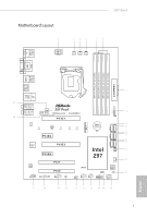
Z97 Pro4 CHA_FAN2 PCI Express 3.0 PCIE_PWR1 PCIE1 Front USB 3.0 NUT4 NUT3 NUT2 NUT1 PCIE2 M2_1 CMOS Battery SATA3_0 SATA3_1 SATA3_2 Super I/O PCIE3 PCIE4 AUDIO CODEC HD_AUDIO1 1 TPM1 1 PCI1 PCI2 COM1 1 CI1 1 Intel Z97 CHA_FAN1 RoHS CLRMOS1 1 USB_6_7 1 USB_4_5 1 64Mb BIOS - ASRock Z97 Pro4 | Quick Installation Guide - Page 4
CPU Fan Connector (CPU_FAN1) 4 CPU Fan Connector (CPU_FAN2) 5 2 x 240-pin DDR3 DIMM Slots (DDR3_A1, DDR3_B1) 6 2 x 240-pin DDR3 DIMM Slots (DDR3_A2, DDR3_B2) 7 ATX USB 2.0 Header (USB_4_5) 22 USB 2.0 Header (USB_6_7) 23 Clear CMOS Jumper (CLRCMOS1) 24 Chassis Intrusion Header (CI1) 25 COM Port Header - ASRock Z97 Pro4 | Quick Installation Guide - Page 5
I/O Panel 1 2 3 Z97 Pro4 57 4 68 15 14 No. Description 1 USB 2.0 Ports (USB01) 2 D-Sub Port 3 USB 3.0 Ports (USB3_0_1) 4 LAN RJ-45 Port* 5 Central / Bass (Orange) 6 Rear Speaker (Black) 7 Line - ASRock Z97 Pro4 | Quick Installation Guide - Page 6
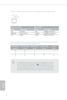
* There are two LEDs on each LAN port. Please refer to the table below for the LAN port LED indications. ACT/LINK LED SPEED LED LAN Port Activity / Link LED Status Description Off Blinking On No Link Data Activity Link Speed LED Status Off Orange Green Description 10Mbps connection 100Mbps - ASRock Z97 Pro4 | Quick Installation Guide - Page 7
. You may find the latest VGA cards and CPU support list on ASRock's website as well. ASRock website http://www.asrock.com. 1.1 Package Contents • ASRock Z97 Pro4 Motherboard (ATX Form Factor) • ASRock Z97 Pro4 Quick Installation Guide • ASRock Z97 Pro4 Support CD • 2 x Serial ATA (SATA) Data Cables - ASRock Z97 Pro4 | Quick Installation Guide - Page 8
ASRock APP Shop • Supports 4th Gen & 5th Generation Intel® Coreth Processors (Socket 1150) • Digi Power design • 6 Power Phase design • Supports Intel® Turbo Boost 2.0 Technology • Supports Intel® K-Series unlocked CPUs • Supports ASRock BCLK Full-range Overclocking Chipset • Intel® Z97 Memory - ASRock Z97 Pro4 | Quick Installation Guide - Page 9
Z97 Pro4 Graphics Audio LAN • Intel® HD Graphics Built-in Visuals and the VGA outputs can be supported only with processors which are GPU integrated. • Supports Intel® HD Graphics Built-in Visuals : Intel® Quick Sync Video with AVC, MVC (S3D) and MPEG-2 Full HW Encode1, Intel® InTruTM 3D, Intel® - ASRock Z97 Pro4 | Quick Installation Guide - Page 10
Power Fan Connector (3-pin) • 1 x 24 pin ATX Power Connector • 1 x 8 pin 12V Power Connector • 1 x PCIe Power Connector • 1 x Front Panel Audio Connector • 1 x Thunderbolt AIC Connector • 2 x USB 2.0 Headers (Support 4 USB 2.0 ports) (Supports ESD Protection (ASRock Full Spike Protection)) • 1 x USB - ASRock Z97 Pro4 | Quick Installation Guide - Page 11
Z97 Pro4 BIOS Feature Support CD Hardware Monitor OS Certifications • 64Mb AMI UEFI Legal BIOS with multilingual GUI support • ACPI 1.1 Compliant wake up events • SMBIOS 2.3.1 support • CPU, DRAM, PCH 1.05V, PCH 1.5V Voltage Multi-adjust- ment • Drivers, Utilities, AntiVirus Software (Trial - ASRock Z97 Pro4 | Quick Installation Guide - Page 12
for your convenience. We provide various apps and support software for users to download on the mainpage of APP Shop. You can easily optimize your system and keep your motherboard up to date with a few clicks. ASRock A-Tuning A-Tuning is ASRock's multi purpose software suite with a new interface - ASRock Z97 Pro4 | Quick Installation Guide - Page 13
Z97 Pro4 ASRock APP Charger Simply by installing the ASRock APP Charger makes your iPhone/iPad/iPod Touch charge up to 40% faster than before on your computer. ASRock APP Charger allows you to quickly charge many Apple devices simultaneously and even supports continuous charging when your PC enters - ASRock Z97 Pro4 | Quick Installation Guide - Page 14
loss occurs during the BIOS updating process, ASRock Crashless BIOS will automatically finish the BIOS update procedure after regaining power. Please note that BIOS files need to be placed in the root directory of your USB disk. Only USB 2.0 ports support this feature. ASRock OMG (Online Management - ASRock Z97 Pro4 | Quick Installation Guide - Page 15
Z97 Pro4 ASRock Dehumidifier Function Users may prevent motherboard damages due to dampness by enabling "Dehumidifier Function". When enabling Dehumidifier Function, the computer will power on automatically to dehumidify the system after entering S4/S5 state. ASRock Easy RAID Installer ASRock Easy - ASRock Z97 Pro4 | Quick Installation Guide - Page 16
is an ATX form factor motherboard. Before you install the motherboard, study the configuration of your chassis to ensure that the motherboard fits into it. Pre-installation Precautions Take note of the following precautions before you install motherboard components or change any motherboard settings - ASRock Z97 Pro4 | Quick Installation Guide - Page 17
Z97 Pro4 2.1 Installing the CPU 1. Before you insert the 1150-Pin CPU into the socket, please check if the PnP cap is on the socket, if the CPU surface is unclean, or if there are any bent pins in the socket. Do not force to insert the CPU into the socket if above situation is found. Otherwise, the - ASRock Z97 Pro4 | Quick Installation Guide - Page 18
4 5 16 3 English - ASRock Z97 Pro4 | Quick Installation Guide - Page 19
Z97 Pro4 Please save and replace the cover if the processor is removed. The cover must be placed if you wish to return the motherboard for after service. 17 English - ASRock Z97 Pro4 | Quick Installation Guide - Page 20
2.2 Installing the CPU Fan and Heatsink 1 2 CPU_FAN English 18 - ASRock Z97 Pro4 | Quick Installation Guide - Page 21
Z97 Pro4 2.3 Installing Memory Modules (DIMM) This motherboard provides four 240-pin DDR3 (Double Data Rate 3) DIMM slots, and supports Dual Channel Memory Technology. 1. For dual channel configuration, you always need to install identical (the same brand, speed, size and chip-type) DDR3 DIMM - ASRock Z97 Pro4 | Quick Installation Guide - Page 22
1 2 3 20 English - ASRock Z97 Pro4 | Quick Installation Guide - Page 23
Z97 Pro4 2.4 Expansion Slots (PCI and PCI Express Slots) There are 2 PCI slots and 4 PCI Express slots on the motherboard. Before installing an expansion card, please make sure that the power supply is switched off or the power cord is unplugged. Please read the documentation of the - ASRock Z97 Pro4 | Quick Installation Guide - Page 24
. Clear CMOS Jumper (CLRCMOS1) (see p.1, No. 23) Default Clear CMOS CLRCMOS1 allows you to clear the data in CMOS. To clear and reset the system do not clear the CMOS right after you update the BIOS. If you need to clear the CMOS when you just finish updating the BIOS, you must boot up the system - ASRock Z97 Pro4 | Quick Installation Guide - Page 25
Z97 Pro4 2.6 Onboard Headers and Connectors Onboard headers and connectors are NOT jumpers. Do NOT place jumper caps over these headers and connectors. Placing jumper caps over the headers and connectors will cause permanent damage to the motherboard of power switch, reset switch, power LED, - ASRock Z97 Pro4 | Quick Installation Guide - Page 26
see p.1, No. 14) SATA3_2 SATA3_1 SATA3_0 SATA3_5 SATA3_4 SATA3_3 These six SATA3 connectors support SATA data cables for internal storage devices with up to 6.0 Gb/s data transfer rate the I/O panel, there are two headers on this motherboard. Each USB 2.0 header can support two ports. English 24 - ASRock Z97 Pro4 | Quick Installation Guide - Page 27
Z97 Pro4 USB 3.0 Header there is one header on this motherboard. Each USB 3.0 header can support two ports. Front Panel Audio supports Jack Sensing, but the panel wire on the chassis must support HDA to function correctly. Please follow the instructions in our manual and chassis manual to install - ASRock Z97 Pro4 | Quick Installation Guide - Page 28
Fan) connector. If you plan to connect a 3-Pin CPU fan, please connect it to Pin 1-3. 12 24 1 13 This motherboard provides a 24-pin ATX power connector. To use a 20-pin ATX power supply, please plug it along Pin 1 and Pin 13. ATX 12V Power Connector (8-pin ATX12V1) (see p.1, No. 1) 8 5 This - ASRock Z97 Pro4 | Quick Installation Guide - Page 29
Z97 Pro4 Serial Port Header (9-pin COM1) (see p.1, No. 25) RRXD1 DDTR#1 DDSR#1 CCTS#1 1 RRI#1 RRTS#1 GND TTXD1 DDCD#1 This COM1 header supports a serial port module. GND LAD1_L LAD2_L SMB_DATA_MAIN SMB_CLK_MAIN GND This motherboard supports CASE OPEN detection feature that detects if the - ASRock Z97 Pro4 | Quick Installation Guide - Page 30
2.7 M.2_SSD (NGFF) Module Installation Guide The M.2, also known as the Next SATA Express connector to use. *The M.2_SSD (NGFF) Socket 3 supports SSD drives. Please note that the WiFi or other non-SSD M.2 modules are not supported. Installing the M.2_SSD (NGFF) Module Step 1 Prepare a M.2_SSD (NGFF - ASRock Z97 Pro4 | Quick Installation Guide - Page 31
B A C B A E D C B A E D NUT2 NUT1 Z97 Pro4 Step 3 Move the standoff based on the module type and length. The on the nut to be used. Hand tighten the standoff into the desired nut location on the motherboard. Step 5 Align and gently insert the M.2 (NGFF) SSD module into the M.2 slot. - ASRock Z97 Pro4 | Quick Installation Guide - Page 32
) ADATA AXNS381E-128GM-B ADATA AXNS381E-256GM-B Crucial CT120M500SSD4/120G Crucial CT240M500SSD4/240G Intel SSDSCKGW080A401/80G Kingston RBU-SNS8400S3/180GD For the latest updates of M.2_SSD (NFGG) module support list, please visit our website for details: http://www.asrock.com English 30 - ASRock Z97 Pro4 | Quick Installation Guide - Page 33
unterstützter VGA-Karten und Prozessoren auf der ASRock-Webseite: ASRock-Website http://www.asrock.com. 1.1 Lieferumfang • ASRock Z97 Pro4 - Motherboard (ATX-Formfaktor) • ASRock Z97 Pro4 - Schnellinstallationsanleitung • ASRock Z97 Pro4 - Support-CD • 2 x Serial-ATA- (SATA) Datenkabel (optional - ASRock Z97 Pro4 | Quick Installation Guide - Page 34
ützt Intel® CoreTM-Prozessoren (Sockel 1150) der 4ten & 5ten Generation • Digipower-Design • 6-Leistungsphasendesign • Unterstützt Intel® Turbo Boost 2.0-Technologie • Unterstützt CPUs mit freiem Multiplikator der Intel® K-Serie • Unterstützt ASRock BCLK-Übertaktung (voller Bereich) • Intel® Z97 - ASRock Z97 Pro4 | Quick Installation Guide - Page 35
der Fine Gold-Serie • Gigabit LAN 10/100/1000 Mb/s • Giga PHY Intel® I218V • Unterstützt Intel® Remote Wake Technology • Unterstützt Wake-On-LAN • Unterstützt Blitzschutz/Schutz gegen elektrostatische Entla- dung (ASRock Full Spike Protection) • Unterstützt energieeffizientes Ethernet 802.3az - ASRock Z97 Pro4 | Quick Installation Guide - Page 36
ASRock Full Spike Protection)) • 4 x USB 3.0-Ports (unterstützt Schutz gegen elektrostatische Entladung (ASRock Intel Rapid Storage Technology 13 und Intel Stiftleiste • 1 x Betrieb-LED-Stiftleiste • 2 x CPU-Lüfteranschlüsse (1 x 4-polig, 1 x 3-polig) • 1 x 24-poliger ATX-Netzanschluss • 1 x 8-poliger - ASRock Z97 Pro4 | Quick Installation Guide - Page 37
Z97 Pro4 BIOS-Funktion • 64-Mb-AMI-UEFI-Legal-BIOS mit Unterstützung mehrsprachiger grafischer Benutzerschnittstellen • ACPI 1.1-konforme Aufweckereignisse • SMBIOS 2.3.1-Unterstützung • CPU, DRAM, PCH 1,05 V, PCH 1,5 V / Mehrfachspannung- sanpassung Support-CD • Treiber, Dienstprogramme, - ASRock Z97 Pro4 | Quick Installation Guide - Page 38
ßen Sie dann Kontakt 2 und Kontakt 3 an CLRCMOS1 5 Sekunden lang mit einer Jumper-Kappe kurz. Löschen Sie den CMOS jedoch nicht direkt nach der BIOS-Aktualisierung. Falls Sie den CMOS direkt nach Abschluss der BIOSAktualisierung löschen müssen, starten Sie das System zunächst; fahren Sie es dann vor - ASRock Z97 Pro4 | Quick Installation Guide - Page 39
Z97 Pro4 1.4 Integrierte Stiftleisten und Anschlüsse Integrierte Stiftleisten und Anschlüsse sind KEINE Jumper. Bringen Sie KEINE JumperKappen an diesen Stiftleisten und Anschlüssen an. Durch Anbringen von Jumper-Kappen an diesen Stiftleisten und Anschlüssen können Sie das Motherboard , Reset-Taste - ASRock Z97 Pro4 | Quick Installation Guide - Page 40
. 21) (9-polig, USB_6_7) (siehe S. 1, Nr. 22) USB_PWR PP+ GND DUMMY 1 GND P+ PUSB_PWR Neben vier USB 2.0-Ports an der E/A-Blende befinden sich zwei Stiftleisten an diesem Motherboard. Jede USB 2.0-Stiftleiste kann zwei Ports unterstützen. Deutsch 38 - ASRock Z97 Pro4 | Quick Installation Guide - Page 41
Z97 Pro4 USB 3.0-Stiftleiste (19-polig, USB3_4_5) (siehe S. 1, Nr. 8) Vbus IntA_PA_SSRXIntA_PA_SSRX+ GND vier USB 3.0-Ports an der E/A-Blende befindet sich eine Stiftleiste an diesem Motherboard. Jede USB 3.0-Stiftleiste kann zwei Ports unterstützen. Audiostiftleiste (Frontblende) - ASRock Z97 Pro4 | Quick Installation Guide - Page 42
+12V FAN_SPEED FAN_SPEED_CONTROL GND FAN_VOLTAGE FAN_SPEED Dieses Motherboard bietet einen 4-poligen CPULüfteranschluss (lautloser Lüfter). Falls Sie einen 3-poligen CPU-Lüfter anschließen möchten, verbinden Sie ihn bitte mit Kontakt 1 bis 3. ATX-Netzanschluss (24-polig, ATXPWR1) (siehe S. 1, Nr - ASRock Z97 Pro4 | Quick Installation Guide - Page 43
Z97 Pro4 Serieller-Port-Stiftleiste (9-polig, COM1) (siehe S. 1, Nr. 25) RRXD1 DDTR#1 LAD3 +3V LAD0 +3VSB GND GND SMB_CLK_MAIN SMB_DATA_MAIN LAD2 LAD1 GND S_PWRDWN# SERIRQ# GND Dieses Motherboard unterstützt die Gehäuseoffen-Erkennung, die erkennt, wenn die Gehäuseabdeckung entfernt wurde. Diese - ASRock Z97 Pro4 | Quick Installation Guide - Page 44
est également disponible sur le site Internet de ASRock. Site Internet ASRock http://www.asrock.com. 1.1 Contenu de l'emballage • Carte mère ASRock Z97 Pro4 (facteur de forme ATX) • Guide d'installation rapide ASRock Z97 Pro4 • CD d'assistance ASRock Z97 Pro4 • 2 x câbles de données Serial ATA (SATA - ASRock Z97 Pro4 | Quick Installation Guide - Page 45
4e et 5e génération Intel® CoreTM (socket 1150) • Conception Digi Power • Alimentation à 6 phases • Prend en charge la technologie Intel® Turbo Boost 2.0 • Prend en charge les processeurs débloqués de la série K Intel® • Prend en charge l'overclocking ASRock BCLK Full-range • Intel® Z97 Mémoire - ASRock Z97 Pro4 | Quick Installation Guide - Page 46
protection du contenu (codec audio Realtek ALC892) • Compatible audio Blu-ray Premium • Protection contre les surtensions (Protection complète contre les pics ASRock) • Couvercles audio série en or fin Nichicon • Gigabit LAN 10/100/1000 Mb/s • Giga PHY Intel® I218V • Prend en charge la technologie - ASRock Z97 Pro4 | Quick Installation Guide - Page 47
Z97 Pro4 Connectique du panneau arrière Stockage Connectique • 1 x port souris/clavier PS/2 • 1 x port D-Sub • 1 x port DVI-D • 1 x port HDMI • 1 x port sortie optique SPDIF • 4 x ports USB 2.0 (Protection contre les décharges élec- trostatiques (Protection complète contre les pics ASRock)) • 4 x - ASRock Z97 Pro4 | Quick Installation Guide - Page 48
, veuillez visiter notre site : http://www.asrock.com Il est important de signaler que l'overcloking présente certains risques, incluant des modifications du BIOS, l'application d'une technologie d'overclocking déliée et l'utilisation d'outils d'overclocking développés par des tiers. La stabilit - ASRock Z97 Pro4 | Quick Installation Guide - Page 49
Z97 Pro4 1.3 Configuration des cavaliers (jumpers) L'illustration ci-dessous vous renseigne sur la configuration des cavaliers (jumpers). Lorsque le capuchon du cavalier est installé sur les broches, le cavalier est « courtcircuité ». Si le capuchon du cavalier n'est pas installé sur les broches, le - ASRock Z97 Pro4 | Quick Installation Guide - Page 50
panneau frontal du châssis. Vous pouvez configurer la façon dont votre système doit s'arrêter à l'aide du bouton de mise en marche. RESET (bouton de réinitiélisation): pour brancher le bouton de réinitialisation du panneau frontal du châssis. Appuyez sur le bouton de réinitialisation pour redémarrer - ASRock Z97 Pro4 | Quick Installation Guide - Page 51
Z97 Pro4 Embase LED d'alimentation (PLED1 à 3 broches) (voir p.1, No. 17) 1 PLED- PLED+ PLED+ Connecteurs Serial ATA3 ( embase pour indiquer l'état d'alimentation du système. Ces six connecteurs SATA3 sont compatibles avec les câbles de données SATA pour les appareils de stockage internes avec - ASRock Z97 Pro4 | Quick Installation Guide - Page 52
(détection de la fiche), mais le panneau grillagé du châssis doit être compatible avec la HDA pour fonctionner correctement. Veuillez suivre les instructions figurant dans notre manuel et dans le manuel du châssis pour installer votre système. 2. Si vous utilisez un panneau audio AC'97, veuillez le - ASRock Z97 Pro4 | Quick Installation Guide - Page 53
Z97 Pro4 (PWR_FAN1 à 3 broches) (voir p.1, No. 2) Connecteurs du ventilateur du processeur (CPU_FAN1 à 4 broches) (voir p.1, No. 3) (CPU_FAN2 à 3 broches) (voir p.1, No. 4) Connecteur d'alimentation ATX lorsque plus de trois cartes graphiques sont installées. Thunderbolt AIC Connectique (TB1 à - ASRock Z97 Pro4 | Quick Installation Guide - Page 54
Embase pour port série (COM1 à 9 broches) (voir p.1, No. 25) RRXD1 DDTR#1 DDSR#1 CCTS#1 1 RRI#1 RRTS#1 GND TTXD1 DDCD#1 Cette embase COM1 prend en charge un module de port série. Embase d'intrusion châssis (CI1 à 2 broches) (voir p.1, No. 24) 1 GND Signal Embase TPM (TPMS1 à 17 broches) (voir - ASRock Z97 Pro4 | Quick Installation Guide - Page 55
più recenti e di supporto di CPU anche sul sito Web di ASRock. Sito Web di ASRock http://www.asrock.com. 1.1 Contenuto della confezione • Scheda madre ASRock Z97 Pro4 (Form Factor ATX) • Guida all'installazione rapida di ASRock Z97 Pro4 • CD di supporto di ASRock Z97 Pro4 • 2 x cavi dati Serial ATA - ASRock Z97 Pro4 | Quick Installation Guide - Page 56
Intel® CoreTM (Socket 1150) • Design Digi Power • Potenza a 6 fasi • Supporta la tecnologia Intel® Turbo Boost 2.0 • Supporto di CPU unlocked Intel® K-Series • Supporta gamma completa overclocking BCLK ASRock Chipset • Intel® Z97 ATTENZIONE) • Supporta Intel® Extreme Memory Profile (XMP)1.3/1.2 - ASRock Z97 Pro4 | Quick Installation Guide - Page 57
Z97 Pro4 Grafica Audio LAN • La videografica integrata della scheda video HD Intel® e le uscite VGA possono essere supportate soltanto con processori con GPU integrata. • Supporta la videografica integrata della scheda video HD Intel®: Intel® Quick Sync Video con AVC, MVC (S3D) e MPEG-2 Full HW - ASRock Z97 Pro4 | Quick Installation Guide - Page 58
10, Intel Rapid Storage Technology 13 e Intel Smart Response 1 collettore LED alimentatore • 2 connettori ventola CPU (1 x 4 pin, 1 x 3 pin) ventola alimentazione (3 pin) • 1 connettore alimentazione ATX 24 pin • 1 x Connettore alimentazione 12V ESD) (protezione completa ASRock dai picchi di corrente - ASRock Z97 Pro4 | Quick Installation Guide - Page 59
Z97 Pro4 Funzione BIOS • AMI UEFI Legal BIOS 64Mb con interfaccia di supporto multilingue • Eventi di riattivazione conformi a ACPI 1.1 • Supporto di SMBIOS 2.3.1 • Multiregolazione tensione CPU, DRAM, PCH 1,05 V, PCH 1,5 V CD di supporto • Driver, utilità, software antivirus (versione di prova - ASRock Z97 Pro4 | Quick Installation Guide - Page 60
jumper per cortocircuitare il pin2 e il pin3 su CLRCMOS1 per 5 secondi. Tuttavia, non azzerare la CMOS subito dopo aver aggiornato il BIOS. Se è necessario azzerare la CMOS dopo l'aggiornamento del BIOS, è necessario riavviare prima il sistema e in seguito spegnerlo prima di eseguire l'operazione di - ASRock Z97 Pro4 | Quick Installation Guide - Page 61
Z97 Pro4 1.4 Header e connettori sulla scheda Gli header e i connettori sulla scheda NON sono jumper. . Un modulo di pannello anteriore è composto principalmente da interruttore di alimentazione, interruttore di reset, LED di alimentazione, LED di attività disco rigido, altoparlante, ecc. Quando si - ASRock Z97 Pro4 | Quick Installation Guide - Page 62
Header LED di alimentazione (PLED1 a 3 pin) (vedere pag. 1, n. 17) Connettori Serial ATA3 (SATA3_0: vedere pag.1, n. 9) (SATA3_1: vedere pag. 1, n. 11) (SATA3_2: vedere pag. 1, n. 13) (SATA3_3: vedere pag.1, n. 10) (SATA3_4: vedere pag.1, n. 12) (SATA3_5: vedere pag.1, n. 14) SATA3_2 SATA3_1 - ASRock Z97 Pro4 | Quick Installation Guide - Page 63
Z97 Pro4 Header USB 3.0 (USB3_4_5 a 19 pin) (vedere pag. 1, n. 8) Vbus IntA_PA_SSRXIntA_PA_SSRX+ GND deve supportare HDA per funzionare correttamente. Seguire le istruzioni presenti nel nostro manuale e nel manuale dello chassis per installare il sistema. 2. Se si utilizza un pannello - ASRock Z97 Pro4 | Quick Installation Guide - Page 64
8 pin. Per utilizzare un'alimentazione ATX a 4 pin, collegarla lungo il pin1 e il pin 5. Connettore alimentazione PCIe (4-pin PCIE_PWR1) (vedere pag. 1, n. 28) GND +12V DETECT Collegare un cavo di alimentazione molex a 4 pin a questo connettore quando sono installate più di tre schede grafiche - ASRock Z97 Pro4 | Quick Installation Guide - Page 65
Z97 Pro4 Header porta seriale (COM1 a 9 pin) (vedere pag. 1, n. 25) RRXD1 DDTR#1 DDSR#1 CCTS#1 1 RRI#1 RRTS#1 GND TTXD1 DDCD#1 Questo header COM1 supporta un modulo di porta - ASRock Z97 Pro4 | Quick Installation Guide - Page 66
la lista de compatibilidad de la CPU, en el sitio web de ASRock. Sitio web de ASRock http://www.asrock.com. 1.1 Contenido del paquete • Placa base ASRock Z97 Pro4 (Factor de forma ATX) • Guía de instalación rápida de ASRock Z97 Pro4 • CD de soporte de ASRock Z97 Pro4 • 2 cables de datos Serie ATA - ASRock Z97 Pro4 | Quick Installation Guide - Page 67
Intel® CoreTM (Socket 1150) • Diseño Digi Power • Diseño de 6 fases de alimentación • Compatible con la tecnología de Intel® Turbo Boost 2.0 • Compatible con CPU serie K desbloqueada de Intel® • Compatible con overclocking de rango completo BCLK de ASRock Conjunto de chips • Intel® Z97 - ASRock Z97 Pro4 | Quick Installation Guide - Page 68
Fine Gold • LAN Gigabit 10/100/1000 Mb/s • Giga PHY Intel® I218V • Compatible con la Tecnología Remote Wake de Intel® • Compatible con Wake-On-LAN • Compatible con protección contra rayos y electricidad elec- trostática (protección ASRock Full Spike) • Compatible con Ethernet de consumo eficiente de - ASRock Z97 Pro4 | Quick Installation Guide - Page 69
Z97 Pro4 Panel trasero I/O • 1 puerto de ratón/teclado PS/2 • 1 puerto D-Sub • 1 puerto DVI-D • 1 puerto HDMI • 1 puerto de salida SPDIF óptica • 4 puertos USB 2.0 (compatible con protección contra electricidad estática (protección ASRock Full Spike)) • 4 puertos USB 3.0 (compatible con protección - ASRock Z97 Pro4 | Quick Installation Guide - Page 70
de alimentación compatible con ErP/EuP) * Para obtener más información acerca del producto, visite nuestro sitio web: http://www.asrock.com Tenga en cuenta que existen ciertos riesgos relacionados con el overclocking (sobreaceleración), incluyendo el ajuste de la configuración del BIOS, aplicando - ASRock Z97 Pro4 | Quick Installation Guide - Page 71
Z97 Pro4 1.3 Instalación de los puentes La instalación muestra cómo deben instalarse durante 5 segundos. Sin embargo, no borre el CMOS justo después de que haya actualizado el BIOS. Si necesita borrar el CMOS cuando acabe de actualizar el BIOS, deberá arrancar el sistema primero y, a continuación, - ASRock Z97 Pro4 | Quick Installation Guide - Page 72
alimentación del panel frontal del chasis. Deberá configurar la forma en la que su sistema se apagará mediante el interruptor de alimentación. RESET (Interruptor de reseteo): Conéctelo al interruptor de reseteo del panel frontal del chasis. Pulse el interruptor de reseteo para resetear el ordenador - ASRock Z97 Pro4 | Quick Installation Guide - Page 73
SATA3_2 SATA3_1 SATA3_0 SATA3_5 SATA3_4 SATA3_3 Español Z97 Pro4 Cabezal de indicador LED de alimentación (PLED1 de 3 pines) (consulte la pág.1, N.º estado de alimentación del sistema. Estos seis conectores SATA3 son compatibles con cables de datos SATA para dispositivos de almacenamiento interno - ASRock Z97 Pro4 | Quick Installation Guide - Page 74
el método de sensor de conectores, sin embargo, el cable del panel del chasis deberá ser compatible con HDA para que pueda funcionar correctamente. Siga las instrucciones que se indican en nuestro manual y en el manual del chasis para instalar su sistema. 2. Si utiliza un panel de audio AC'97, col - ASRock Z97 Pro4 | Quick Installation Guide - Page 75
Z97 Pro4 (PWR_FAN1 de 3 pines) (consulte la pág.1, N.º 2) Conectores del ventilador de la CPU (CPU_FAN1 de 4 pines) (consulte la pág.1, N.º 3) (CPU_FAN2 de 3 pines) (consulte la pág.1, N.º 4) Conector de alimentación ATX (ATXPWR1 de 24 pines) (consulte la pág.1, N.º 7) Conector de alimentación ATX - ASRock Z97 Pro4 | Quick Installation Guide - Page 76
ha retirado la cubierta del chasis. Esta función requiere un chasis diseñado para la detección de intrusión del chasis. Este conector es compatible con el sistema Módulo de Plataforma Segura (TPM, en inglés), que puede almacenar de forma segura claves, certificados digitales, contraseñas y datos. Un - ASRock Z97 Pro4 | Quick Installation Guide - Page 77
Z97 Pro4 1 ASRock Z97 Pro4 ASRock ASRock BIOS ASRock ASRock VGA ASRock http://www.asrock.com. 1.1 ASRock Z97 Pro4 ATX ASRock Z97 Pro4 ASRock Z97 Pro4 • 2 Serial ATA (SATA 1 1 x M.2_SSD (NGFF) Socket 3 75 - ASRock Z97 Pro4 | Quick Installation Guide - Page 78
Shop 4го и 5 Intel® CoreTM (Socket 1150) • Digi Power design 6 Intel® Turbo Boost 2.0 Intel K с ASRock BCLK Чипсет • Intel® Z97 Память DDR3 • 4 DDR3 DIMM DDR3 2933+(OC)/2800 (OC)/2400(OC)/2133(OC)/1866(OC)/1600/1333/1066 Non-ECC Unbuffered 32 Intel® Extreme Memory Profile (XMP - ASRock Z97 Pro4 | Quick Installation Guide - Page 79
Z97 Pro4 Intel® HD Graphics Built-in Visuals и VGA Intel® HD Graphics: Intel® Quick Sync Video с AVC, MVC (S3D) и MPEG-2 Full HW Encode1, Intel® InTruTM 3D, Intel® Clear Video HD Technology, Intel® InsiderTM, Intel® HD Graphics 4400/4600 • Pixel Shader 5.0, DirectX 11.1 1792 D-Sub, - ASRock Z97 Pro4 | Quick Installation Guide - Page 80
х 4 1 х 3 1 x (3 1 24 1 x 8 12 В • 1 x PCIe • 1 x 1 x AIC Thunderbolt • 2 x USB 2.0 (до 4 USB 2.0 ASRock Full Spike Protection) • 1 x USB 3.0 (до 2 USB 3.0 ASRock Full Spike Protection) BIOS 78 • AMI UEFI Legal BIOS 64 ACPI 1.1 SMBIOS 2.3.1 DRAM, PCH 1,05 В, PCH 1,5 В - ASRock Z97 Pro4 | Quick Installation Guide - Page 81
Z97 Pro4 Google Chrome, Start8 30 дней), Kloudian Orbweb.ME Professional (Win 8.1) 12 В, +5 В, +3,3 В, ЦП Vcore • Microsoft® Windows® 8.1 32-bit / 8.1 64-bit / 8 32-bit / 8 64-bit / 7 32-bit / 7 64-bit • FCC, CE, WHQL ErP/EuP ErP/EuP) http://www.asrock.com BIOS Untied Overclocking - ASRock Z97 Pro4 | Quick Installation Guide - Page 82
1.3 3 1 и 2 CMOS (CLRCMOS1 1, № 23) CMOS CLRCMOS1 CMOS 15 2 и 3 на CLRCMOS1 на 5 CMOS BIOS CMOS BIOS CMOS CMOS. 80 - ASRock Z97 Pro4 | Quick Installation Guide - Page 83
Z97 Pro4 1.4 9 PANEL1 1, № 18) PLED+ PLEDPWRBTN# GND 1 GND RESET# GND HDLEDHDLED+ PWRBTN RESET PLED S1/S3 S4 S5 HDLED 81 - ASRock Z97 Pro4 | Quick Installation Guide - Page 84
3 PLED1 1, № 17) 1 PLED- PLED+ PLED+ Serial ATA3 (SATA3_0 1, № 9) (SATA3_1 1, № 11) (SATA3_2 1, № 13) (SATA3_3 1, № 10) (SATA3_4 1, № 12) (SATA3_5 1, № 14) SATA3_2 SATA3_1 SATA3_0 SATA3_5 SATA3_4 SATA3_3 SATA3 SATA 6,0 Гб/с. SATA3_4, SATA3_5 SATA Express. SATA Express ( - ASRock Z97 Pro4 | Quick Installation Guide - Page 85
Z97 Pro4 USB 3.0 (19 USB3_4_5 1, № 8) Vbus IntA_PA_SSRXIntA_PA_SSRX+ GND IntA_PA_SSTXIntA_PA_SSTX+ GND IntA_PA_DIntA_PA_D+ Vbus IntA_PB_SSRXIntA_PB_SSRX+ GND IntA_PB_SSTXIntA_PB_SSTX+ GND IntA_PB_DIntA_PB_D+ Dummy 1 USB 3.0 USB 3.0 9 HD_AUDIO1 1, № 27) GND PRESENCE# MIC_RET - ASRock Z97 Pro4 | Quick Installation Guide - Page 86
1, № 28) Thunderbolt AIC 5 TB1 1, № 20) 4 3 2 1 GND +12V FAN_SPEED FAN_SPEED_CONTROL GND FAN_VOLTAGE CHA_FAN_SPEED 12 24 1 13 4 3 1-3. 24 20 ATX 1 13. 8 5 8 4 1 12 4 ATX, 1 5. GND +12V DETECT 4 Molex. AIC ThunderboltTM 5 GPIO). 84 - ASRock Z97 Pro4 | Quick Installation Guide - Page 87
Z97 Pro4 9 COM1 1, № 25) RRXD1 DDTR#1 DDSR#1 CCTS#1 1 RRI#1 RRTS#1 GND TTXD1 DDCD#1 COM1 2 CI1 1, № 24) 1 GND Signal 17 TPMS1 1, № 26) 1 PCICLK FRAME PCIRST# LAD3 +3V LAD0 + - ASRock Z97 Pro4 | Quick Installation Guide - Page 88
a lista de placas VGA e CPU mais recentes suportadas no site da ASRock. Site da ASRock http://www.asrock.com. 1.1 Conteúdo da embalagem • Placa Mãe ASRock Z97 Pro4 (Fator de Forma ATX) • Guia de Instalação Rápida da ASRock Z97 Pro4 • CD de Suporte da ASRock Z97 Pro4 • 2 x Cabos de dados Serial - ASRock Z97 Pro4 | Quick Installation Guide - Page 89
ção de Processadores Intel® CoreTM (Soquete 1150) • Design Digi Power • Design com 6 fases de alimentação • Suporta a tecnologia Intel® Turbo Boost 2.0 • Suporta CPU desbloqueado da série K da Intel® • Suporta Overclocking total ASRock BCLK Português Chipset • Intel® Z97 Memória • Tecnologia - ASRock Z97 Pro4 | Quick Installation Guide - Page 90
), xvYCC e HBR (High Bit Rate Audio) com porta HDMI (É necessário um monitor compatível com HDMI) • Suporta HDCP com Portas DVI-D e HDMI • Suporta reprodução Full ASRock) • Capacitor de Áudio Série Ouro Fino Nichicon • LAN Gigabit a 10/100/1000 Mb/s • Giga PHY Intel® I218V • Suporta tecnologia Intel - ASRock Z97 Pro4 | Quick Installation Guide - Page 91
USB 3.0 (Suporta 2 portas USB 3.0) (Suporta Proteção ESD (Proteção Total Contra Picos ASRock)) Funções da BIOS • 64Mb AMI Legal UEFI BIOS com suporte multilingue GUI • ACPI 1.1 compatível com eventos de despertar • Suporta SMBIOS 2.3.1 • Multi-ajuste de tensão de CPU, DRAM, PCH 1,05V, PCH 1,5V 89 - ASRock Z97 Pro4 | Quick Installation Guide - Page 92
nosso site: http://www.asrock.com Por favor, observe que existe um certo risco envolvendo overclocking, incluindo o ajuste das definições na BIOS, a aplicação de tecnologia Untied Overclocking ou a utilização de ferramentas de overclocking de terceiros. O overclocking poderá afetar a estabilidade do - ASRock Z97 Pro4 | Quick Installation Guide - Page 93
Z97 Pro4 1.3 Configuração dos jumpers A imagem abaixo mostra como os jumpers são configurados. segundos. No entanto, não apague o CMOS logo após ter realizado a atualização da BIOS. Se você precisar apagar o CMOS logo após ter terminado uma atualização da BIOS, deverá primeiro iniciar o sistema - ASRock Z97 Pro4 | Quick Installation Guide - Page 94
de alimentação no painel frontal do chassi. Você pode configurar a forma para desligar o seu sistema através do botão de alimentação. RESET (Botão de reinicialização): Conecte o botão de reinicialização no painel frontal do chassi. Pressione o botão de reinicialização para reiniciar o computador, se - ASRock Z97 Pro4 | Quick Installation Guide - Page 95
SATA3_2 SATA3_1 SATA3_0 SATA3_5 SATA3_4 SATA3_3 Português Z97 Pro4 Suporte LED de alimentação (PLED1 de 3 pinos) (ver p.1, N.º 17) Conectores série ATA3 (SATA3_0: ver p.1, N.º 9) (SATA3_1: ver p.1, N.º 11) (SATA3_2: ver p.1, N.º 13) (SATA3_3: ver p.1, N.º 10) (SATA3_4: ver p.1, N.º - ASRock Z97 Pro4 | Quick Installation Guide - Page 96
no chassi deverá suportar HDA para funcionar corretamente. Por favor, siga as instruções no nosso manual e no manual do chassi para instalar o seu sistema. 2. Se utilizar um painel de áudio AC'97, instale-o no terminal de áudio do painel frontal de acordo com os passos abaixo: A. Ligue Mic_IN (MIC - ASRock Z97 Pro4 | Quick Installation Guide - Page 97
Z97 Pro4 Português (PWR_FAN1 de 3 pinos) (ver p.1, N.º 2) GND FAN_VOLTAGE FAN_SPEED Conectores do ventilador da CPU (CPU_FAN1 de 4 pinos) placa-mãe inclui um conector de alimentação de 12V ATX de 8 pinos. 1 Para utilizar uma fonte de alimentação ATX de 4 pinos, introduza-a no Pino 1 e Pino - ASRock Z97 Pro4 | Quick Installation Guide - Page 98
Suporte da porta serial (COM1 de 9 pinos) (ver p.1, N.º 25) RRXD1 DDTR#1 DDSR#1 CCTS#1 1 RRI#1 RRTS#1 GND TTXD1 DDCD#1 Este suporte COM1 recebe um módulo da porta serial. Suporte de intrusão do chassi (CI1 de 2 pinos) (ver p.1, N.º 24) 1 GND Signal Suporte TPM (TPMS1 de 17 pinos) (ver p.1, N.º - ASRock Z97 Pro4 | Quick Installation Guide - Page 99
edin. En güncel VGA kartları ve CPU destek listelerini de ASRock'ın web sitesinden bulabilirsiniz. ASRock web sitesi http://www.asrock.com. 1.1 Ambalaj İçeriği • ASRock Z97 Pro4 Anakartı (ATX Form Faktörü) • ASRock Z97 Pro4 Hızlı Kurulum Kılavuzu • ASRock Z97 Pro4 Destek CD'si • 2 x Seri ATA (SATA - ASRock Z97 Pro4 | Quick Installation Guide - Page 100
® CoreTM İşlemcileri (Yuva 1150) destekler • Dijital Güç tasarımı • 6 Güç Safhası tasarımı • Intel® Turbo Boost 2.0 Teknolojisini destekler • Intel® K Serisi kilitsiz işlemcileri destekler • ASRock BCLK tam aralıklı Hız Aşırtmayı destekler Türkçe Yonga kümesi • Intel® Z97 Bellek • Çift Kanall - ASRock Z97 Pro4 | Quick Installation Guide - Page 101
Koruması) • Nichicon Fine Gold Serisi Ses Kapakları • Gigabit LAN 10/100/1000 Mb/s • Giga PHY Intel® I218V • Intel® Uzaktan Uyandırma Teknolojisi • LAN Açılışını Destekler • Yıldırım/ESD Koruması Destekler (ASRock Tam Ani Gerilim Koruması) • Enerji Verimliliğine Sahip Ethernet 802.3az işlevini - ASRock Z97 Pro4 | Quick Installation Guide - Page 102
ASRock Tam Ani Gerilim Koruması)) • LED'e sahip 1 x RJ-45 LAN Bağlantı Noktası (ACT/LINK LED ve SPEED LED) • HD Ses Jakları: Arka Hoparlör / Merkezi / Bas / Hat Girişi / Ön Hoparlör / Mikrofon • 6 x SATA3 6,0 Gb/s Bağlayıcısı, RAID (RAID 0, RAID 1, RAID 5, RAID 10, Intel x 24 pim ATX Güç Bağlayıcısı - ASRock Z97 Pro4 | Quick Installation Guide - Page 103
Z97 Pro4 BIOS Özelliği Destek CD'si Donanım Monitörü OS Belgeler • Çok dilli GUI Desteği ile 64Mb AMI UEFI Legal BIOS • ACPI 1.1 Uyumlu uyandırma olayları • SMBIOS 2.3.1 desteği • CPU, DRAM, PCH Windows® tarafından kullanılmayan bellekten faydalanmak için ASRock XFast RAM'i kullanabilirsiniz. 101 - ASRock Z97 Pro4 | Quick Installation Guide - Page 104
boyunca kısaltmak için bir bağlantı teli kullanın. Ancak, CMOS'u lütfen BIOS'u güncelledikten hemen sonra temizlemeyin. BIOS'u güncelledikten hemen sonra CMOS'u temizlemeniz gerekirse, önce sistemi başlatın ve ardından CMOS temizleme işlemi öncesinde yeniden kapatın. Lütfen, parola, tarih, saat - ASRock Z97 Pro4 | Quick Installation Guide - Page 105
Z97 Pro4 1.4 Ekli Bağlantılar ve Bağlayıcılar Ekli bağlantılar ve bağlayıcılar . Sistem Paneli Bağlantısı (9-pin PANEL1) (bkz sf.1, No. 18) PLED+ PLEDPWRBTN# GND 1 GND RESET# GND HDLEDHDLED+ Güç anahtarını bağlayın, kasa üzerindeki anahtar ile sistem durumu belirtecini aşağıdaki pim düzenine göre - ASRock Z97 Pro4 | Quick Installation Guide - Page 106
Türkçe Güç LED Bağlantısı (3-pin PLED1) (bkz. sf.1, No. 17) Seri ATA3 Bağlayıcıları (SATA3_0: bkz. sf.1, No. 9) (SATA3_1: bkz. sf.1, No. 11) (SATA3_2: bkz. sf.1, No. 13) (SATA3_3: bkz. sf.1, No. 10) (SATA3_4: bkz. sf.1, No. 12) (SATA3_5: bkz. sf.1, No. 14) Seri ATA Express Bağlayıcısı (SATAE_1: bkz - ASRock Z97 Pro4 | Quick Installation Guide - Page 107
Z97 Pro4 Türkçe USB 3.0 Bağlantı (19-pin USB3_4_5) (bkz. sf.1, No. 8) Vbus IntA_PA_SSRXIntA_PA_SSRX+ GND IntA_PA_SSTXIntA_PA_SSTX+ GND IntA_PA_DIntA_PA_D+ Vbus IntA_PB_SSRXIntA_PB_SSRX+ GND IntA_PB_SSTXIntA_PB_SSTX+ GND IntA_PB_DIntA_PB_D+ Dummy 1 Bu anakart ü - ASRock Z97 Pro4 | Quick Installation Guide - Page 108
GND FAN_VOLTAGE CHA_FAN_SPEED 12 24 1 13 Bu anakart, 4-Pin CPU fan (Sessiz Fan) bağlayıcısı sağlamaktadır. 3-Pin CPU fan bağlamak istiyorsanız, lütfen Pin 1-3'ü kullanın. Bu anakart, 24-pin ATX güç bağlayıcısı sağlamaktadır. 20-pin ATX güç beslemesi kullanmak için, lütfen Pin 1 ve Pin 13'e ba - ASRock Z97 Pro4 | Quick Installation Guide - Page 109
Z97 Pro4 Seri Bağlantı Noktası Bağlantısı (9-pin COM1) (bkz. sf.1, No. 25) Kasa Yetkisiz Erişim Bağlantısı (2-pin CI1) (bkz. sf.1, No. 24) TPM - ASRock Z97 Pro4 | Quick Installation Guide - Page 110
한 국 어 1 개요 ASRock Z97 Pro4 ASRock ASRock BIOS ASRock ASRock VGA 카드와 CPU ASRock http://www.asrock.com. 1.1 • ASRock Z97 Pro4 ATX ASRock Z97 Pro4 ASRock Z97 Pro4 지원 CD ATA (SATA 2 I/O 1 개 • M.2_SSD (NGFF) 소켓 3 용 나사 1 개 108 - ASRock Z97 Pro4 | Quick Installation Guide - Page 111
Z97 Pro4 1.2 규격 CPU • ATX PCB ASRock 손실 70 NexFETTM MOSFET • 12K 100 PCB ASRock ASRock Cloud ASRock 앱 숍 • 4 세대 및 5 세대 Intel® CoreTM 1150) • Digi 6 Intel® Turbo Boost 2.0 Intel®K CPU 지원 • ASRock BCLK 한국어 칩세트 • Intel® Z97 메모리 DDR3 DDR3 DIMM 슬롯 4 개 • DDR3 2933+(OC)/2800(OC)/ - ASRock Z97 Pro4 | Quick Installation Guide - Page 112
), xvYCC 및 HBR (High Bit Rate Audio)(HDMI HDMI DVI-D 및 HDMI HDCP 지원 • DVI-D 및 HDMI Full HD 1080p Blu-ray (BD 7.1 CH HD Realtek ALC892 Blu-ray ASRock Nichicon Fine Gold • Gigabit LAN 10/100/1000 Mb/s • Giga PHY Intel® I218V • Intel Wake-On-LAN ESD ASRock 802.3az 지원 • PXE 지원 110 - ASRock Z97 Pro4 | Quick Installation Guide - Page 113
Z97 Pro4 한국어 I/O • PS 1 2 개 • D-Sub 포트 1 개 • DVI-D 포트 1 개 • HDMI 포트 1 SPDIF 1 개 • USB 2.0 포트 4 개 (ESD ASRock 호 )) • USB 3.0 포트 4 개 (ESD ASRock 호 )) • LED 장착 RJ-45 LAN 포트 1 개 (ACT/LINK LED 및 SPEED LED) • HD • SATA3 6.0 Gb/s 커넥터 6 개가 RAID (RAID 0, RAID 1, RAID 5, RAID 10, Intel - ASRock Z97 Pro4 | Quick Installation Guide - Page 114
• CPU CPU CPU CPU CPU 12V, +5V, +3.3V, CPU Vcore • Microsoft® Windows® 8.1 32 비트 / 8.1 64 비트 / 8 32 비트 / 8 64 비트 / 7 32 비트 / 7 64 비트 • FCC, CE, WHQL • ErP/EuP ErP/EuP http://www.asrock.com BIOS Untied Overclocking Technology 112 Windows® 32 4GB Windows® 64 ASRock XFast RAM - ASRock Z97 Pro4 | Quick Installation Guide - Page 115
Z97 Pro4 1.3 3 1 과 핀 2 Clear CMOS 점퍼 (CLRCMOS1) (1 23 기본값 Clear CMOS CLRCMOS1 CMOS 15 CLRCMOS1 의 핀 2 와 핀 3 을 5 BIOS CMOS BIOS CMOS CMOS CMOS 한국어 113 - ASRock Z97 Pro4 | Quick Installation Guide - Page 116
한 국 어 1.4 9 핀 PANEL1) (1 18 PLED+ PLEDPWRBTN# GND 1 GND RESET# GND HDLEDHDLED+ PWRBTN RESET PLED LED LED S1/S3 LED S4 S5 LED HDLED LED LED LED LED LED 114 - ASRock Z97 Pro4 | Quick Installation Guide - Page 117
SATA3_2 SATA3_1 SATA3_0 SATA3_5 SATA3_4 SATA3_3 한국어 Z97 Pro4 전원 LED 헤더 (3 핀 PLED1) (1 17 1 PLED- PLED+ PLED+ 시리얼 ATA3 커넥터 (SATA3_0: 1 9 SATA3_1: (1 11 SATA3_2: (1 13 SATA3_3: 1 10 SATA3_4: 1 12 SATA3_5: 1 14 SATA Express 커넥터 (SATAE_1: 1 15 LED 이들 6 개의 SATA3 6.0 Gb/ s - ASRock Z97 Pro4 | Quick Installation Guide - Page 118
USB 3.0 헤더 (19 핀 USB3_4_5) (1 8 Vbus IntA_PA_SSRXIntA_PA_SSRX+ GND IntA_PA_SSTXIntA_PA_SSTX+ GND IntA_PA_DIntA_PA_D+ Vbus IntA_PB_SSRXIntA_PB_SSRX+ GND IntA_PB_SSTXIntA_PB_SSTX+ GND IntA_PB_DIntA_PB_D+ Dummy 1 I/O 패널에 USB 3.0 USB 3.0 9 핀 HD_AUDIO1) (1 27 GND PRESENCE# MIC_RET OUT_RET - ASRock Z97 Pro4 | Quick Installation Guide - Page 119
Z97 Pro4 한국어 (3 핀 PWR_FAN1) (1 2 CPU 4 핀 CPU_FAN1) (1 3 (3 핀 CPU_FAN2) (1 4 4 3 2 1 GND +12V FAN_SPEED FAN_SPEED_CONTROL GND FAN_VOLTAGE CHA_FAN_SPEED 4 핀 CPU 습니다 . 3 핀 CPU 1-3 ATX 24 핀 ATXPWR1) (1 7 12 24 1 13 24 핀 ATX 20 핀 ATX 1 과 핀 13 ATX 12V 8 (8 핀 - ASRock Z97 Pro4 | Quick Installation Guide - Page 120
9 핀 COM1) (1 25 RRXD1 DDTR#1 DDSR#1 CCTS#1 1 RRI#1 RRTS#1 GND TTXD1 DDCD#1 2 핀 CI1) (1 24 1 GND Signal TPM 헤더 (17 핀 TPMS1) (1 26 1 PCICLK FRAME PCIRST# LAD3 +3V LAD0 +3VSB GND GND SMB_CLK_MAIN SMB_DATA_MAIN LAD2 LAD1 GND S_PWRDWN# SERIRQ# GND 이 COM1 TPM(Trusted Platform - ASRock Z97 Pro4 | Quick Installation Guide - Page 121
日本語 Z97 Pro4 1 ͡Ίʹ ASRock Z97 Pro4 ASRock Z97 Pro4 ASRock BIOS VGA CPU http://www.asrock.com. 1.1 • ASRock Z97 Pro4 ATX ASRock Z97 Pro4 ASRock Z97 Pro4 αϙʔτ CD • 2 x γϦΞϧ ATAʢSATA 1 x I/O 1 x M.2_SSD (NGFF) ιέοτ 3 ༻Ͷ͡ 119 - ASRock Z97 Pro4 | Quick Installation Guide - Page 122
1.2 仕様 • ATX PCB CPU ASRock 70 NexFETTM MOSFET • 12K 100 PCB ASRock ASRock Cloud ASRock APP γϣοϓ • ୈ 4 5 ੈ Intel® CoreTM 1150ʣ 6 Intel 2.0 Intel® K CPU ASRock BCLK 日本語 νοϓηοτ • Intel® Z97 ϝϞϦ DDR3 4 x DDR3 DIMM DDR3 2933+(OC)/2800(OC)/2400(OC)/2133(OC)/ 1866 - ASRock Z97 Pro4 | Quick Installation Guide - Page 123
Z97 Pro4 ΦʔσΟΦ LAN • Intel®HD VGA ग़ ྗɺGPU • Intel®HD AVCɺMVC (S3D)ɺMPEG-2 ϑϧ HW Τϯίʔυ 1 ͷ Intel® Quick Sync VideoɺIntel® InTruTM 3DɺIntel HD Intel TMɺIntel • 7.1 CH HD Realtek ALC892 ASRock ϯα LAN 10/100/1000 Mb PHY Intel® I218V • Intel ESD ASRock 802.3az Λαϙʔ τ • PXE - ASRock Z97 Pro4 | Quick Installation Guide - Page 124
Gb/s ίωΫλɺRAIDʢRAID 0ɺRAID 1ɺ RAID 5ɺRAID 10ɺIntel 13 ͓Αͼ Intel NCQɺAHCI • 1 x SATA Express ίωΫλʢSATA3_4ɺSATA3_5ɺ͓Αͼɺ CPU 1 x 4 ϐϯɺ1 x 3 ϐϯʣ • 2 x 1 x 4 ϐϯɺ1 x 3 ϐϯʣ • 1 x 3 ϐϯʣ • 1 x 24 ϐϯ ATX 1 x 8 ϐϯ 12V 1 x PCIe 1 x 1 x Thunderbolt AIC 2 x USB 2.0 ϔομʔʢ4 ݸͷ USB 2.0 ESD ASRock - ASRock Z97 Pro4 | Quick Installation Guide - Page 125
Z97 Pro4 日本語 BIOS CD OS ೝূ • 64Mb AMI UEFI Legal BIOS GUI ACPI 1.1 SMBIOS 2.3.1 CPUɺDRAMɺPCH 1.05VɺPCH 1.5V Google Chrome Startʢ8 30 Kloudian Orbweb.ME Professional (Win 8.1) • CPU CPU CPU CPU CPU 12Vɺ+5Vɺ+3.3VɺCPU Vcore • Microsoft® Windows® 8.1 32-bit / 8.1 64-bit / 8 32- - ASRock Z97 Pro4 | Quick Installation Guide - Page 126
日本語 1.3 3 1 ͱϐϯ 2 CMOS CLRCMOS1) ʢp.1ɺNo. 23 ࢀরʣ σϑΥϧτ CMOS ͷ ΫϦΞ CLRCMOS1 ɺCMOS 15 CLRCMOS1 ͷϐ ϯ 2 ͱϐϯ 3 5 BIOS CMOS BIOS CMOS CMOS CMOS 124 - ASRock Z97 Pro4 | Quick Installation Guide - Page 127
日本語 Z97 Pro4 1.4 9 ϐϯύωϧ 1ʣ ʢp.1ɺNo. 18 ࢀরʣ PLED+ PLEDPWRBTN# GND 1 GND RESET# GND HDLEDHDLED+ PWRBTN RESET PLED LED LED S1/S3 LED S4 S5 LED HDLED LED LED LED LED LED 125 - ASRock Z97 Pro4 | Quick Installation Guide - Page 128
日本語 ి ݯLED ϔομʔ ʢ3 ϐϯ PLED1ʣ ʢp.1ɺNo. 17 ࢀরʣ γϦΞϧ ATA3 SATA3_0ɿ p.1ɺNo. 9 ࢀরʣ (SATA3_1: p.1ɺNo. 11 ࢀরʣ ʢSATA3_2ɿ p.1ɺNo. 13 ࢀরʣ ʢSATA3_3ɿ p.1ɺNo. 10 ࢀরʣ ʢSATA3_4ɿ p.1ɺNo. 12 ࢀরʣ ʢSATA3_5ɿ p.1ɺNo. 14 ࢀরʣ γϦΞϧ ATA Express ί ωΫλ (SATAE_1: p.1ɺNo. 15 ࢀরʣ USB 2.0 ϔομʔ (9 ϐϯ USB_4_5) ʢp.1ɺNo. 21 ࢀরʣ - ASRock Z97 Pro4 | Quick Installation Guide - Page 129
Z97 Pro4 日本語 USB 3.0 ϔομʔ ʢ19 ϐϯ USB3_4_5ʣ ʢp.1ɺNo. 8 ࢀরʣ Vbus IntA_PA_SSRXIntA_PA_SSRX+ GND IntA_PA_SSTXIntA_PA_SSTX+ GND IntA_PA_DIntA_PA_D+ Vbus IntA_PB_SSRXIntA_PB_SSRX+ GND IntA_PB_SSTXIntA_PB_SSTX+ GND IntA_PB_DIntA_PB_D+ Dummy 1 I/O ύωϧͷ 4 ͭͷ USB 3.0 1 USB 3.0 2 9 ϐϯ HD_AUDIO1ʣ - ASRock Z97 Pro4 | Quick Installation Guide - Page 130
No. 20 ࢀরʣ 128 4 3 2 1 GND +12V FAN_SPEED FAN_SPEED_CONTROL GND FAN_VOLTAGE CHA_FAN_SPEED 12 24 1 13 4 ϐ ϯ CPU 3 ϐϯͷ CPU 1-3 24 ϐ ϯ ATX 20 ϐϯͷ ATX 1 ͱ 13 8 5 8 ϐ ϯ ATX 12V 4 1 4 ϐϯ ͷ ATX ʹɺϐϯ 1 ͱ 5 ൪ʹ߹ GND +12V DETECT 4 4 ThunderboltTM AIC 5 GPIO - ASRock Z97 Pro4 | Quick Installation Guide - Page 131
Z97 Pro4 9 ϐϯ COM1ʣ ʢp.1ɺNo. 25 ࢀরʣ RRXD1 DDTR#1 DDSR#1 CCTS#1 1 RRI#1 RRTS#1 GND TTXD1 DDCD#1 ͜ͷ COM1 2 ϐϯ CI1ʣ ʢp.1ɺNo. 24 ࢀরʣ 1 GND Signal TPM ϔομʔ ʢ17 ϐϯ TPMS1ʣ ʢp.1ɺNo. 26 ࢀরʣ 1 PCICLK FRAME - ASRock Z97 Pro4 | Quick Installation Guide - Page 132
1 简介 Z97 Pro4 BIOS VGA 卡和 CPU http://www.asrock.com。 1.1 • 华擎 Z97 Pro4 主板(ATX Z97 Pro4 Z97 Pro4 2 x 串行 ATA (SATA 1 x I/O 面板 • 1 x M.2_SSD (NGFF) 插座 3 使用) 130 - ASRock Z97 Pro4 | Quick Installation Guide - Page 133
Z97 Pro4 1.2 规格 CPU 扩充槽 • ATX 70 MOS • 12K 100 PCB 4 代和第 5 代 Intel® CoreTM 1150 6 CPU Intel® Turbo Boost 2.0 Intel® K CPU BCLK • Intel® Z97 DDR3 4 x DDR3 DIMM DDR3 2933+(OC)/2800(OC)/2400(OC)/2133(OC)/1866 (OC)/1600/1333/1066 非 ECC 32GB Intel® Extreme Memory - ASRock Z97 Pro4 | Quick Installation Guide - Page 134
、Deep Color (12bpc), xvYCC 和 HBR DVI-D 和 HDMI HDCP • 通过 DVI-D 和 HDMI 1080p Blu-ray (BD) 播放 7.1 CH Realtek ALC892 • 优质 Blu-ray Nichicon • Gigabit LAN 10/100/1000 Mb/s • Giga PHY Intel® I218V • 支持 Intel® Remote Wake Wake-On-LAN ESD 802.3az • 支持 PXE 132 - ASRock Z97 Pro4 | Quick Installation Guide - Page 135
Z97 Pro4 后面板 I/O • 1 x PS/2 1 x D-Sub 端口 • 1 x DVI-D 端口 • 1 x HDMI 端口 • 1 x 光学 SPDIF 4 x USB 2.0 ESD 4 x USB 3.0 ESD 1 x RJ-45 LAN LED(ACT/LINK LED 和 SPEED LED • 6 x SATA3 6.0 Gb/s RAID(RAID 0、RAID 1、 RAID 5、RAID 10、Intel Rapid Storage Technology 13 和 Intel Smart Response - ASRock Z97 Pro4 | Quick Installation Guide - Page 136
Kloudian Orbweb.ME Professional (Win 8.1) • CPU CPU CPU CPU 度) • CPU CASE OPEN 12V、+5V、+3.3V、CPU Vcore • Microsoft® Windows® 8.1 32-bit / 8.1 64-bit / 8 32-bit / 8 64-bit / 7 32-bit / 7 64-bit • FCC、CE、WHQL • ErP/EuP ErP/EuP http://www.asrock.com BIOS 134 4GB Windows® 32-bit - ASRock Z97 Pro4 | Quick Installation Guide - Page 137
Z97 Pro4 1.3 3 1 和针脚 2 清除 CMOS 跳线 (CLRCMOS1) (见第 1 页,第 23 个) 默认 清除 CMOS CLRCMOS1 CMOS 15 CLRCMOS1 2 和针脚 3 短接 5 BIOS CMOS BIOS CMOS CMOS CMOS 135 - ASRock Z97 Pro4 | Quick Installation Guide - Page 138
1.4 9 针 PANEL1) 见第 1 页, 第 18 个) PLED+ PLEDPWRBTN# GND 1 GND RESET# GND HDLEDHDLED+ PWRBTN RESET PLED LED LED S1/S3 LED S4 S5) 时,此 LED 熄灭。 HDLED LED LED LED 亮起。 LED LED 136 - ASRock Z97 Pro4 | Quick Installation Guide - Page 139
SATA3_2 SATA3_1 SATA3_0 SATA3_5 SATA3_4 SATA3_3 Z97 Pro4 电源 LED 接脚 (3 针 PLED1) (见第 1 页,第 17 个) 串行 ATA3 接口 (SATA3_0: 见第 1 页,第 9 个) (SATA3_1: 见第 1 页, 第 11 个) (SATA3_2: 见第 1 页, 第 13 个) (SATA3_3: 见第 1 页,第 10 个) (SATA3_4: 见第 1 页,第 12 个) (SATA3_5: 见第 1 页,第 14 个) SATA Express 接口 (SATAE_1: 见第 1 页,第 15 - ASRock Z97 Pro4 | Quick Installation Guide - Page 140
USB 3.0 接脚 (19 针 USB3_4_5) (见第 1 页,第 8 个) Vbus IntA_PA_SSRXIntA_PA_SSRX+ GND IntA_PA_SSTXIntA_PA_SSTX+ GND IntA_PA_DIntA_PA_D+ Vbus IntA_PB_SSRXIntA_PB_SSRX+ GND IntA_PB_SSTXIntA_PB_SSTX+ GND IntA_PB_DIntA_PB_D+ Dummy 1 除 I/O USB 3.0 USB 3.0 9 针 HD_AUDIO1) (见第 1 页,第 27 个) GND PRESENCE - ASRock Z97 Pro4 | Quick Installation Guide - Page 141
Z97 Pro4 (3 针 PWR_FAN1) 见第 1 页, 第 2 个) CPU 4 针 CPU_FAN1) 见第 1 页, 第 3 个) (3 针 CPU_FAN2) 见第 1 页, 第 4 个) 4 3 2 1 GND +12V FAN_SPEED FAN_SPEED_CONTROL GND FAN_VOLTAGE CHA_FAN_SPEED 4 针 CPU 3 针 CPU 1-3。 ATX 24 针 ATXPWR1) (见第 1 页,第 7 个) ATX 12V 8 针 ATX12V1) (见第 1 页,第 1 个) PCIe 4- 针 - ASRock Z97 Pro4 | Quick Installation Guide - Page 142
9 针 COM1) (见第 1 页,第 25 个) RRXD1 DDTR#1 DDSR#1 CCTS#1 1 RRI#1 RRTS#1 GND TTXD1 DDCD#1 此 COM1 2 针 CI1) (见第 1 页,第 24 个) 1 GND Signal CASE OPEN GND SMB_CLK_MAIN SMB_DATA_MAIN LAD2 LAD1 GND S_PWRDWN# SERIRQ# GND TPM 接脚 (17 针 TPMS1) (见第 1 页,第 26 个) 1 PCICLK FRAME PCIRST# LAD3 +3V - ASRock Z97 Pro4 | Quick Installation Guide - Page 143
Z97 Pro4 SJ/T 11364-2006 10 年。 图一 部件名称 Pb) 镉 (Cd) 汞 (Hg Cr(VI PBB PBDE) X O O O O O X O O O O O O SJ/T 11363-2006 X SJ/T 11363-2006 2002/95/EC 141 - ASRock Z97 Pro4 | Quick Installation Guide - Page 144
繁體中文 1 簡介 Z97 Pro4 BIOS VGA 卡及 CPU http:// www.asrock.com 1.1 • 華擎 Z97 Pro4 ATX Z97 Pro4 Z97 Pro4 2 x Serial ATA (SATA 1 x I/O 1 x M.2_SSD (NGFF) 插座 3) 142 - ASRock Z97 Pro4 | Quick Installation Guide - Page 145
Z97 Pro4 繁體中文 1.2 規格 CPU • ATX 70 MOS • 12K 100 PCB APP Shop 4 代及第 5 代 Intel® CoreTM 處理器 (Socket 1150 Digi Power) • 6 Intel® Turbo Boost 2.0 Intel® K-Series unlocked CPU BCLK 擴充插槽 • Intel® Z97 DDR3 4 x DDR3 DIMM DDR3 2933+(OC)/2800(OC)/2400(OC)/2133(OC)/1866 (OC)/1600 - ASRock Z97 Pro4 | Quick Installation Guide - Page 146
)、xvYCC 及 HBR DVI-D 及 HDMI HDCP DVI-D 及 HDMI Full HD 1080p Blu-ray (BD) 播放 • 7.1 CH HD Realtek ALC892 Nichicon Fine Gold • Gigabit LAN 10/100/1000 Mb/s • Giga PHY Intel® I218V • 支援 Intel ESD Energy Efficient Ethernet 802.3az • 支援 PXE 144 - ASRock Z97 Pro4 | Quick Installation Guide - Page 147
Z97 Pro4 繁體中文 後面板 I/O • 1 x PS/2 1 x D-Sub 1 x DVI-D 1 x HDMI 1 x 光纖 SPDIF 4 x USB 2.0 ESD 4 x USB 3.0 ESD 1 x RJ-45 LAN LED(ACT/LINK LED 及 SPEED LED) • HD • 6 x SATA3 6.0 Gb/s RAID(RAID 0、RAID 1、 RAID 5、RAID 10、Intel 13 及 Intel NCQ、AHCI • 1 x SATA Express SATA3_4、SATA3_5 及 - ASRock Z97 Pro4 | Quick Installation Guide - Page 148
(Win 8.1) • CPU CPU CPU CPU 度) • CPU 12V、+5V、+3.3V、CPU Vcore • Microsoft® Windows® 8.1 32 位元/ 8.1 64 位元/ 8 32 位元 / 8 64 位元/ 7 32 位元/ 7 64 位元 • FCC、CE、WHQL • ErP/EuP ready ErP/EuP ready http://www.asrock.com BIOS 146 在 Windows® 32 4GB。Windows® 64 XFast RAM 運用 Windows - ASRock Z97 Pro4 | Quick Installation Guide - Page 149
繁體中文 Z97 Pro4 1.3 3-pin pin1 及 pin2 清除 CMOS 跳線 (CLRCMOS1 1 23) 預設 清除 CMOS CLRCMOS1 清除 CMOS 15 CLRCMOS1 上的 pin2 及 pin3 短路約 5 BIOS CMOS BIOS CMOS CMOS CMOS 147 - ASRock Z97 Pro4 | Quick Installation Guide - Page 150
繁體中文 1.4 (9-pin PANEL1 1 18) PLED+ PLEDPWRBTN# GND 1 GND RESET# GND HDLEDHDLED+ PWRBTN RESET PLED LED LED S1/S3 LED S4 S5) 時,LED HDLED LED LED LED LED LED 148 - ASRock Z97 Pro4 | Quick Installation Guide - Page 151
SATA3_2 SATA3_1 SATA3_0 SATA3_5 SATA3_4 SATA3_3 繁體中文 Z97 Pro4 電源 LED 排針 (3-pin PLED1 1 17) 1 PLED- PLED+ PLED+ LED Serial ATA3 接頭 (SATA3_0 1 9) (SATA3_1 1 11) (SATA3_2 1 13) (SATA3_3 1 10) (SATA3_4 1 12) (SATA3_5 1 14) Serial ATA Express 接頭 (SATAE_1 1 - ASRock Z97 Pro4 | Quick Installation Guide - Page 152
繁體中文 USB 3.0 排針 (19-pin USB3_4_5 1 8) Vbus IntA_PA_SSRXIntA_PA_SSRX+ GND IntA_PA_SSTXIntA_PA_SSTX+ GND IntA_PA_DIntA_PA_D+ Vbus IntA_PB_SSRXIntA_PB_SSRX+ GND IntA_PB_SSTXIntA_PB_SSTX+ GND IntA_PB_DIntA_PB_D+ Dummy 1 除了 I/O USB 3.0 USB 3.0 (9-pin HD_AUDIO1 1 27) GND PRESENCE# - ASRock Z97 Pro4 | Quick Installation Guide - Page 153
Z97 Pro4 繁體中文 (3-pin PWR_FAN1 1 2) CPU 4-pin CPU_FAN1 1 3) (3-pin CPU_FAN2 1 4) 4 3 2 1 GND +12V FAN_SPEED FAN_SPEED_CONTROL GND FAN_VOLTAGE CHA_FAN_SPEED 4-Pin CPU 3-Pin CPU Pin 1-3。 ATX 24-pin ATXPWR1 1 7) ATX 12V 8-pin ATX12V1 1 1) 12 24 1 13 8 5 4 1 24-pin ATX - ASRock Z97 Pro4 | Quick Installation Guide - Page 154
繁體中文 (9-pin COM1 1 25) RRXD1 DDTR#1 DDSR#1 CCTS#1 1 RRI#1 RRTS#1 GND TTXD1 DDCD#1 此 COM1 (2-pin CI1 1 24) 1 GND Signal TPM 標頭 (17-pin TPMS1 1 26) 1 PCICLK FRAME PCIRST# LAD3 +3V LAD0 +3VSB GND GND SMB_CLK_MAIN SMB_DATA_MAIN LAD2 LAD1 GND S_PWRDWN# SERIRQ# GND TPM TPM - ASRock Z97 Pro4 | Quick Installation Guide - Page 155
ke-4 & Generasi ke-5 Intel® CoreTM (Socket 1150) • Desain Digi Power • Desain 6 Fase Daya • Mendukung Teknologi Intel® Turbo Boost 2.0 • Mendukung CPU Intel® K-Series tidak terkunci • Mendukung Overclock Jarak penuh ASRock BCLK Chipset • Intel® Z97 Memori • Teknologi Memori DDR3 Kanal Ganda - ASRock Z97 Pro4 | Quick Installation Guide - Page 156
Encode1, Intel® InTruTM 3D, Teknologi Intel® Clear Video HD, Intel® InsiderTM, Intel® HD Graphics 4400/4600 • Pixel Shader 5.0, DirectX 11.1 • Memori bersama 1000 Mb/s • Giga PHY Intel® I218V • Mendukung Teknologi Intel® Remote Wake • Mendukung Wake-On-LAN • Mendukung Perlindungan Petir/ESD (ASRock - ASRock Z97 Pro4 | Quick Installation Guide - Page 157
Z97 Pro4 Bahasa Indonesia Panel I/O Belakang • 1 x Port Mouse/Keyboard PS/2 • 1 x Port D-Sub • 1 x Port DVI-D • 1 x Port HDMI • 1 x Port SPDIF Out Optik • 4 x Port USB 2.0 (Mendukung Perlindungan ESD (ASRock Full Spike Protection)) • 4 x Port USB 3.0 (Mendukung Perlindungan ESD (ASRock Full Spike - ASRock Z97 Pro4 | Quick Installation Guide - Page 158
overclocking. 156 Karena keterbatasan, ukuran memori sebenarnya mungkin kurang dari 4GB karena akan digunakan sistem berdasarkan sistem operasi Windows® 32-bit. Sistem operasi Windows® 64-bit tidak memiliki keterbatasan tersebut. Anda dapat menggunakan ASRock XFast RAM untuk memanfaatkan memori - ASRock Z97 Pro4 | Quick Installation Guide - Page 159
or want to know more about ASRock, you're welcome to visit ASRock's website at http://www.asrock.com; or you may contact your dealer for further information. For technical questions, please submit a support request form at http://www.asrock.com/support/tsd.asp ASRock Incorporation 2F., No.37, Sec
-
 1
1 -
 2
2 -
 3
3 -
 4
4 -
 5
5 -
 6
6 -
 7
7 -
8
-
9
-
10
-
11
-
12
-
13
-
14
-
15
-
16
-
17
-
18
-
19
-
20
-
21
-
22
-
23
-
24
-
25
-
26
-
27
-
28
-
29
-
30
-
31
-
32
-
33
-
34
-
35
-
36
-
37
-
38
-
39
-
40
-
41
-
42
-
43
-
44
-
45
-
46
-
47
-
48
-
49
-
50
-
51
-
52
-
53
-
54
-
55
-
56
-
57
-
58
-
59
-
60
-
61
-
62
-
63
-
64
-
65
-
66
-
67
-
68
-
69
-
70
-
71
-
72
-
73
-
74
-
75
-
76
-
77
-
78
-
79
-
80
-
81
-
82
-
83
-
84
-
85
-
86
-
87
-
88
-
89
-
90
-
91
-
92
-
93
-
94
-
95
-
96
-
97
-
98
-
99
-
100
-
101
-
102
-
103
-
104
-
105
-
106
-
107
-
108
-
109
-
110
-
111
-
112
-
113
-
114
-
115
-
116
-
117
-
118
-
119
-
120
-
121
-
122
-
123
-
124
-
125
-
126
-
127
-
128
-
129
-
130
-
131
-
132
-
133
-
134
-
135
-
136
-
137
-
138
-
139
-
140
-
141
-
142
-
143
-
144
-
145
-
146
-
147
-
148
-
149
-
150
-
151
-
152
-
153
-
154
-
155
-
156
-
157
-
158
-
159
 |
 |
Version 1.0
Published April 2014
Copyright©2014 ASRock INC. All rights reserved.
Copyright Notice:
No part of this documentation may be reproduced, transcribed, transmitted, or
translated in any language, in any form or by any means, except duplication of
documentation by the purchaser for backup purpose, without written consent of
ASRock Inc.
Products and corporate names appearing in this documentation may or may not
be registered trademarks or copyrights of their respective companies, and are used
only for identification or explanation and to the owners’ benefit, without intent to
infringe.
Disclaimer:
Specifications and information contained in this documentation are furnished for
informational use only and subject to change without notice, and should not be
constructed as a commitment by ASRock. ASRock assumes no responsibility for
any errors or omissions that may appear in this documentation.
With respect to the contents of this documentation, ASRock does not provide
warranty of any kind, either expressed or implied, including but not limited to
the implied warranties or conditions of merchantability or fitness for a particular
purpose.
In no event shall ASRock, its directors, officers, employees, or agents be liable for
any indirect, special, incidental, or consequential damages (including damages for
loss of profits, loss of business, loss of data, interruption of business and the like),
even if ASRock has been advised of the possibility of such damages arising from any
defect or error in the documentation or product.
°is device complies with Part 15 of the FCC Rules. Operation is subject to the following
two conditions:
(1)
this device may not cause harmful interference, and
(2)
this device must accept any interference received, including interference that
may cause undesired operation.
CALIFORNIA, USA ONLY
°e Lithium battery adopted on this motherboard contains Perchlorate, a toxic substance
controlled in Perchlorate Best Management Practices (BMP) regulations passed by the
California Legislature. When you discard the Lithium battery in California, USA, please
follow the related regulations in advance.
“Perchlorate Material-special handling may apply, see www.dtsc.ca.gov/hazardouswaste/
perchlorate”
ASRock Website: http://www.asrock.com