Acer AR585 F1 User Manual - Page 15
External and internal structure, Front panel
 |
View all Acer AR585 F1 manuals
Add to My Manuals
Save this manual to your list of manuals |
Page 15 highlights
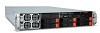
3 External and internal structure Front panel No. Icon Component 1 Default power supply unit (PSU) 2 Redundant PSU bay 3 USB 2.0 ports 4 Serial port No. Icon Component 7 Overheating/fan failure LED indicator 8 LAN port 1/2 activity indicators 9 HDD activity indicator 10 Power indicator 5 Optical disc drive 11 Reset button (ODD) 6 Power failure LED 12 Power button indicator
-
 1
1 -
2
-
3
-
4
-
5
-
6
-
7
-
8
-
9
-
 10
10 -
 11
11 -
 12
12 -
 13
13 -
 14
14 -
 15
15 -
 16
16 -
 17
17 -
 18
18 -
 19
19 -
 20
20 -
21
-
22
-
23
-
24
-
25
-
26
-
27
-
28
-
29
-
30
-
31
-
32
-
33
-
34
-
35
-
36
-
37
-
38
-
39
-
40
-
41
-
42
-
43
-
44
-
45
-
46
-
47
-
48
-
49
-
50
-
51
-
52
-
53
-
54
-
55
-
56
-
57
-
58
-
59
-
60
-
61
-
62
-
63
-
64
-
65
-
66
-
67
-
68
 |
 |

3
External and internal structure
Front panel
No.
Icon
Component
No.
Icon
Component
1
Default power
supply unit (PSU)
7
Overheating/fan
failure LED indicator
2
Redundant PSU bay
8
LAN port 1/2 activity
indicators
3
USB 2.0 ports
9
HDD activity
indicator
4
Serial port
10
Power indicator
5
Optical disc drive
(ODD)
11
Reset button
6
Power failure LED
indicator
12
Power button