Adaptec 3805 User Guide - Page 136
Adaptec RAID 3405 Aggregate Activity LED Board Connector, Adaptec RAID 3405 I2C Board Connector
 |
View all Adaptec 3805 manuals
Add to My Manuals
Save this manual to your list of manuals |
Page 136 highlights
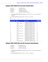
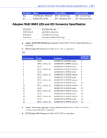
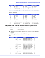
Appendix F: Controller LED and I2C Connector Quick Reference ● 136 J10: J10 Pin Number 9 10 11 12 13 14 15 16 Signal +3.3V ACT0_7_LED_L (7) +3.3V ACT0_7_LED_L (6) +3.3V ACT0_7_LED_L (5) +3.3V ACT0_7_LED_L (4) Description CONNECTOR J5-PORT0 Anode CONNECTOR J5-PORT0 Cathode CONNECTOR J5-PORT1 Anode CONNECTOR J5-PORT1 Cathode CONNECTOR J5-PORT2 Anode CONNECTOR J5-PORT2 Cathode CONNECTOR J5-PORT3 Anode CONNECTOR J5-PORT3 Cathode 22-55-2081 Pin Number 2 1 4 3 6 5 8 7 ● Adaptec RAID 3405 Aggregate Activity LED Board Connector: Molex 22-28-8022 2.54mm 1x2 RA Header or equivalent. ● LED Mating Cable Connector: Molex 50-57-9002 or equivalent. J12: Pin Number 2 1 Signal AGGREGATE4_7_L +3.3V Description Aggregate Cathode - Connector J5 Ports 0-3 Aggregate Anode ● Adaptec RAID 3405 I2C Board Connector: Molex 22-43-6030 or equivalent ● I2C Mating Cable Connector: Molex 22-43-3030 or equivalent J8: Note: The following pins are tied to Sideband Signals of SFF-8087 connector J5 (Ports 0-3) Pin Number 1 2 3 Signal I2CDATA GND I2CCLK Description I2C Data Ground I2C Clock Note: I2C signals are also routed through the SFF-8087 internal connector J5 SFF-8087 Connector J5: Pin Number B8 B9 B10 A9 A10 A11 Signal SB0_CONB SB1_CONB GND GND SB4_CONB SB5_CONB I2C Description SB0 - 2W_SCL SB1- 2W_SDA SB2 - Ground SB3 - Ground SB4 - Reset SB5 - Backplane Address SGPIO Description SB0 - SClock SB1- SLoad SB2 - Ground SB3 - Ground SB4 - SDataOut SB5 - SDataIn
-
 1
1 -
2
-
3
-
4
-
5
-
6
-
7
-
8
-
9
-
10
-
11
-
12
-
13
-
14
-
15
-
16
-
17
-
18
-
19
-
20
-
21
-
22
-
23
-
24
-
25
-
26
-
27
-
28
-
29
-
30
-
31
-
32
-
33
-
34
-
35
-
36
-
37
-
38
-
39
-
40
-
41
-
42
-
43
-
44
-
45
-
46
-
47
-
48
-
49
-
50
-
51
-
52
-
53
-
54
-
55
-
56
-
57
-
58
-
59
-
60
-
61
-
62
-
63
-
64
-
65
-
66
-
67
-
68
-
69
-
70
-
71
-
72
-
73
-
74
-
75
-
76
-
77
-
78
-
79
-
80
-
81
-
82
-
83
-
84
-
85
-
86
-
87
-
88
-
89
-
90
-
91
-
92
-
93
-
94
-
95
-
96
-
97
-
98
-
99
-
100
-
101
-
102
-
103
-
104
-
105
-
106
-
107
-
108
-
109
-
110
-
111
-
112
-
113
-
114
-
115
-
116
-
117
-
118
-
119
-
120
-
121
-
122
-
123
-
124
-
125
-
126
-
127
-
128
-
129
-
130
-
 131
131 -
 132
132 -
 133
133 -
 134
134 -
 135
135 -
 136
136 -
 137
137 -
 138
138 -
 139
139 -
 140
140 -
 141
141 -
142
-
143
-
144
-
145
-
146
-
147
-
148
-
149
-
150
-
151
-
152
-
153
-
154
-
155
-
156
-
157
-
158
 |
 |
