Airlink AICAP650W User Manual - Page 5
Airlink AICAP650W Manual
 |
View all Airlink AICAP650W manuals
Add to My Manuals
Save this manual to your list of manuals |
Page 5 highlights
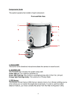
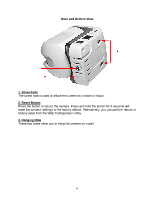
4. Camera Lens To adjust the focus of the lens, turn the lens slowly in either clockwise or counterclockwise direction until the image is in focus. DO NOT overturn the lens in either direction. 5. Flash LED The Flash LED allows you to capture video images even in dark environments. You can turn on the flash light from the Web Configuration Utility. 6. USB Port The USB port allows you to expand the storage medium by connecting a USB storage device via the USB port. Please refer to Section 7.6.2 Security Setting for information about storing image files to the USB device via motion sensor triggers and/or via scheduled settings. You can click on the Log Display sub-menu to monitor any activity for the USB port. The Camera will stop the storage and activate the buzzer when the USB storage device has less than 5% of remaining free space. 7. STATUS LED The STATUS LED indicates the configuration status with: Green light flashing: The camera is powered on and functions in normal mode. Orange-Red light flashing: Indicates the camera cannot access DHCP within the network. 8. Privacy Mode Button Press this button to enter into Privacy Mode. The camera stops monitoring in this mode. Also, you can safely remove the USB storage device from the USB port by pressing and holding this button for 5 seconds until the camera activates the buzzer. 9. LAN Port This RJ-45 connector is used to connect the 10Base-T Ethernet or 100Base-TX Fast Ethernet network cable (which should be Category 5 twisted-pair cable). The port supports the NWay protocol, allowing the camera to automatically detect or negotiate the transmission speed of the network. 10. DC Power Connector The DC power input is labeled DC 5V with a single jack socket to supply power to the camera. Power will be generated when the power supply is connected to a wall outlet. 11. Camera Stand The camera stand allows you to place the camera on a flat surface instead of hanging on the wall or installing on a tripod. 5
-
 1
1 -
 2
2 -
 3
3 -
 4
4 -
 5
5 -
 6
6 -
 7
7 -
 8
8 -
 9
9 -
 10
10 -
 11
11 -
12
-
13
-
14
-
15
-
16
-
17
-
18
-
19
-
20
-
21
-
22
-
23
-
24
-
25
-
26
-
27
-
28
-
29
-
30
-
31
-
32
-
33
-
34
-
35
-
36
-
37
-
38
-
39
-
40
-
41
-
42
-
43
-
44
-
45
-
46
-
47
-
48
-
49
-
50
-
51
-
52
-
53
-
54
-
55
-
56
-
57
-
58
-
59
-
60
-
61
-
62
-
63
-
64
-
65
-
66
-
67
-
68
-
69
-
70
-
71
-
72
-
73
-
74
-
75
-
76
-
77
-
78
-
79
-
80
-
81
-
82
-
83
-
84
-
85
 |
 |
