Akai PDP4273M1 Operating Instructions - Page 12
Rear View - no picture
 |
View all Akai PDP4273M1 manuals
Add to My Manuals
Save this manual to your list of manuals |
Page 12 highlights
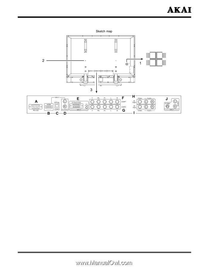
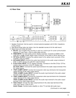
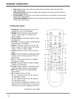
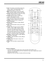
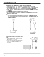
4.3 Rear View L BLACK RED BLACK RED R- + 1 Speaker Terminals: Can be used to connect external speakers with 8 Ohm impedance to the product. 2 Wall Mount fixing holes (six holes): Use the standard screws to fix the wall mount. 3 Signal input and other terminals: A. RS-232: The D-SUB 9 Pins terminal is used as a control port for serial communication between PC and Panel. (Only for after-sales service) B. HDMI INPUT: For high quality picture display purposes. Connects to HDMI or DVI (with DVI to HDMI couple) digital output connector of the DVD or HDTV Set-top box. C. OPTICAL OUTPUT: Connect the optical output to the optical input connector of the Amplifier. (Only for HDMI) D. DVI AUDIO INPUT: Connect the audio input terminal to the audio output terminal of DVD or HDTV Set-top box with DVI output terminal. E. D-Sub (VGA) INPUT: For PC display purposes. Connects to the Mini D-Sub 15 Pins analog output connector of the PC display card. PC Audio INPUT: Connect the audio input terminal to the audio output terminal of the PC output device. F. YPbPr (COMP1) INPUT: Connect the Component video input terminal to the Component output terminal of the video output device. YPbPr (COMP1) Audio INPUT: Connect the audio input terminal to the audio output terminal of the video output device. G. YPbPr (COMP2) INPUT: Connect the Component video input terminal to the Component output terminal of the video output device. YPbPr (COMP2) Audio INPUT: Connect the audio input terminal to the audio output terminal of the video output device. H. Video Output: Connect the video output terminal to the video input terminal of the video input device. (Only for AV) Audio Output: Connect audio amplifier or other TV set that with audio input. (Continued on next page) 11
-
 1
1 -
2
-
3
-
4
-
5
-
6
-
 7
7 -
 8
8 -
 9
9 -
 10
10 -
 11
11 -
 12
12 -
 13
13 -
 14
14 -
 15
15 -
 16
16 -
 17
17 -
18
-
19
-
20
-
21
-
22
-
23
-
24
-
25
-
26
-
27
-
28
-
29
-
30
-
31
-
32
-
33
-
34
-
35
-
36
 |
 |