Alpine C701 Owners Manual - Page 8
Basic Connections Diagram - h701
 |
UPC - 793276420183
View all Alpine C701 manuals
Add to My Manuals
Save this manual to your list of manuals |
Page 8 highlights
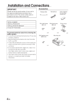
Installation and Connections 3 Mount the spacer and bracket to the control unit. Next, securely mount the factory brackets removed from the factory radio, to the control unit assembly. 4 Mount the spacer on the control unit using the included screws. Spacer Flat head screws (M5 x 8) Control unit Bracket Flush Mounting the control unit 1 Make a cut-out approximately 178 (width) by 50 (height) mm (7 inches by 2 inches) in size at your desired mounting location. WARNING When making cut-outs, be careful not to damage pipes, tanks, electric wires, etc. Doing so could lead to accidents or fire. 2 After step 2 on "Mounting other units" of "Mounting the control unit" page 5, remove the side bracket. Side bracket Pan head screw (M3 x 5) x 2 5 Attach the flush mount brackets to the control unit using the included screws. Mount this assembly into the prepared cut-out. Flush mount Self-tapping screw (M2.6 x 8) x 4 Face plate Basic Connections Diagram CAUTION Do not connect or disconnect the display cable when the power of the unit is on. Display Side bracket 3 Remove the spacer from the bracket. Spacer Bracket Display cable 6-EN PXA-H701 CENTER SELECTABLE (L) SUBWOOFER MIC (R) FRONT 1 FRONT 2 (FULL RANGE /TWEETER) REAR SUBWOOFER CONTROL UNIT OUTPUT CD/DVD H.U. CHG DVD DIGITAL 1 DIGITAL 2 DIGITAL 3 INPUT GUIDE (L) (R) ANALOG 1 Ai-NET IN CHANGER IN POWER SUPPLY ANALOG 2 ANALOG 3
-
 1
1 -
2
-
 3
3 -
 4
4 -
 5
5 -
 6
6 -
 7
7 -
 8
8 -
 9
9 -
 10
10 -
 11
11 -
 12
12
 |
 |
