Alpine CDE-110 Owner's Manual (english) - Page 2
Installation and Connections - review
 |
View all Alpine CDE-110 manuals
Add to My Manuals
Save this manual to your list of manuals |
Page 2 highlights
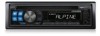
USB memory (Optional) SOURCE/ BAND/ / USB Memory Connection (Optional) Connect USB memory 1 Open the cover of the USB connection terminal. 2 Connect the USB memory directly to the USB connection terminal, or via the USB cable. This unit USB Connection Terminal USB memory (Sold Separately) Controlling USB memory (Optional) A USB memory device may be connected to this unit. With USB memory connected, playback of files on the device is controlled from this unit. • The controls on this unit for USB memory operation are operative only when a USB memory is connected. Note * CDE-110UB does not support WMA. Playing MP3/WMA Files with the USB memory (Optional) If you connect a USB memory containing MP3/WMA, you can play these files on this unit. 1 Press SOURCE/ to switch to the USB AUDIO mode. The mode will change every time the button is pressed. RADIO CD* 1 USB * 2 AUX RADIO * 1 Displayed only when a disc has been inserted. * 2 Displayed only when USB memory is connected. 2 To pause playback, press BAND/ / . Pressing BAND/ / again will resume the playback. • The root folder is displayed as "ROOT" in the Folder Name Search mode. • This unit plays back files on a USB memory device with the same controls and modes as playback of CDs containing MP3/WMA. For details, refer to "CD/MP3/WMA". • Before disconnecting USB memory, be sure to change to another source or set to pause. • The playback time may not be correctly displayed when a VBR (Variable Bit Rate) recorded file is played back. or USB memory Cable (Sold (Sold Separately) Separately) Remove USB memory 1 Carefully, pull out the USB memory from the USB cable or the USB connection terminal. 2 Close the cover of the USB connection terminal. • Change to a source other than the USB memory mode, then remove the USB memory. If the USB memory is removed in the USB memory mode, data may be damaged. • When removing USB memory, pull it out straight. • If sound is not output or USB memory is not recognised even when USB memory is connected, remove USB memory once, then connect it again. • Route the USB cable away from other cables, etc. • After removing the USB memory, close the cover of the USB connection terminal to prevent dust or foreign objects from entering and causing a malfunction. About MP3/WMA File of USB Memory Playing back MP3/WMA MP3/WMA files are prepared, then stored to a USB memory. This unit can recognise at least 999 folders (including root folder) and 255 files per folder stored in USB memory. Playback may not be performed if a USB memory exceeds the limitations described above. Do not make a file's playback time more than 1,000 minutes. Media supported This device can play back USB memory media. Corresponding File Systems This device supports FAT 12/16/32 for USB memory device. Information In Case of Difficulty If you encounter a problem, please turn the power off, then on again. If the unit is still not functioning normally, please review the items in the following checklist. This guide will help you isolate the problem if the unit is at fault. Otherwise, make sure the rest of your system is properly connected or consult your authorized Alpine dealer. Basic No function or display. • Vehicle's ignition is off. - If connected following instructions, the unit will not operate with the vehicle's ignition off. • Improper power lead (Red) and battery lead (Yellow) connections. - Check power lead and battery lead connections. • Blown fuse. - Check the fuse of the unit; replace with the proper value if necessary. Radio Unable to receive stations. • No antenna or open connection in cable. - Make sure the antenna is properly connected; replace the antenna or cable if necessary. Unable to tune stations in the seek mode. • If the area you are in is a primary signal area, the antenna may not be grounded and connected properly. - Check your antenna connections; make sure the antenna is properly grounded at its mounting location. • The antenna may not be the proper length. - Make sure the antenna is fully extended; if broken, replace the antenna with a new one. Broadcast is noisy. • The antenna is not the proper length. - Extend the antenna fully; replace it if it is broken. • The antenna is poorly grounded. - Make sure the antenna is grounded properly at its mounting location. CD CD Player not functioning. • Out of operating temperature range +70°C (+158°F) for CD. - Allow the vehicle's interior (or trunk) temperature to cool. CD playback sound is wavering. • Moisture condensation in the CD Module. - Allow enough time for the condensation to evaporate (about 1 hour). CD insertion not possible. • A CD is already in the CD player. - Eject the CD and remove it. • The CD is being improperly inserted. - Make sure the CD is being inserted following instructions in the CD Player Operation section. Unable to fast forward or backward the CD. • The CD has been damaged. - Eject the CD and discard it; using a damaged CD in your unit can cause damage to the mechanism. CD playback sound skips due to vibration. • Improper mounting of the unit. - Securely re-mount the unit. • The disc is very dirty. - Clean the disc. • The disc has scratches. - Change the disc. • The pick-up lens is dirty. - Do not use a commercially available lens cleaner disc. Consult your nearest Alpine dealer. CD playback sound skips without vibration. • The disc is dirty or scratched. - Clean the disc; damaged disc should be replaced. Error displays (built-in CD player only). • Mechanical error. - Press . After the error indication disappears, insert the disc again. If the above-mentioned solution does not solve the problem, consult your nearest Alpine dealer. CD-R/CD-RW playback not possible. • Close session (finalization) has not been performed. - Perform finalization and attempt playback again. MP3/WMA MP3, WMA is not played back. • Writing error occurred. The MP3/WMA format is not compatible. - Make sure the MP3/WMA has been written in a supported format. Refer to "About MP3/WMA", then rewrite in the format supported by this device. Indication for CD Player • The disc is dirty or upside down. - Press the button and eject the CD. If not ejecting, consult your Alpine dealer. • The disc has scratches. - Press the button and eject the CD. If not ejecting, consult your Alpine dealer. • Mechanism error. - Consult your Alpine dealer. • A sampling rate/bit rate not supported by the unit is used. - Use a sampling rate/bit rate that is supported by the unit. • A copy-protected WMA file was played back. - You can only play back non-copy-protected files. Indication for USB memory • No song (file) is stored in the USB memory. - Connect the USB memory device after storing songs (files). • A USB device that is not supported by the unit is connected. - Connect a USB device that is supported by the unit. • Abnormal current is run to the USB connector device (an error message may be displayed if the USB device that is not compatible with the unit is connected). USB memory is a malfunction or it is shorted. - Disconnect the USB memory device and turn off the power and turn on Connect another USB memory. • Communication error. - Turn the ignition key off, and then set to ON again. • A sampling rate/bit rate not supported by the unit is used. - Use a sampling rate/bit rate that is supported by the unit. • A copy-protected WMA file was played back. - You can only play back non-copy-protected files. Specifications FM RADIO SECTION Tuning Range Usable Sensitivity Frequency Response Alternate Channel Selectivity Stereo Separation Image Rejection Ratio IF Rejection Ratio Signal-to-Noise Ratio 87.5-108.0 MHz / 87.7-107.9 MHz (CDE-110C/110E/110UB) / (CDE-110) 5 dB/µV (S/N 30 dB) 30-15,000 Hz (±3 dB) 75 dB 30 dB 70 dB 100 dB 62 dB AM RADIO SECTION Tuning Range Usable Sensitivity 531-1,602 kHz / 530-1,710 kHz (CDE-110C/110E/110UB) / (CDE-110) 28 dB/µV (S/N 20 dB) CD PLAYER SECTION Sampling Range DA Converter Pick-up Type Light Source Wave length Laser Power Frequency Response Signal-to-Noise Ratio Total Harmonic Distortion Wow & Flutter Channel Separation 8 times oversampling 1 bit DAC System 3-beam Photo Detector Pick Up Semiconductor laser 790 nm CLASS I 20-20,000 Hz (±1 dB) 96 dB 0.01% (at 1 kHz) Below measurable limits 85 dB USB SECTION USB requirements Maximum Supply Compatibility 1.1/2.0 Full Speed 500 mA Front AUX input Input Impedance Allowable external input Co n n ecto r 10 kohms 2.0 V 3.5 mm ϕ Stereo mini-pin GENERAL Power Requirement Current Consumption Maximum Power Output Power Output Speaker Impedance Pre-Output Voltage* Pre-Output Impedance* Dimensions (W × H × D) W eight 12 V DC (11-16 V allowable), Test volage 14.4 V, Negative ground Less than 2.1 A (CD mode; 0.5 W x 4) 50 W × 4 (at 1 kHz) volume control maximum 18 W x 4 (1kHz, 1 %, 4 ohms) 4-8 ohms 2 V (CD mode, 1 kHz, 0dB) 200 ohms 178 × 50 × 160 mm 1.2 kg • Due to continuous product improvement, specifications and design are subject to change without notice. 11 Connections Blue ANT CONT Blue/White AMP CONT Red IGNITION Yellow BATTERY Black GND Gray SPEAKER RIGHT FRONT Gray/Black Violet/Black SPEAKER RIGHT REAR Violet Green SPEAKER LEFT REAR Green/Black White/Black SPEAKER LEFT FRONT White Antenna To power antenna To amplifier Ignition Key Battery Speakers Front Right Rear Right Rear Left Front Left Amplifier Speakers Rear Left Rear Right 12 Antenna Receptacle ANT CONT Lead (Blue) Connect this lead to the +B terminal of your power antenna, if applicable. • This lead should be used only for controlling the vehicle's power antenna. Do not use this lead to turn on an amplifier etc. AMP CONT Lead (Blue/White) Connect this lead to the remote turn-on lead of your amplifier or signal processor. Switched Power Lead (Ignition) (Red) Connect this lead to an open terminal on the vehicle's fuse box or another unused power source which provides (+)12V only when the ignition is turned on or in the accessory position. Battery Lead (Yellow) Connect this lead to the positive (+) post of the vehicle's battery. Ground Lead (Black) Connect this lead to a good chassis ground on the vehicle. Make sure the connection is made to bare metal and is securely fastened using the sheet metal screw provided. Power Supply Connector Right Front (+) Speaker Output Lead (Gray) Right Front (-) Speaker Output Lead (Gray/Black) Right Rear (-) Speaker Output Lead (Violet/Black) Right Rear (+) Speaker Output Lead (Violet) Left Rear (+) Speaker Output Lead (Green) Left Rear (-) Speaker Output Lead (Green/Black) Left Front (-) Speaker Output Lead (White/Black) Left Front (+) Speaker Output Lead (White) Fuse Holder (15A) Rear Output RCA Connectors RED is right and WHITE is left. RCA Extension Cable (sold separately) Front AUX Input Terminal This terminal allows for input of audio from an external device (such as a portable player), using a commerciallyavailable converter cable. USB Connection Terminal Connect USB memory (sold separately) 13 14 Installation and Connections Before installing or connecting the unit, please read the following and "Operating Instructions" of this manual thoroughly for proper use. Warning MAKE THE CORRECT CONNECTIONS. Failure to make the proper connections may result in fire or product damage. USE ONLY IN CARS WITH A 12 VOLT NEGATIVE GROUND. (Check with your dealer if you are not sure.) Failure to do so may result in fire, etc. BEFORE WIRING, DISCONNECT THE CABLE FROM THE NEGATIVE BATTERY TERMINAL. Failure to do so may result in electric shock or injury due to electrical shorts. DO NOT ALLOW CABLES TO BECOME ENTANGLED IN SURROUNDING OBJECTS. Arrange wiring and cables in compliance with the manual to prevent obstructions when driving. Cables or wiring that obstruct or hang up on places such as the steering wheel, shift lever, brake pedals, etc. can be extremely hazardous. DO NOT SPLICE INTO ELECTRICAL CABLES. Never cut away cable insulation to supply power to other equipment. Doing so will exceed the current carrying capacity of the wire and result in fire or electric shock. DO NOT DAMAGE PIPE OR WIRING WHEN DRILLING HOLES. When drilling holes in the chassis for installation, take precautions so as not to contact, damage or obstruct pipes, fuel lines, tanks or electrical wiring. Failure to take such precautions may result in fire. DO NOT USE BOLTS OR NUTS IN THE BRAKE OR STEERING SYSTEMS TO MAKE GROUND CONNECTIONS. Bolts or nuts used for the brake or steering systems (or any other safety-related system), or tanks should NEVER be used for installations or ground connections. Using such parts could disable control of the vehicle and cause fire etc. KEEP SMALL OBJECTS SUCH AS BATTERIES OUT OF THE REACH OF CHILDREN. Swallowing them may result in serious injury. If swallowed, consult a physician immediately. DO NOT INSTALL IN LOCATIONS WHICH MIGHT HINDER VEHICLE OPERATION, SUCH AS THE STEERING WHEEL OR SHIFT LEVER. Doing so may obstruct forward vision or hamper movement etc. and results in serious accident. Caution HAVE THE WIRING AND INSTALLATION DONE BY EXPERTS. The wiring and installation of this unit requires special technical skill and experience. To ensure safety, always contact the dealer where you purchased this product to have the work done. USE SPECIFIED ACCESSORY PARTS AND INSTALL THEM SECURELY. Be sure to use only the specified accessory parts. Use of other than designated parts may damage this unit internally or may not securely install the unit in place. This may cause parts to become loose resulting in hazards or product failure. ARRANGE THE WIRING SO IT IS NOT CRIMPED OR PINCHED BY A SHARP METAL EDGE. Route the cables and wiring away from moving parts (like the seat rails) or sharp or pointed edges. This will prevent crimping and damage to the wiring. If wiring passes through a hole in metal, use a rubber grommet to prevent the wire's insulation from being cut by the metal edge of the hole. DO NOT INSTALL IN LOCATIONS WITH HIGH MOISTURE OR DUST. Avoid installing the unit in locations with high incidence of moisture or dust. Moisture or dust that penetrates into this unit may result in product failure. Precautions • Be sure to disconnect the cable from the (-) battery post before installing your CDE-110/110C/110E/110UB. This will reduce any chance of damage to the unit in case of a short-circuit. • Be sure to connect the colour coded leads according to the diagram. Incorrect connections may cause the unit to malfunction or damage to the vehicle's electrical system. • When making connections to the vehicle's electrical system, be aware of the factory installed components (e.g. on-board computer). Do not tap into these leads to provide power for this unit. When connecting the CDE-110/110C/110E/110UB to the fuse box, make sure the fuse for the intended circuit of the CDE-110/ 110C/110E/110UB has the appropriate amperage. Failure to do so may result in damage to the unit and/or the vehicle. When in doubt, consult your Alpine dealer. • The CDE-110/110C/110E/110UB uses female RCA-type jacks for connection to other units (e.g. amplifier) having RCA connectors. You may need an adaptor to connect other units. If so, please contact your authorized Alpine dealer for assistance. • Be sure to connect the speaker (-) leads to the speaker (-) terminal. Never connect left and right channel speaker cables to each other or to the vehicle body. IMPORTANT Please record the serial number of your unit in the space provided below and keep it as a permanent record. The serial number or the engraved serial number is located on the upper of the unit. SERIAL NUMBER: INSTALLATION DATE: INSTALLATION TECHNICIAN: PLACE OF PURCHASE: 15 Installation Caution Do not block the unit's heat sink, thus preventing air circulation. If blocked, heat will accumulate inside the unit and may cause a fire. Heat sink Detachable Front Panel Caution When you install this unit in your car, do not remove the detachable front panel. If the detachable front panel is removed during installation, you might press too hard and warp the metal plate that holds it in place. • The main unit must be mounted within 30 degrees of the horizontal plane, back to front. Less than 30° 1 Bracket Mounting Sleeve (Included) Rubber Cap (Included) Dashboard Bolt Stud (Included) Snapping Point This unit Remove the mounting sleeve from the main unit (see "Removal"). 2 Hex Nut (M5) Screw Metal Mounting Strap *2 Bolt Stud (Included) *1 This unit Ground Lead Chassis Reinforce the head unit with the metal mounting strap (not supplied). Secure the ground lead of the unit to a clean metal spot using a screw (* 1) already attached to the vehicle's chassis. • For the screw marked "*2", use an appropriate screw for the chosen mounting location. Connect each input lead coming from an amplifier to the corresponding output lead coming from the left rear of the CDE-110/110C/110E/110UB. Connect all other leads of the CDE-110/110C/110E/110UB according to details described in the CONNECTlONS section. 3 Slide the CDE-110/110C/110E/110UB into the dashboard until it clicks. This ensures that the unit is properly locked and will not accidentally come out from the dashboard. Install the detachable front panel. Removal 1. Remove the detachable front panel. 2. Insert the bracket keys into the unit, along the guides on either side. The unit can now be removed from the mounting sleeve. This unit Bracket Keys (Included) 3. Pull the unit out, keeping it unlocked as you do so. This unit Ground Lead *3 Front Frame (Included) Screws (M5 × 8) Mounting Bracket Secure the ground lead of the unit to a clean metal spot using a screw (*3) already attached to the vehicle's chassis. 16 17 To prevent external noise from entering the audio system. • Locate the unit and route the leads at least 10 cm away from the car harness. • Keep the battery power leads as far away from other leads as possible. • Connect the ground lead securely to a bare metal spot (remove any paint, dirt or grease if necessary) of the car chassis. • If you add an optional noise suppressor, connect it as far away from the unit as possible. Your Alpine dealer carries various noise suppressors, contact them for further information. • Your Alpine dealer knows best about noise prevention measures so consult your dealer for further information. 18
-
 1
1 -
 2
2
 |
 |