Alpine MRX-M50 User Manual
Alpine MRX-M50 Manual
 |
UPC - 793276301062
View all Alpine MRX-M50 manuals
Add to My Manuals
Save this manual to your list of manuals |
Alpine MRX-M50 manual content summary:
- Alpine MRX-M50 | User Manual - Page 1
el equipo, luego guarde el manual para usarlo como referencia en el futuro. English CONTENTS WARNING 2 CAUTION 3 INSTALLATION 4 ATTACHING THE TERMINAL COVERS 5 CONNECTIONS 6 CONNECTION CHECK LIST 11 SWITCH SETTINGS 12 SYSTEM DIAGRAMS 13 SPECIFICATIONS 16 SERVICE CARE 17 ACCESSORIES • Self - Alpine MRX-M50 | User Manual - Page 2
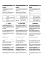
enjoyment. In case of problems when installing your MRX-M100/MRX-M50, please contact your authorized ALPINE dealer. CAUTION: These controls are for tuning your system. Please consult your authorized Dealer for adjustment. WARNING CAUTION This symbol means important instructions. Failure to heed - Alpine MRX-M50 | User Manual - Page 3
HALT USE IMMEDIATELY IF A PROBLEM APPEARS. Failure to do so may cause personal injury or damage to the product. Return it to your authorized Alpine dealer or the nearest Alpine Service Center for repairing. HAVE THE WIRING AND INSTALLATION DONE BY EXPERTS. The wiring and installation of this unit - Alpine MRX-M50 | User Manual - Page 4
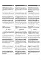
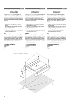
English Français Español INSTALLATION Due to the high power output of the MRX-M100/MRX-M50, considerable heat is produced when the amplifier is in operation. For this reason, the amplifier should be mounted in a location which will allow for free circulation of air, such as inside the trunk. For - Alpine MRX-M50 | User Manual - Page 5
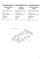
con los tornillos (M3 x 10) suministrados, tal como se indica en la siguiente figura. A Tapa derecha del terminal B Tapa izquierda del terminal C Tornillo (M3 x 10) NOTA: No eleve ni transporte la unidad cogiéndola de las tapas del terminal. C A C B Fig - Alpine MRX-M50 | User Manual - Page 6
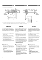
Locate the unit and route the leads at least 10 cm (3-15/16") away from the car harness. • Keep the battery power leads as far away from other leads as possible Alpine conoce la mejor forma de evitar el ruido. Solicítele más información. a Speaker Output Terminals The MRX-M100/MRX-M50 has one set - Alpine MRX-M50 | User Manual - Page 7
these wires to the speaker output leads of your head unit. The MRX-M100/MRX-M50 accepts input from high power or standard power head units. NOTES: • Use either RCA line level or speaker level inputs. Do not connect both at the same time. • For the"Speaker Level Input System"setting, connecting - Alpine MRX-M50 | User Manual - Page 8
wires to the speaker output leads of your head unit. The MRX-M100/MRX-M50 accepts input from high power or standard power This is an ideal output for driving a second subwoofer amp. This output is full-range, and is not replace appropriate gain level setting between the amplifier and head unit. h - Alpine MRX-M50 | User Manual - Page 9
one amplifier, a distribution block should be used. See below for wire gauge recommendations for distribution block connection to battery and ground (depends upon wire length necessary): MRX-M100 2AWG(33mm2) or 1/0AWG(53mm2) MRX-M50 4AWG(21mm2) or 2AWG(33mm2) Ensure that you install a correctly - Alpine MRX-M50 | User Manual - Page 10
set screw with the hexagon wrench (included) to secure the lead. (Fig. 6) Before making this connection, use insulated shrink tubing to cover any exposed wire une panne de fonctionnement ou l'interruption du son. • D'autre part, si la longueur du conducteur est trop longue, un court-circuit 10 - Alpine MRX-M50 | User Manual - Page 11
installed in-line on the MRX-M100/MRX-M50 turn-on lead. This switch will then be used to turn on (and off) the MRX-M100/ MRX-M50. Therefore, the switch should be mounted so that is accessible by the driver. Make sure the switch is turned off when the vehicle is not running. Otherwise, the amplifier - Alpine MRX-M50 | User Manual - Page 12
Français Español tuvw Fig. 8 x SWITCH SETTINGS NOTE: Before switching each Selector Switch, turn off the power and insert a small screwdriver, etc., perpendicularly to the Switch. t Input Gain Adjustment Control Set the MRX-M100/MRX-M50 input gain - Alpine MRX-M50 | User Manual - Page 13
DEL SISTEMA • TYPICAL SYSTEM CONNECTIONS/CONNEXIONS TYPIQUES DU SYSTÈME/CONEXIONES TÍPICAS DEL SISTEMA 2 d f 25 25 25 25 (Left side/Côté gauche/Lado izquierdo) [English] y Y-Adapter (Sold Separately) z RCA Extension Cable (Sold Separately) 1 Head Unit - Alpine MRX-M50 | User Manual - Page 14
. MRX-M100> 2 d f (L) 25 25 25 25 (Left side/Côté gauche/Lado izquierdo) e (R) (Right side/Côté droit/ Lado derecho) z (L) (R) z 1 2 d f (L) 25 25 25 25 (Left side/Côté gauche/Lado izquierdo) e (R) (Right side/Côté droit/ Lado derecho) Fig. 10 Important Tips on Bridging an Amplifier - Alpine MRX-M50 | User Manual - Page 15
f 25 25 25 25 (Left side/Côté gauche/Lado izquierdo) 1 e (Right side/Côté droit/ Lado derecho) 2 h RR RR 1 Fig. 12 ★1 For the "Speaker Level Input System" setting, connecting the Remote Turn Remote Turn-On Lead to an incoming power supply cord (accessory power) in the ACC position. ★2 Use - Alpine MRX-M50 | User Manual - Page 16
RUX-KNOB Dimensions Width (Heat Sink) Weight Height Depth MRX-M100 600W RMS x 1 1000W RMS x 1 500W RMS x 1 - Alpine MRX-M50 | User Manual - Page 17
ñol SERVICE CARE ♦ IMPORTANT NOTICE This Amplifier has been type tested and found to comply with the limits for a Class B computing device in accordance with the specifications in Subpart J of Part 15 of FCC Rules. This equipment generates and uses radio frequency energy, and it must be installed - Alpine MRX-M50 | User Manual - Page 18
- Alpine MRX-M50 | User Manual - Page 19
- Alpine MRX-M50 | User Manual - Page 20
-
 1
1 -
 2
2 -
 3
3 -
 4
4 -
 5
5 -
 6
6 -
 7
7 -
8
-
9
-
10
-
11
-
12
-
13
-
14
-
15
-
16
-
17
-
18
-
19
-
20
 |
 |

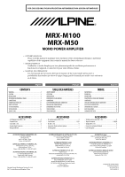
OWNER’S MANUAL
Please read this manual to maximize your enjoyment of the outstanding performance and feature
capabilities of the equipment, then retain the manual for future reference.
MODE D’EMPLOI
Veuillez lire ce mode d’emploi pour tirer pleinement profit des excellentes performances et
fonctions de cet appareil, et conservez-le pour toute référence future.
MANUAL DE OPERACIÓN
Lea este manual, por favor, para disfrutar al máximo de las excepcionales prestaciones y
posibilidades funcionales que ofrece el equipo, luego guarde el manual para usarlo como referencia
en el futuro.
•
•
•
FOR CAR USE ONLY/POUR APPLICATION AUTOMOBILE/PARA USO EN AUTOMÓVILES
MRX-M100
MRX-M50
MONO POWER AMPLIFIER
English
Français
Español
CONTENTS
WARNING
.................................................................................
2
CAUTION
...................................................................................
3
INSTALLATION
..........................................................................
4
ATTACHING THE TERMINAL COVERS
...........................................
5
CONNECTIONS
..........................................................................
6
CONNECTION CHECK LIST
........................................................
11
SWITCH SETTINGS
...................................................................
12
SYSTEM DIAGRAMS
................................................................
13
SPECIFICATIONS
......................................................................
16
SERVICE CARE
.........................................................................
17
TABLE DES MATIÈRES
AVERTISSEMENT
.......................................................................
2
ATTENTION
...............................................................................
3
INSTALLATION
..........................................................................
4
FIXATION DES CACHE-BORNES
..................................................
5
CONNEXIONS
............................................................................
6
LISTE DE VÉRIFICATION DES CONNEXIONS
...............................
11
RÉGLAGES DE COMMUTATEUR
................................................
12
DIAGRAMMES DU SYSTÈME
....................................................
13
SPÉCIFICATIONS
......................................................................
16
SOINS PRATIQUES
...................................................................
17
ÍNDICE
ADVERTENCIA
...........................................................................
2
PRUDENCIA
..............................................................................
3
INSTALACIÓN
............................................................................
4
FIJACIÓN DE LAS TAPAS DEL TERMINAL
.....................................
5
CONEXIONES
.............................................................................
6
LISTA DE COMPROBACIÓN DE CONEXIONES
.............................
11
AJUSTES DEL INTERRUPTOR
....................................................
12
DIAGRAMAS DEL SISTEMA
......................................................
13
ESPECIFICACIONES
..................................................................
16
CUIDADOS PRÁCTICOS
............................................................
17
ACCESSORIES
Self-Tapping Screw (M4 × 20)
..............................................
4
Terminal Cover
................................................................
1 SET
Screw (M3 × 10)
..................................................................
4
Speaker Input Connector
......................................................
1
Hexagon Wrench
..................................................................
1
•
•
•
•
•
ACCESSOIRES
Vis autotaraudeuse (M4 × 20)
..............................................
4
Cache-bornes
.................................................................
1 JEU
Vis (M3 × 10)
.......................................................................
4
Connecteur d’entrée de haut-parleur
....................................
1
Clé hexagonale
.....................................................................
1
•
•
•
•
•
ACCESORIOS
Tornillo autorroscante (M4 × 20)
.........................................
4
Tapa del terminal
.......................................................
1 JUEGO
Tornillo (M3 × 10)
................................................................
4
Conector de entrada del altavoz
...........................................
1
Llave hexagonal
...................................................................
1
•
•
•
•
•
ALPINE ELECTRONICS MARKETING, INC.
1-1-8 Nishi Gotanda,
Shinagawa-ku,
Tokyo 141-0031, Japan
Phone
03-5496-8231
ALPINE ELECTRONICS OF AMERICA, INC.
19145 Gramercy Place, Torrance,
California 90501, U.S.A.
Phone 1-800-ALPINE-1 (1-800-257-4631)
ALPINE ELECTRONICS OF CANADA, INC.
777 Supertest Road, Toronto,
Ontario M3J 2M9, Canada
Phone 1-800-ALPINE-1 (1-800-257-4631)
ALPINE ELECTRONICS OF AUSTRALIA PTY. LTD.
161-165 Princes Highway, Hallam
Victoria 3803, Australia
Phone 03-8787-1200
ALPINE ELECTRONICS GmbH
Wilhelm-Wagenfeld-Str. 1-3,
80807 München, Germany
Phone 089-32 42 640
ALPINE ELECTRONICS OF U.K. LTD.
Alpine House
Fletchamstead Highway, Coventry CV4 9TW,
U.K.
Phone 0870-33 33 763
ALPINE ELECTRONICS FRANCE S.A.R.L.
(RCS PONTOISE B 338 101 280)
98, Rue de la Belle Etoile, Z.I. Paris Nord Il,
B.P. 50016, 95945 Roissy Charles de Gaulle
Cedex, France
Phone 01-48638989
ALPINE ITALIA S.p.A.
Viale C. Colombo 8, 20090 Trezzano
Sul Naviglio (MI), Italy
Phone 02-484781
ALPINE ELECTRONICS DE ESPAÑA, S.A.
Portal de Gamarra 36, Pabellón, 32
01013 Vitoria (Alava)-APDO 133, Spain
Phone 945-283588
ALPINE ELECTRONICS (BENELUX) GmbH
Leuvensesteenweg 510-B6,
1930 Zaventem, Belgium
Phone 02-725-13 15
Qingdao Dongli Xinhaiyuan Printing Co., Ltd.
No.17, jiushuidong road,Qingdao, China
Designed by ALPINE Japan
Printed in China (Y)
68-13530Z78-A
M3514429010