American Standard 3073.216.020 Installation Instructions - Page 3
Repair Parts List
 |
UPC - 033056710333
View all American Standard 3073.216.020 manuals
Add to My Manuals
Save this manual to your list of manuals |
Page 3 highlights
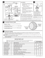
10 TOP PUSH BUTTON ARM NIPPLE CRITICAL LEVEL MARK ("C.L.") MUST BE 1" ABOVE OVERFLOW PIPE FLOAT CUP FILL VALVE SET WATER LEVEL HERE VALVE BODY ADJUSTABLE HEIGHT LOCK NUT CONE WASHER COUPLING NUT (HAND TIGHT ONLY) WATER LEVEL ADJUSTMENT ROD SHANK WASHER THREADED SHANK PARTS FOR WATER CONNECTION (SEE STEP 9) ADJUSTMENTS 11 a. Adjust water level. Water level should be adjusted to level indicated on tank by adjusting float cup. See Step 11 for water level adjustment method. FLUSH VALVE b. Make sure Full Flush Adjustment is at the bottom setting (0). A higher setting will result in less water and is not PARTIAL FLUSH ADJUSTMENT c. recommended. Make sure Partial Flush Adjustment is at the bottom setting (0). A higher setting FULL FLUSH ADJUSTMENT will result in less water and is not recommended. BAYONET RELEASE NOTE: The Fill Valve does not have a refill SILICONE SEAL tube. The refill port on the Fluidmaster fill VALVE SEAT valve is 100% blocked off. Please ensure that the correct repair part is used as this fill valve varies from the standard Fluidmaster 400A. Turn on water supply. Submerge the FLOAT CUP under the water for 30 seconds. Adjust the water to desired level by turning WATER LEVEL ADJUSTMENT ROD and moving FLOAT CUP up or down. • To remove Flush Valve, apply slight downward pressure and twist it until the flush valve disengages from the bayonet. Diagram 1 • To reinstall Flush Valve, reverse the above procedure making sure the blue (Partial Flush Button) will line up with the Partial Flush Button on the Tank Lid. 12 FLUSH BUTTONS ON TANK • Pressing both buttons at once will flush the half flush amount .8 gal/flush or 3L/flush. • The Partial Flush Button should line up over the blue actuator on the flush tower in the tank. • The Full Flush Button should line up over the white actuator on the flush tower in the tank. Small button for liquid waste. .8 gal/flush 3L/flush Large button for solid waste. 1.6 gal/flush 6L/flush 13 ! CARE AND CLEANING When cleaning your toilet, wash it with mild, soapy water, rinse thoroughly with clear water and dry with a soft cloth. Avoid detergents, disinfectants, or cleaning products in aerosol cans. NEVER use abrasive scouring powders or abrasive pads on your toilet seat. Some bathroom chemicals and cosmetics may damage the seat's finish. WARNING: Do not use in-tank cleaners. Products containing chlorine (calcium hypochlorite) can seriously damage fittings in the tank. This damage can cause leakage and property damage. American Standard shall not be responsible or liable for any tank fitting damage caused by the use of cleaners containing chlorine (calcium hypochlorite). REPAIR PARTS LIST Repair parts are determined by toilet tank number which can be found marked inside tank. NOTE: "XXX" represents color or trim finish options. Specify when ordering. PART NO. 735130-400-XXX0A 738565-426.0070A 738565-427.0070A 7301143-0070A 7381002-400.0070A 7381002-401.0070A 7381003-XXX0A 034783-XXX0A 760127-XXX0A 760130-XXX0A 7381042-0070A 760134-0200A DESCRIPTION TANK COVER WITH PUSH BUTTON FLUIDMASTER 400A VALVE FLUIDMASTER 400A VALVE TANK COUPLING KIT #258 DUAL FLUSH VALVE DUAL FLUSH VALVE PUSH BUTTON ASSEMBLY - TOP MOUNT BOLT CAP KIT TOILET SEAT (ELONGATED RIM ONLY ) TOILET SEAT - SLOW CLOSE (ELONGATED RIM ONLY) FLUSH VALVE SILICONE SEAL HINGE KIT FOR SLOW CLOSE SEAT - 3 - TANK NUMBER 4035.216 4035.516 ✔ ✔ ✔ ✔ ✔ ✔ ✔ ✔ ✔ ✔ ✔ ✔ ✔ ✔ ✔ ✔ ✔ ✔ ✔ ✔ 7301144-100 Rev. H
-
 1
1 -
 2
2 -
 3
3 -
 4
4
 |
 |
