Asus A7N8X-E Deluxe A7N8X-E Deluxe User's Manual
Asus A7N8X-E Deluxe Manual
 |
View all Asus A7N8X-E Deluxe manuals
Add to My Manuals
Save this manual to your list of manuals |
Asus A7N8X-E Deluxe manual content summary:
- Asus A7N8X-E Deluxe | A7N8X-E Deluxe User's Manual - Page 1
Motherboard A7N8X-E Deluxe User Guide - Asus A7N8X-E Deluxe | A7N8X-E Deluxe User's Manual - Page 2
Product warranty or service will not be extended if: (1) the product is repaired, modified or altered, unless such repair, modification of alteration is authorized in writing by ASUS; or (2) the serial number of the product is defaced or missing. ASUS PROVIDES THIS MANUAL "AS IS" WITHOUT WARRANTY - Asus A7N8X-E Deluxe | A7N8X-E Deluxe User's Manual - Page 3
ix A7N8X-E Deluxe specifications summary x Chapter 1: Product introduction 1.1 Welcome 1-1 1.2 Package contents 1-1 1.3 Special features 1-2 1.3.1 Product Highlights 1-2 1.3.2 Unique ASUS features 1-3 Chapter 2: Hardware information 2.1 Before you proceed 2-1 2.2 Motherboard overview - Asus A7N8X-E Deluxe | A7N8X-E Deluxe User's Manual - Page 4
AwardBIOS Flash Utility 4-2 4.1.3 ASUS Update 4-5 4.2 BIOS Setup program 4-7 4.2.1 BIOS menu screen 4-8 4.2.2 Menu bar 4-8 4.2.3 Navigation keys 4-8 4.2.4 Menu items 4-9 4.2.5 Sub-menu items 4-9 4.2.6 Configuration fields 4-9 4.2.7 General help 4-9 4.2.8 Pop-up window 4-9 4.2.9 Scroll bar - Asus A7N8X-E Deluxe | A7N8X-E Deluxe User's Manual - Page 5
Applications 5-9 5.3.7 Information 5-10 5.4 NVIDIA® NVSwap 1.0 Utility 5-11 5.5 RAID 0/RAID 1 Configurations 5-13 5.5.1 Install the hard disks 5-13 5.5.2 Creating and deleting RAID sets 5-14 5.6 Onboard Marvell Gigabit LAN drivers for Windows 98SE/ME 5-16 5.7 Marvell® Virtual Cable Tester - Asus A7N8X-E Deluxe | A7N8X-E Deluxe User's Manual - Page 6
determined by turning the equipment off and on, the user is encouraged to try to correct the interference by cables for connection of the monitor to the graphics card is required to assure compliance with FCC regulations noise emissions from digital apparatus set out in the Radio Interference - Asus A7N8X-E Deluxe | A7N8X-E Deluxe User's Manual - Page 7
sure that your power supply is set to the correct voltage in your service technician or your retailer. Operation safety • Before installing the motherboard and adding devices on it, carefully read all the manuals problems with the product, contact a qualified service technician or your retailer. vii - Asus A7N8X-E Deluxe | A7N8X-E Deluxe User's Manual - Page 8
guide This user guide contains the information you need when installing and configuring the motherboard. How this guide is organized This manual contains the following parts: • Chapter 1: Product introduction This chapter describes the motherboard features of the and the new technologies it supports - Asus A7N8X-E Deluxe | A7N8X-E Deluxe User's Manual - Page 9
used in this guide To make sure that you perform certain tasks properly, take note of the following symbols used throughout this manual. DANGER/WARNING: updates. 1. ASUS websites The ASUS websites worldwide provide updated information on ASUS hardware and software products. Refer to the ASUS - Asus A7N8X-E Deluxe | A7N8X-E Deluxe User's Manual - Page 10
A7N8X-E Deluxe specifications summary CPU Front Side Bus (FSB) Chipset Memory Expansion slots Storage Audio LAN 1394 Special Features Rear Panel I/O Socket A for AMD Duron™/AMD Athlon™/AMD Athlon™ XP 3200+ processors 400/333/266/200Mhz Northbridge: NVIDIA® nForce2 Ultra 400 Southbridge: NVIDIA® - Asus A7N8X-E Deluxe | A7N8X-E Deluxe User's Manual - Page 11
A7N8X-E Deluxe specifications summary Internal I/O Connectors BIOS features Industry standard Manageability Form Factor Support CD contents USB 2.0 connector supports additional 2 USB 2.0 ports Game/MIDI connector CPU/Power/Chassis fan connectors 2 x IDE connectors 20-pin ATX power connector 2 x - Asus A7N8X-E Deluxe | A7N8X-E Deluxe User's Manual - Page 12
xii - Asus A7N8X-E Deluxe | A7N8X-E Deluxe User's Manual - Page 13
Chapter 1 This chapter describes the motherboard features and the new technologies it supports. Product introduction - Asus A7N8X-E Deluxe | A7N8X-E Deluxe User's Manual - Page 14
Chapter summary 1.1 Welcome 1-1 1.2 Package contents 1-1 1.3 Special features 1-2 ASUS A7N8X-E Deluxe motherboard - Asus A7N8X-E Deluxe | A7N8X-E Deluxe User's Manual - Page 15
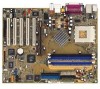
nForce2™ Ultra 400 chipset to set a new benchmark for an effective desktop platform solution. Supporting up to 3GB of system memory with PC3200/PC2700/PC2100/ PC1600 DDR SDRAM, high-resolution graphics via an AGP 8X slot, SATA, RAID, IEEE 1394, USB 2.0, and 6-channel audio features, the motherboard - Asus A7N8X-E Deluxe | A7N8X-E Deluxe User's Manual - Page 16
rate. See page 2-21. AGP 8X support The motherboard support AGP 8X (AGP 3.0) specification offering 2.12 GB/s bandwidth. See page 2-13. Dual LAN (Fast-Ethernet and Gigabit) solution The onboard Marvell® Gigabit LAN controller and Fast-Ethernet LAN controller integrated in the southbridge supply two - Asus A7N8X-E Deluxe | A7N8X-E Deluxe User's Manual - Page 17
is specifically designed for the ASUS WiFi-b™ add-on card to set up a wireless LAN environment. The ASUS WiFi-b™ add-on card bundles the Software AP (Access Point) to save the extra cost of a stand-alone AP. The card comes with user-friendly utilities and applications that allow quick connection - Asus A7N8X-E Deluxe | A7N8X-E Deluxe User's Manual - Page 18
™ The motherboard offers a new exciting feature called the ASUS POST Reporter™ to provide friendly voice messages and alerts during the Power-On Self-Tests (POST). Through an added external speaker, you will hear the messages informing you of the system boot status and causes of boot errors, if - Asus A7N8X-E Deluxe | A7N8X-E Deluxe User's Manual - Page 19
Chapter 2 This chapter lists the hardware setup procedures that you have to perform when installing system components. It includes description of the jumpers and connectors on the motherboard. Hardware information - Asus A7N8X-E Deluxe | A7N8X-E Deluxe User's Manual - Page 20
Chapter summary 2.1 Before you proceed 2-1 2.2 Motherboard overview 2-2 2.3 Central Processing Unit (CPU 2-6 2.4 System memory 2-8 2.5 Expansion slots 2-11 2.6 Jumpers 2-15 2.7 Connectors 2-18 ASUS A7N8X-E Deluxe motherboard - Asus A7N8X-E Deluxe | A7N8X-E Deluxe User's Manual - Page 21
precautions before you install motherboard components or change any motherboard settings. 1. Unplug the motherboard component. The illustration below shows the location of the onboard LED. A7N8X-E ® A7N8X-E Onboard LED PWR_LED1 ON Standby Power OFF Powered Off ASUS A7N8X-E Deluxe motherboard - Asus A7N8X-E Deluxe | A7N8X-E Deluxe User's Manual - Page 22
it. Make sure to unplug the power cord before installing or removing the motherboard. Failure to do so may cause you physical injury and damage motherboard components. 2.2.1 Placement direction When installing the motherboard, make sure that you place it into the chassis in the correct orientation - Asus A7N8X-E Deluxe | A7N8X-E Deluxe User's Manual - Page 23
SATA_EN1 CLRTC1 4Mb BIOS Super I/O USB56 COM2 CD1 FPAUDIO1 AUX1 Audio Codec MODEM1 PCI 4 SB_PWR1 PCI 5 Speech Controller WIFI SATALInk Chipset ASUS ASIC with Hardware Monitor USBPW56 GAME1 IR_CON1 SATA_RAID2 SATA_RAID1 CHASSIS1 CTRL_PANEL1 ASUS A7N8X-E Deluxe motherboard 2-3 - Asus A7N8X-E Deluxe | A7N8X-E Deluxe User's Manual - Page 24
(3-pin CPU_FSB) p. 2-15 3. USB device wake-up (3-pin USBPW12, USBPW34, USBPW56) p. 2-16 4. Gigabit LAN Setting (3-pin GLAN_SW) p. 2-16 5. Clear RTC RAM (3-pin CLRTC1) p. 2-17 6. Serial ATA setting (3-pin SATA_EN1) p. 2-17 Rear Panel Connectors 1. PS/2 mouse port 2. Fast Ethernet port (RJ-45 - Asus A7N8X-E Deluxe | A7N8X-E Deluxe User's Manual - Page 25
2-pin RESET) - ATX Power Switch (Yellow 2-pin PWRBTN) - Hard Disk Activity LED (Red 2-pin IDE_LED) p. 2-19 p. 2-19 p. 2-20 p. 2-20 p. 2-21 p. 2-22 p. 2-22 p. 2-22 p. 2-22 p. 2-23 p. 2-24 p. 2-25 p. 2-25 p. 2-25 p. 2-25 p. 2-26 p. 2-26 p. 2-27 p. 2-27 p. 2-28 ASUS A7N8X-E Deluxe motherboard 2-5 - Asus A7N8X-E Deluxe | A7N8X-E Deluxe User's Manual - Page 26
2.3 Central Processing Unit (CPU) 2.3.1 Overview The motherboard comes with a surface mount 462-pin Zero Insertion Force (ZIF) socket designed for the AMD Athlon™, AMD Athlon™ XP and AMD Duron™ processors. Take note of the marked corner (with gold triangle) on the CPU. This mark should match a - Asus A7N8X-E Deluxe | A7N8X-E Deluxe User's Manual - Page 27
CPU fits only in one correct orientation. DO NOT force the CPU into the socket to prevent bending the pins and damaging the CPU! 5. When the CPU is in place, push down the socket lever to secure the CPU. The lever clicks on the side tab to indicate that it is locked. ASUS A7N8X-E Deluxe motherboard - Asus A7N8X-E Deluxe | A7N8X-E Deluxe User's Manual - Page 28
2.4 System memory 2.4.1 Overview The motherboard comes with three (3) Double Data Rate (DDR) Dual Inline Memory Module (DIMM) sockets. The following figure illustrates the location of the sockets. 104 Pins A7N8X-E ® 80 Pins A7N8X-E 184-Pin DDR DIMM Sockets 2.4.2 Memory configurations You may - Asus A7N8X-E Deluxe | A7N8X-E Deluxe User's Manual - Page 29
- (3) Populated - Populated - - Populated Populated - - Populated Populated Populated Populated Obtain DDR400 DIMMs only from ASUS qualified vendors for better system performance. Visit the ASUS website (www.asus.com) for the latest qualified vendors list. ASUS A7N8X-E Deluxe motherboard 2-9 - Asus A7N8X-E Deluxe | A7N8X-E Deluxe User's Manual - Page 30
components. Failure to do so may cause severe damage to both the motherboard and the components. 1. Unlock a DIMM socket by pressing the retaining clips Simultaneously press the retaining clips outward to unlock the DIMM. Support the DIMM lightly with your fingers when pressing the retaining clips - Asus A7N8X-E Deluxe | A7N8X-E Deluxe User's Manual - Page 31
the software settings. 1. Turn on the system and change the necessary BIOS settings, if any. See Chapter 4 for information on BIOS setup. 2. Assign an IRQ to the card. Refer to the tables on the next page. 3. Install the software drivers for the expansion card. ASUS A7N8X-E Deluxe motherboard 2-11 - Asus A7N8X-E Deluxe | A7N8X-E Deluxe User's Manual - Page 32
5 AGP slot Serial ATA Gigabit LAN WiFi slot PCI INT A shared - - - shared - - - shared PCI INT B - - - shared - - - shared - PCI INT C - - shared - - - shared - - PCI INT D - shared - - - shared - - - When using PCI cards on shared slots, ensure that the drivers support "Share IRQ" or that the - Asus A7N8X-E Deluxe | A7N8X-E Deluxe User's Manual - Page 33
your motherboard. Install only 1.5V AGP cards on this motherboard! 3.3V AGP cards are not supported in this motherboard. AGP Card without Retention Notch A7N8X-E ® A7N8X-E Accelerated Graphics Port (AGP8X) 20-pin bay Rib (inside slot) TOP VIEW 28-pin bay Rib ASUS A7N8X-E Deluxe motherboard 2-13 - Asus A7N8X-E Deluxe | A7N8X-E Deluxe User's Manual - Page 34
support the ASUS WiFi-b™ module when available. Visit the ASUS website (www.asus.com) for product updates. The Wi-Fi slot conforms to the Institute of Electrical and Electronics Engineers (IEEE) 802.11b/g standard for wireless devices operating in the 2.4 GHz frequency band. A7N8X-E ® WIFI A7N8X - Asus A7N8X-E Deluxe | A7N8X-E Deluxe User's Manual - Page 35
333MHz, or 266MHz Front Side Bus (FSB). Set to pins 2-3 to support 200 MHz FSB only. A7N8X-E ® CPU_FSB 1 2 FSB400/333/266 (Default) 2 3 FSB200 A7N8X-E CPU FSB Jumper Setting When using an AMD Duron™ processor, change the CPU_FSB jumper setting to pins 2-3. ASUS A7N8X-E Deluxe motherboard 2-15 - Asus A7N8X-E Deluxe | A7N8X-E Deluxe User's Manual - Page 36
Set these jumpers to +5V to wake up the computer from S1 sleep mode (CPU stopped, DRAM refreshed, system running in low power mode) using the connected USB devices. Set to +5VSB to wake up from S3 and S4 sleep modes (no power to CPU, DRAM in slow refresh, power supply in reduced power mode). A7N8X - Asus A7N8X-E Deluxe | A7N8X-E Deluxe User's Manual - Page 37
data. A7N8X-E ® A7N8X-E Clear RTC RAM CLRTC1 12 23 Normal (Default) Clear CMOS 6. Serial ATA setting (3-pin SATA_EN1) This jumper enables or disables the Serial ATA controllers. A7N8X-E ® A7N8X-E SATA Setting SATA_EN1 12 Enable (Default) 23 Disable ASUS A7N8X-E Deluxe motherboard 2-17 - Asus A7N8X-E Deluxe | A7N8X-E Deluxe User's Manual - Page 38
11 10 9 8 1. PS/2 mouse port. This green 6-pin connector is for a PS/2 mouse. 2. Fast Ethernet port (RJ-45). This port allows up to 100 Mbps of data transfer rate to a Local Area Network (LAN). 3. Parallel port. This 25-pin port connects a parallel printer, a scanner, or other devices. 4. Gigabit - Asus A7N8X-E Deluxe | A7N8X-E Deluxe User's Manual - Page 39
orientation when you connect the cables. 3. The hole near the blue connector on the UltraATA cable is intentional. A7N8X-E ® A7N8X-E IDE Connectors SEC_IDE1 PRI_IDE1 NOTE: Orient the red markings (usually zigzag) on the IDE ribbon cable to PIN 1. PIN 1 ASUS A7N8X-E Deluxe motherboard 2-19 - Asus A7N8X-E Deluxe | A7N8X-E Deluxe User's Manual - Page 40
-1 pin FLOPPY1) This connector supports the provided floppy drive ribbon cable. After connecting one end to the motherboard, connect the other end to the floppy drive. (Pin 5 is removed to prevent incorrect insertion when using ribbon cables with pin 5 plug). FLOPPY1 A7N8X-E ® NOTE: Orient the red - Asus A7N8X-E Deluxe | A7N8X-E Deluxe User's Manual - Page 41
RSATA_RXN2 GND A7N8X-E ® SATA_RAID2 A7N8X-E SATA Connectors Important notes on Serial ATA solution: • Hot plug support for Serial ATA drive and connections are not available in this motherboard. • Install Windows® XP™ Service Pack 1 when using Serial ATA. ASUS A7N8X-E Deluxe motherboard 2-21 - Asus A7N8X-E Deluxe | A7N8X-E Deluxe User's Manual - Page 42
5. CPU, Power and Chassis Fan Connectors (3-pin CPU_FAN1, PWR_FAN1, CHA_FAN1) The fan connectors support cooling fans of 350mA~740mA (8.88W max.) or a total of 1A~2.22A (26.64W max.) at +12V. Connect the fan cables to the fan connectors on the motherboard, making sure that the black wire of each - Asus A7N8X-E Deluxe | A7N8X-E Deluxe User's Manual - Page 43
. The system may become unstable or may not boot up if the power is inadequate. ATXPWR1 A7N8X-E ® +3.3VDC -12.0VDC COM PS_ON# COM COM COM -5.0VDC +5.0VDC +5.0VDC A7N8X-E ATX Power Connector +3.3VDC +3.3VDC COM +5.0VDC COM +5.0VDC COM PWR_OK +5VSB +12.0VDC ASUS A7N8X-E Deluxe motherboard 2-23 - Asus A7N8X-E Deluxe | A7N8X-E Deluxe User's Manual - Page 44
. You must install the driver before you can use the USB 2.0 capability. USB+5V USB_P6USB_P6+ GND NC A7N8X-E ® A7N8X-E USB 2.0 Header USB56 1 USB+5V USB_P5USB_P5+ GND NEVER connect a 1394 cable to the USB connector. Doing so will damage the motherboard! 2-24 Chapter 2: Hardware information - Asus A7N8X-E Deluxe | A7N8X-E Deluxe User's Manual - Page 45
IE1394_1 TPA0GND TPB0+12V GND TPA0GND TPB0+12V GND A7N8X-E ® 1 1 TPA0+ GND TPB0+ +12V TPA0+ GND TPB0+ +12V A7N8X-E IEEE-1394 Connectors NEVER connect a USB cable to any of the IEEE 1394 (orange) connectors. Doing so will damage the motherboard! ASUS A7N8X-E Deluxe motherboard 2-25 - Asus A7N8X-E Deluxe | A7N8X-E Deluxe User's Manual - Page 46
-E ® FP_AUDIO MIC2 MICPWR Line out_R NC Line out_L A7N8X-E Front Panel Audio Connector 12. Digital Audio connector (6-1 pin SPDIF1) This connector is for the S/PDIF audio module to allow digital sound input/output. Connect one end of the S/PDIF audio cable to this connector and the other end to - Asus A7N8X-E Deluxe | A7N8X-E Deluxe User's Manual - Page 47
to configure the UART2 Use As parameter in the BIOS to set the UART2 to use with IR. A7N8X-E ® NC GND NC CIRRX +5VSB +5 V IRRX GND IRTX IR_CON1 SIR CIR A7N8X-E Infrared Connector Standard Infrared (SIR) Front View Back View IRTX +5V GND (NC) IRRX ASUS A7N8X-E Deluxe motherboard 2-27 - Asus A7N8X-E Deluxe | A7N8X-E Deluxe User's Manual - Page 48
IDE_LED- PWR GND Reset Ground A7N8X-E ® IDE_LED Reset SW ATX Power Switch* * Requires an ATX power supply. A7N8X-E System Panel Connectors system between ON and SLEEP, or ON and SOFT OFF, depending on the BIOS or OS settings. Pressing the power switch while in the ON mode for more than 4 - Asus A7N8X-E Deluxe | A7N8X-E Deluxe User's Manual - Page 49
Chapter 3 This chapter describes the power up sequence, the vocal POST messages and ways of shutting down the system. Powering up - Asus A7N8X-E Deluxe | A7N8X-E Deluxe User's Manual - Page 50
Chapter summary 3.1 Starting up for the first time 3-1 3.2 Powering off the computer 3-2 3.3 ASUS POST Reporter 3-4 ASUS A7N8X-E Deluxe motherboard - Asus A7N8X-E Deluxe | A7N8X-E Deluxe User's Manual - Page 51
from the time you turned on the power, the system may have failed a power-on test. Check the jumper settings and connections or call your retailer for assistance. 7. At power on, hold down to enter BIOS Setup. Follow the instructions in Chapter 4. ASUS A7N8X-E Deluxe motherboard 3-1 - Asus A7N8X-E Deluxe | A7N8X-E Deluxe User's Manual - Page 52
turn off after Windows shuts down. If you are using Windows XP, click the Start Windows shuts down. 3.2.2 Using the dual function power switch While the system is ON, pressing the power switch for less than 4 seconds puts the system to sleep mode or to soft-off mode, depending on the BIOS setting - Asus A7N8X-E Deluxe | A7N8X-E Deluxe User's Manual - Page 53
one of the PCI slots, or a 1.5V AGP card into the AGP slot. • Make sure that your VGA/AGP card is not defective. • Check your CPU settings in BIOS and make sure you only set to the recommended settings. See section "4.4 Advanced menu." ASUS A7N8X-E Deluxe motherboard 3-3 - Asus A7N8X-E Deluxe | A7N8X-E Deluxe User's Manual - Page 54
sure that your CPU fan supports the fan speed detection function. CPU voltage out of range • Check your power supply and make sure it is not defective. • Call ASUS technical support for assistance. See the "ASUS contact information" on the inside front cover of this manual. System completed Power - Asus A7N8X-E Deluxe | A7N8X-E Deluxe User's Manual - Page 55
software from the utilities menu of the support CD. See section "5.2.3 Utilities menu" for details. To avoid conflicts, do not run the Winbond Voice Editor while running the ASUS PC Probe. , then click the Play button. The default language setting is English. ASUS A7N8X-E Deluxe motherboard 3-5 - Asus A7N8X-E Deluxe | A7N8X-E Deluxe User's Manual - Page 56
have a corresponding message due to file size constraints. 3. Click on the Write button to update the EEPROM. 4. Click Yes on the confirmation window that appears. The next time you boot your computer, the POST messages are announced in the language that you selected . 3-6 Chapter 3: Powering - Asus A7N8X-E Deluxe | A7N8X-E Deluxe User's Manual - Page 57
make your messages as short as possible. 3. Use a recording software, such as Windows Recorder, to record your messages. 4. Save the messages as wave files (.WAV). File window. 6. Copy the wave files that you recorded to the database. Close the window when done. ASUS A7N8X-E Deluxe motherboard 3-7 - Asus A7N8X-E Deluxe | A7N8X-E Deluxe User's Manual - Page 58
Editor screen, then on the Edit button. The Event Sound Editor window appears. 8. Locate and select your wave file for steps 7 to 9 for the other events. 11. When done, click the Save button. A window appears prompting you to save your configuration. 12. Type a file name with a .flh extension, then - Asus A7N8X-E Deluxe | A7N8X-E Deluxe User's Manual - Page 59
Chapter 4 This chapter tells how to change the system settings through the BIOS Setup menus. Detailed descriptions of the BIOS parameters are also provided. BIOS setup - Asus A7N8X-E Deluxe | A7N8X-E Deluxe User's Manual - Page 60
Chapter summary 4.1 Managing and updating your BIOS 4-1 4.2 BIOS Setup program 4-7 4.3 Main Menu 4-10 4.4 Advanced Menu 4-14 4.5 Security Menu 4-27 4.6 Hardware Monitor Menu 4-29 4.7 Exit Menu 4-30 ASUS A7N8X-E Deluxe motherboard - Asus A7N8X-E Deluxe | A7N8X-E Deluxe User's Manual - Page 61
MS-DOS startup disk from the format options field, then click Start. OR If you are using Windows™ 98SE/ME/2000, select Full option button from the format type, then click Start. 2. Copy the original (or the latest) motherboard BIOS to the bootable floppy disk. ASUS A7N8X-E Deluxe motherboard 4-1 - Asus A7N8X-E Deluxe | A7N8X-E Deluxe User's Manual - Page 62
launch the AwardBIOS flash utility. Write down the BIOS file name to a piece of paper. You need to type the exact BIOS file name at the prompt. 1. Visit the ASUS website (www.asus.com) to download the latest BIOS file for your motherboard and rename it to A7N8X-E.ROM. Save the BIOS file to a floppy - Asus A7N8X-E Deluxe | A7N8X-E Deluxe User's Manual - Page 63
to save the previous BIOS to a separate file. Type a file name for the old bios and then press . The AWDFLASH program backs-up the file. 7. AWDFLASH proceeds to check the new BIOS file and asks the user to program (flash) the new BIOS file to the motherboard. ASUS A7N8X-E Deluxe motherboard 4-3 - Asus A7N8X-E Deluxe | A7N8X-E Deluxe User's Manual - Page 64
. NOTE: Do not shut off system power or unplug the supply during the flash process. 9. The BIOS flashes and displays the results. Press to restart. Updating BIOS via Bootable Floppy Disk 1. Boot from the floppy disk. 2. At the A:\ prompt, type C:\ then press . 3. At the C:\ prompt, type - Asus A7N8X-E Deluxe | A7N8X-E Deluxe User's Manual - Page 65
4.1.3 ASUS Update The ASUS Update is a utility that allows you to update the motherboard BIOS in Windows® environment. This utility is available in the support CD that comes with the motherboard package. ASUS Update requires an Internet connection either through a network or an Internet Service - Asus A7N8X-E Deluxe | A7N8X-E Deluxe User's Manual - Page 66
4. From the FTP site, select the BIOS version that you wish to download. Click Next. 5. Follow the instructions on the succeeding screens to complete the update process. If you selected the option to update the BIOS from a file, a window pops up prompting you to locate the file. Select the file, - Asus A7N8X-E Deluxe | A7N8X-E Deluxe User's Manual - Page 67
Menu. See section "4.7 Exit Menu." The BIOS setup screens shown in this chapter are for reference purposes only, and may not exactly match what you see on your screen. Visit the ASUS website (www.asus.com) to download the latest product and BIOS information. ASUS A7N8X-E Deluxe motherboard 4-7 - Asus A7N8X-E Deluxe | A7N8X-E Deluxe User's Manual - Page 68
the following main items: Main For changing the basic system configuration Advanced For changing the advanced system settings Security Use this menu to set the Supervisor and User passwords. Hardware Monitor Monitor the status of vital components, including voltages and fan speeds. Exit For - Asus A7N8X-E Deluxe | A7N8X-E Deluxe User's Manual - Page 69
items. The other items (Advanced, Power, Boot, and Exit) on the menu bar have their can not select an item that is not user-configurable. A configurable field is enclosed in Pop-up window Select a menu item then press Enter to display a pop-up window with the ASUS A7N8X-E Deluxe motherboard 4-9 - Asus A7N8X-E Deluxe | A7N8X-E Deluxe User's Manual - Page 70
BIOS menu screen" for information on the menu screen items and how to navigate through them. 4.3.1 System Time [xx:xx:xxxx] This item allows you to set in.] [2.88M, 3.5 in.] 4.3.4 Halt On [All Errors] This field sets the system to halt on errors according to the system functions specified in each - Asus A7N8X-E Deluxe | A7N8X-E Deluxe User's Manual - Page 71
setup BIOS may detect incorrect parameters. In these cases, select [Manual] to manually enter the IDE hard disk drive parameters. If no drive is installed or if you are removing a drive and not replacing it, select [None]. Configuration options: [None] [Auto [Manual] ASUS A7N8X-E Deluxe motherboard - Asus A7N8X-E Deluxe | A7N8X-E Deluxe User's Manual - Page 72
hard disk. [Manual] & [CHS] Settings Manually enter the number of cylinders, heads and sectors per track for the drive. Refer to the drive documentation or on the drive label for this information. After entering the IDE hard disk drive information into BIOS, use a disk utility, such as FDISK - Asus A7N8X-E Deluxe | A7N8X-E Deluxe User's Manual - Page 73
This field configures the number of sectors per track. Refer to the drive documentation to determine the correct value. To make changes to this field, set the Type field to [User Type HDD] and the Translation Method field to [Manual]. ASUS A7N8X-E Deluxe motherboard 4-13 - Asus A7N8X-E Deluxe | A7N8X-E Deluxe User's Manual - Page 74
4.4 Advanced menu The Advanced menu items allow you to change the settings for the CPU and other system devices. Take caution when changing the settings of the Advanced menu items. Incorrect field values may cause the system to malfunction. 4-14 Chapter 4: BIOS Setup - Asus A7N8X-E Deluxe | A7N8X-E Deluxe User's Manual - Page 75
[Disabled] CPU Level 2 Cache [Enabled] This field enables or disables the level 2 cache. Configuration options: [Enabled] [Disabled] Quick Power On Self Test [Enabled] This field enables or disables the power on test. Configuration options: [Enabled] [Disabled] ASUS A7N8X-E Deluxe motherboard 4-15 - Asus A7N8X-E Deluxe | A7N8X-E Deluxe User's Manual - Page 76
] [HDD-0] [SCSI] [CDROM] [HDD-1] [HDD-2] [HDD-3] [ZIP] [USBFDD] [USB-ZIP] [USB-CDROM] [USB-HDD] [LAN] [Disabled] Second Boot Device [HDD] This field sets the priority of the second boot device. By default, the system boots up on the hard disk driver if the floppy drive is not present. Configuration - Asus A7N8X-E Deluxe | A7N8X-E Deluxe User's Manual - Page 77
enables or disables the ASUS POST ReporterTM feature. Configuration options: [Enabled] [Disabled] POST Complete Report [Enabled] This field enables or disables display of the Power On Self Test (POST) complete report. Configuration options: [Enabled] [Disabled] ASUS A7N8X-E Deluxe motherboard 4-17 - Asus A7N8X-E Deluxe | A7N8X-E Deluxe User's Manual - Page 78
MHz] [207 MHz] [211 MHz] [300 MHz] CPU Frequency Multiple Setting [Auto] This field sets the frequency multiple between the CPU's internal frequency (CPU speed) and external frequency. Set this field in conjunction with CPU Frequency (MHz) to match the speed of the CPU. 4-18 Chapter 4: BIOS Setup - Asus A7N8X-E Deluxe | A7N8X-E Deluxe User's Manual - Page 79
to [User Defined], the next four fields can be set manually. Set to [Aggressive] for higher performance. Use default [Optimal] to use most stable settings. Configuration options: [Optimal] [Aggressive] [User Defined] SDRAM Active Precharge Delay [7] Row-active delay. ASUS A7N8X-E Deluxe motherboard - Asus A7N8X-E Deluxe | A7N8X-E Deluxe User's Manual - Page 80
is set to [Manual], this field permits selection of specific CPU core voltages. This field is not accessible if the above CPU VCore Setting parameter is set to [Auto]. Configuration options: [1.100V] [1.125V] ... [1.825] [1.850V] Graphics Aperture Size [64M] This field sets the size of mapped memory - Asus A7N8X-E Deluxe | A7N8X-E Deluxe User's Manual - Page 81
[1.7V] AGP 8X Support [Enabled] This field enables or disables the AGP 8X support. Configuration options: [Disable] [Enable] AGP Fast Write Capability [Enabled] This field enables or disables the AGP Fastwrite function. Configuration options: [Disable] [Enable] ASUS A7N8X-E Deluxe motherboard 4-21 - Asus A7N8X-E Deluxe | A7N8X-E Deluxe User's Manual - Page 82
options: [Enabled] [Disabled] USB Legacy Mouse Support [Disabled] This field sets support for USB legacy mouse. The USB legacy mouse is disabled by default. Enable this field to use a USB legacy mouse. Configuration options: [Enabled] [Disabled] Onboard AC97 Audio Controller [Auto] This field - Asus A7N8X-E Deluxe | A7N8X-E Deluxe User's Manual - Page 83
[ECP] [ECP +EPP] ECP DMA Select [3] This field sets the parallel port DMA channel for the selected ECP mode. The default setting is 3. This selection is available only if you select [ECP] or [ECP+EPP] in Parallel Port Mode above. Configuration options: [1] [3] ASUS A7N8X-E Deluxe motherboard 4-23 - Asus A7N8X-E Deluxe | A7N8X-E Deluxe User's Manual - Page 84
I/O port to 330 by default. Configuration options: [Disabled] [330] [300] Onboard MIDI IRQ [10] This field sets the IRQ address of the MIDI port to 10 by default. Configuration options: [5] [10] 4.4.4 Power Management Setup ACPI Suspend to RAM [Disabled] This field enables or disables suspension to - Asus A7N8X-E Deluxe | A7N8X-E Deluxe User's Manual - Page 85
enables Wake-On-LAN from soft-off mode. The default disables this option. Configuration options: [Enabled] [Disabled] Wake-Power Up On Ext. Modem [Disabled] This field allows either settings of [Enabled] . Configuration options: [Disabled] [Any KEY] [Power Key] ASUS A7N8X-E Deluxe motherboard 4-25 - Asus A7N8X-E Deluxe | A7N8X-E Deluxe User's Manual - Page 86
Resources Controlled By [Auto(ESCD)] This field sets control over the IRQ resources by the automatic (ESCD) system or manual assignment of IRQ channels. The default enables automatic (ESCD) control. Configuration options: [Auto(ESCD)] [Manual] Selecting Manual access the IRQ Resources sub-menu; see - Asus A7N8X-E Deluxe | A7N8X-E Deluxe User's Manual - Page 87
only Security Option System System Supervisor Password User Password None None • A password is required when booting and to access the BIOS setup. • All items can be modified. • A password is required to access the BIOS setup. • All items can be modified. ASUS A7N8X-E Deluxe motherboard 4-27 - Asus A7N8X-E Deluxe | A7N8X-E Deluxe User's Manual - Page 88
Set Supervisor Password / Set User Password To set set to [Disabled]. Forgot the password? If you forget a password, you can clear it by erasing the CMOS Real Time Clock (RTC) RAM. The RAM data containing the password information is powered by the onboard button cell battery. See section "2.7 Jumpers - Asus A7N8X-E Deluxe | A7N8X-E Deluxe User's Manual - Page 89
or disable the ASUS Q-Fan feature that smartly adjusts the fan speeds for more efficient system operation. When this field is set to [Enabled], set the appropriate Fan Speed Ratio and Speed Up/Down Response Time. Configuration options: [Disabled] [Enabled] ASUS A7N8X-E Deluxe motherboard 4-29 - Asus A7N8X-E Deluxe | A7N8X-E Deluxe User's Manual - Page 90
Select a higher ratio if you installed additional devices and the system requires more ventilation. This item is required to be set when the Q-Fan Control field is [Enabled]. Configuration options: [10/15] [11/15] [12/15] [13/15 or from the legend bar to exit. 4-30 Chapter 4: BIOS Setup - Asus A7N8X-E Deluxe | A7N8X-E Deluxe User's Manual - Page 91
CMOS RAM. The CMOS RAM is sustained by an onboard backup battery and stays on even when the PC is turned off. When you select this option, a confirmation window appears. , a confirmation window appears. Select [Yes] to save any changes to the non-volatile RAM. ASUS A7N8X-E Deluxe motherboard 4-31 - Asus A7N8X-E Deluxe | A7N8X-E Deluxe User's Manual - Page 92
4-32 Chapter 4: BIOS Setup - Asus A7N8X-E Deluxe | A7N8X-E Deluxe User's Manual - Page 93
Chapter 5 This chapter describes the contents of the support CD that comes with the motherboard package. Software support - Asus A7N8X-E Deluxe | A7N8X-E Deluxe User's Manual - Page 94
5.2 Support CD infomation 5-1 5.3 NVIDIA® nForce control panel 5-3 5.4 NVIDIA® NVSwap 1.0 Utility 5-11 5.5 RAID 0 / RAID 1 configurations 5-13 5.6 Onboard Marvell Gigabit LAN drivers for Windows® 98SE/ME 5-16 5.7 Marvell® Virtual Cable Tester Technology .. 5-17 ASUS A7N8X-E Deluxe motherboard - Asus A7N8X-E Deluxe | A7N8X-E Deluxe User's Manual - Page 95
software and several utility drivers that enhance the motherboard features. The contents of the support CD are subject to change at any time without notice. Visit the ASUS website for updates. 5.2.1 Running the support CD To begin using the support CD, simply insert the CD into your CD-ROM drive - Asus A7N8X-E Deluxe | A7N8X-E Deluxe User's Manual - Page 96
. USB 2.0 Driver This item installs the USB 2.0 driver to upgrade your USB 1.1 ports to USB 2.0. Silicon Image Serial ATA Utility This item installs the software utility to monitor. A. For Windows 98SE users, perform the following steps before installing the NVIDIA nForce Drivers from support CD - Asus A7N8X-E Deluxe | A7N8X-E Deluxe User's Manual - Page 97
. ASUS Update This program allows you to download the latest version of the BIOS from the ASUS website. See section "4.1.3 ASUS Update" on page 4-5. Before using the ASUS Update, make sure that you have an Internet connection so you can connect to the ASUS website. ASUS A7N8X-E Deluxe motherboard - Asus A7N8X-E Deluxe | A7N8X-E Deluxe User's Manual - Page 98
Screen display and utilities option may not be the same for other operating system versions. 5.2.4 ASUS Contact Information Clicking the ASUS Contact Information tab displays as stated. You may also find this information in the inside front cover of this user guide. 5-4 Chapter 5: Software support - Asus A7N8X-E Deluxe | A7N8X-E Deluxe User's Manual - Page 99
motherboard and the contents of the support CD. Click an icon to display the specified information. Motherboard Info The window displays the general specifications of the A7N8X-E Deluxe motherboard. Browse this CD The window displays the support CD contents in graphical format. ASUS A7N8X-E Deluxe - Asus A7N8X-E Deluxe | A7N8X-E Deluxe User's Manual - Page 100
Technical Support Form The window displays the ASUS Technical Support Request Form that you have to fill up when requesting technical support. Filelist The window displays the contents of the support CD and a brief description of each in text format. 5-6 Chapter 5: Software support - Asus A7N8X-E Deluxe | A7N8X-E Deluxe User's Manual - Page 101
from all your computer controlled audio systems. Follow the installation wizard to install the NVIDIA nForce drivers from the motherboard support CD. Use 4-channel or 6-channel specialty features. A wizard is also available to help guide you through the process. ASUS A7N8X-E Deluxe motherboard 5-7 - Asus A7N8X-E Deluxe | A7N8X-E Deluxe User's Manual - Page 102
audio module allows digital instead of analog sound sound (primarily older 4 channel PC speaker systems) • LFE Crossover Frequency - Adjusts the amount of bass signal removed from the main speakers and sent specifically to the subwoofer output (increment in hertz). 5-8 Chapter 5: Software support - Asus A7N8X-E Deluxe | A7N8X-E Deluxe User's Manual - Page 103
Applications tab is used to put audio application shortcuts. It is just a quick way to get at their favorite audio applications from within the Control Panel. Applications can be added or removed by using the buttons in the lower right hand corner of this page. ASUS A7N8X-E Deluxe motherboard 5-9 - Asus A7N8X-E Deluxe | A7N8X-E Deluxe User's Manual - Page 104
DirectX version, and in "Advanced" mode the DSP and voice utilization. This is the first place to look when you are verifying what drivers you are running and the last place to look when you want to know what is going on at the lower levels of the APU. 5-10 Chapter 5: Software support - Asus A7N8X-E Deluxe | A7N8X-E Deluxe User's Manual - Page 105
on the selected speaker for up to 5 seconds before returning to the cycling pattern. For 6.1 audio channel setting, there is no need to perform the following tasks. Simply connect the Rear Speaker to the purple jack and the Center/Subwoofer to the orange jack. ASUS A7N8X-E Deluxe motherboard 5-11 - Asus A7N8X-E Deluxe | A7N8X-E Deluxe User's Manual - Page 106
motherboard will not accept a Line In source. Changing this setting has the same effect as selecting or deselecting the "Rear Speakers connected to Line In" option in the Windows sound coming for the subwoofer when the center speaker is highlighted, and vise versa. 5-12 Chapter 5: Software support - Asus A7N8X-E Deluxe | A7N8X-E Deluxe User's Manual - Page 107
SATA RAID User's Manual found in "\Drivers\SATA\SATARaid_Manual_Rev092.PDF" of the motherboard support CD. 5.5.1 Install the hard disks The Sil 3112A chipset supports Serial ATA hard disk drives. For optimal performance, install identical drives of the same model and capacity when creating RAID sets - Asus A7N8X-E Deluxe | A7N8X-E Deluxe User's Manual - Page 108
more detailed information on jumper settings. 6. Proceed to 5.9.2 for the next procedure. 5.5.2 Creating and Deleting RAID sets Creating and deleting RAID sets is a built-in function found in the BIOS. The following sub-sections describes how to use the RAID Configuration Utility. Loading the RAID - Asus A7N8X-E Deluxe | A7N8X-E Deluxe User's Manual - Page 109
RAID set to function properly, this old metadata must be first overwritten with the new metadata. To resolve this, select "Resolve Conflict" and the correct metadata, including the correct drive connection information, will be written to the replacement disk. ASUS A7N8X-E Deluxe motherboard 5-15 - Asus A7N8X-E Deluxe | A7N8X-E Deluxe User's Manual - Page 110
systems, you need to install the onboard LAN drivers from the support CD. Installing onboard LAN drivers Follow these instructions to install the onboard LAN drivers for Windows 98SE/ME. 1. Boot your computer. 2. Click the Start button. Select Settings, then Control Panel. 3. Double-click the - Asus A7N8X-E Deluxe | A7N8X-E Deluxe User's Manual - Page 111
™ (VCT) feature is supported in Windows® XP™ and Windows® 2000™ operating systems only. • The Virtual Cable Tester™ (VCT) feature works in Gigabit LAN only. • The Run button on the VCT Tester dialogue box is disabled if no problem is detected on the network. ASUS A7N8X-E Deluxe motherboard 5-17 - Asus A7N8X-E Deluxe | A7N8X-E Deluxe User's Manual - Page 112
5-18 Chapter 5: Software support - Asus A7N8X-E Deluxe | A7N8X-E Deluxe User's Manual - Page 113
FLOPPY1 QUICK REFERENCE CARD A7N8X-E ASUS Motherboard Refer to the Quick Setup Guide when installing components or CPU_FAN1 devices for the items indicated in this reference card. SEC_IDE1 PRI_IDE1 PWR_FAN1 CHA_FAN1 A7N8X-E ® Keyboard Lock Speaker Power LED Connector PLED+ PLEDKeylock - Asus A7N8X-E Deluxe | A7N8X-E Deluxe User's Manual - Page 114
-
 1
1 -
 2
2 -
 3
3 -
 4
4 -
 5
5 -
 6
6 -
 7
7 -
8
-
9
-
10
-
11
-
12
-
13
-
14
-
15
-
16
-
17
-
18
-
19
-
20
-
21
-
22
-
23
-
24
-
25
-
26
-
27
-
28
-
29
-
30
-
31
-
32
-
33
-
34
-
35
-
36
-
37
-
38
-
39
-
40
-
41
-
42
-
43
-
44
-
45
-
46
-
47
-
48
-
49
-
50
-
51
-
52
-
53
-
54
-
55
-
56
-
57
-
58
-
59
-
60
-
61
-
62
-
63
-
64
-
65
-
66
-
67
-
68
-
69
-
70
-
71
-
72
-
73
-
74
-
75
-
76
-
77
-
78
-
79
-
80
-
81
-
82
-
83
-
84
-
85
-
86
-
87
-
88
-
89
-
90
-
91
-
92
-
93
-
94
-
95
-
96
-
97
-
98
-
99
-
100
-
101
-
102
-
103
-
104
-
105
-
106
-
107
-
108
-
109
-
110
-
111
-
112
-
113
-
114
 |
 |

Motherboard
A7N8X-E
Deluxe
User Guide