Asus A7N8X-VM 400 Motherboard DIY Troubleshooting Guide
Asus A7N8X-VM 400 Manual
 |
View all Asus A7N8X-VM 400 manuals
Add to My Manuals
Save this manual to your list of manuals |
Asus A7N8X-VM 400 manual content summary:
- Asus A7N8X-VM 400 | Motherboard DIY Troubleshooting Guide - Page 1
Motherboard A7N8X-VM/400 User Guide - Asus A7N8X-VM 400 | Motherboard DIY Troubleshooting Guide - Page 2
written permission of ASUSTeK COMPUTER INC. ("ASUS"). Product warranty or service will not be extended if: (1) the product is repaired, modified the serial number of the product is defaced or missing. ASUS PROVIDES THIS MANUAL "AS IS" WITHOUT WARRANTY OF ANY KIND, EITHER EXPRESS OR IMPLIED, - Asus A7N8X-VM 400 | Motherboard DIY Troubleshooting Guide - Page 3
information vi About this guide vii A7N8X-VM/400 specification summary viii Chapter 1: Product introduction 1.1 Welcome 1-2 1.2 Package contents 1-2 1.3 Special features 1-2 1.4 Motherboard components 1-4 1.5 Motherboard layout 1-7 1.6 Motherboard installation 1-8 1.6.1 Placement direction - Asus A7N8X-VM 400 | Motherboard DIY Troubleshooting Guide - Page 4
Slave 2-11 2.3.2 System Information 2-12 2.4 Advanced menu 2-13 2.4.1 Chipset 2-13 2.4.2 Onboard Devices Configuration 2-14 2.4.3 PCIPnP 2-16 2.5 Power Software support 3.1 Installing an operating system 3-2 3.2 Support CD information 3-2 3.2.1 Running the support CD 3-2 3.2.2 Drivers menu - Asus A7N8X-VM 400 | Motherboard DIY Troubleshooting Guide - Page 5
. This equipment generates, uses and can radiate radio frequency energy and, if not installed and used in accordance with manufacturer's instructions, may cause harmful interference to radio communications. However, there is no guarantee that interference will not occur in a particular installation - Asus A7N8X-VM 400 | Motherboard DIY Troubleshooting Guide - Page 6
Contact a qualified service technician or your retailer. Operation safety • Before installing the motherboard and adding devices on it, carefully read all the manuals that came with . • If you encounter technical problems with the product, contact a qualified service technician or your retailer. vi - Asus A7N8X-VM 400 | Motherboard DIY Troubleshooting Guide - Page 7
certain tasks properly, take note of the following symbols used throughout this guide. WARNING: Information to prevent injury to yourself when trying to complete a and for product and software updates. 1. ASUS websites The ASUS websites worldwide provide updated information on ASUS hardware and - Asus A7N8X-VM 400 | Motherboard DIY Troubleshooting Guide - Page 8
A7N8X-VM/400 specifications summary CPU Chipset Front Side Bus Memory Expansion slots Storage Graphics Audio LAN Hardware monitoring Rear panel ports Internal connectors Socket A for AMD Athlon™ XP 2700 MHz+ processors NVIDIA® nForce2 IGP North bridge NVIDIA® nForce2 MCP South bridge 400/333/266 - Asus A7N8X-VM 400 | Motherboard DIY Troubleshooting Guide - Page 9
2.2, USB 2.0 Manageability DMI 2.0, WOL by PME, WOR by PME, WO_USB, WO_KB/MS Support CD contents Device drivers ASUS PC Probe ASUS Update ASUS Screen Saver Adobe Acrobat Reader Anti-Virus Utility Accessories ASUS A7N8X-VM/400 series support CD UltraDMA133 cable FDD cable I/O shield User guide - Asus A7N8X-VM 400 | Motherboard DIY Troubleshooting Guide - Page 10
- Asus A7N8X-VM 400 | Motherboard DIY Troubleshooting Guide - Page 11
Chapter 1 This chapter describes the features of the motherboard. It includes brief descriptions of the motherboard components, and illustrations of the layout, jumper settings, and connectors. Product introduction - Asus A7N8X-VM 400 | Motherboard DIY Troubleshooting Guide - Page 12
in ASUS A7N8X-VM/400 series support CD 40-pin 80-conductor ribbon cable for UltraDMA133 IDE drives Ribbon cable for a 3.5-inch floppy drive Bag of extra jumper caps I/O shield User guide 1.3 Special features 400 MHz FSB support The motherboard comes with a Socket 462 that supports the latest 400 MHz - Asus A7N8X-VM 400 | Motherboard DIY Troubleshooting Guide - Page 13
Digital video output support The DVO interface feature of this motherboard allows you to enjoy simultaneous digital display and TV output with the separately purchased ASUS AGP-NV-DVI and ASUS AV/S TV-out cards. See details on pages 1-13, 1-20, and 2-14. ASUS A7N8X-VM/400 motherboard user guide - Asus A7N8X-VM 400 | Motherboard DIY Troubleshooting Guide - Page 14
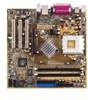
components Before you install the motherboard, learn about its major components and available features to facilitate the installation and future upgrades. Refer to the succeeding pages for the component descriptions. 12 - Asus A7N8X-VM 400 | Motherboard DIY Troubleshooting Guide - Page 15
channel. 11 AGP slot. The Accelerated Graphics Port (AGP) slot supports 1.5 V AGP 8X/4X mode graphics cards for 3D graphics applications. The AGP slot also supports digital visual interface (DVI) cards for digital display on LCD monitors and projectors. ASUS A7N8X-VM/400 motherboard user guide 1-5 - Asus A7N8X-VM 400 | Motherboard DIY Troubleshooting Guide - Page 16
onboard audio solution for PC multimedia systems. 13 PCI slots. These 32-bit PCI 2.2 expansion slots support bus master PCI cards like SCSI and LAN cards. 14 LAN controller. The Realtek 8201BL LAN PHY Fast Ethernet controller allows connection to a Local Area Network (LAN) through a network hub - Asus A7N8X-VM 400 | Motherboard DIY Troubleshooting Guide - Page 17
nVidia nForce2 IGP CHA_FAN A7N8X-VM Accelerated Graphics Port (AGP8X1) PCI 1 FPAUDIO Audio Codec PCI 2 SPDIF1 PCI 3 23 45 Super I/O CR2032 3V Lithium Cell CMOS Power nVidia MCP CLRTC1 4Mb BIOS CHASSIS1 COM2 USBPW56 GAME1 USB56 PANEL1 ASUS A7N8X-VM/400 motherboard user guide 1-7 - Asus A7N8X-VM 400 | Motherboard DIY Troubleshooting Guide - Page 18
uses the Micro ATX form factor. Unplug the power cord before installing the motherboard. Failure to do so may cause you physical injury and damage to motherboard components. 1.6.1 Placement direction When installing the motherboard, make sure that you place it into the chassis in the correct - Asus A7N8X-VM 400 | Motherboard DIY Troubleshooting Guide - Page 19
shut down the system and unplug the power cable before removing or plugging in any motherboard component. The illustration below shows the location of the onboard LED. SB_PWR1 A7N8X-VM ON Standby Power A7N8X-VM/400 Onboard LED OFF Powered Off ASUS A7N8X-VM/400 motherboard user guide 1-9 - Asus A7N8X-VM 400 | Motherboard DIY Troubleshooting Guide - Page 20
/333/266 MHz bus speeds. AMD Athlon™ XP processors offer gigahertz speeds to support all the latest computing platforms and applications. A7N8X-VM CPU NOTCH TO INNER CORNER AMD™ CPU LOCK LEVER CPU NOTCH A7N8X-VM/400 Socket 462 Each AMD CPU has a "marked" corner. This corner is usually indicated - Asus A7N8X-VM 400 | Motherboard DIY Troubleshooting Guide - Page 21
256 MB, 512 MB and 1 GB. The motherboard supports dual-channel memory architecture when you install two DDR DIMMs. A7N8X-VM 104 Pins 80 Pins A7N8X-VM/400 184-Pin DDR DIMM Sockets Installing a DIMM a DIMM into a socket to avoid damaging the DIMM. ASUS A7N8X-VM/400 motherboard user guide 1-11 - Asus A7N8X-VM 400 | Motherboard DIY Troubleshooting Guide - Page 22
Onboard LAN 10* USB Universal Host Controller 11* Onboard VGA 12* PS/2 Compatible Mouse Port 13 Numeric Data Processor 14* Ultra ATA Controller 15* Secondary Ultra ATA Controller *These IRQs are usually available for ISA or PCI devices. IRQ assignments for this motherboard A B PCI - Asus A7N8X-VM 400 | Motherboard DIY Troubleshooting Guide - Page 23
10.3 PCI slots Three 32-bit PCI slots are available on the motherboard. The slots support PCI cards such as LAN card, SCSI card, USB card, and other cards that comply with PCI specifications. This figure shows a typical PCI card installed into a slot. ASUS A7N8X-VM/400 motherboard user guide 1-13 - Asus A7N8X-VM 400 | Motherboard DIY Troubleshooting Guide - Page 24
motherboard. 1. USB device wake-up (3-pin USBPW12, USBPW34, USBPW56) Set these jumpers to +5V to wake up the computer from S1 sleep mode (CPU stopped, DRAM refreshed, system running in low power mode) using the connected USB sleep mode. USBPW34 12 23 A7N8X-VM A7N8X-VM/400 USB Device Wake Up +5V - Asus A7N8X-VM 400 | Motherboard DIY Troubleshooting Guide - Page 25
powered by the onboard button battery cell. To erase the RTC RAM: 1. Turn OFF the computer and unplug the power cord. boot process and enter BIOS setup to re-enter data. A7N8X-VM CLRTC1 12 23 Normal A7N8X-VM/400 Clear RTC RAM (Default) Clear CMOS ASUS A7N8X-VM/400 motherboard user guide 1-15 - Asus A7N8X-VM 400 | Motherboard DIY Troubleshooting Guide - Page 26
) on the IDE ribbon cable to PIN 1. SEC_IDE PRI_IDE A7N8X-VM/400 IDE Connectors PIN 1 2. Floppy disk drive connector (34-1 pin FLOPPY1) This connector supports the provided floppy drive ribbon cable. After connecting one end to the motherboard, connect the other end to the floppy drive. (Pin - Asus A7N8X-VM 400 | Motherboard DIY Troubleshooting Guide - Page 27
cable to this connector, then mount the USB/GAME port module to an open slot in the chassis. USB+5V USB_P6USB_P6+ GND NC A7N8X-VM USB+5V USB_P5USB_P5+ GND A7N8X-VM/400 USB 2.0 Header USB56 1 The USB/GAME port module is purchased separately. ASUS A7N8X-VM/400 motherboard user guide 1-17 - Asus A7N8X-VM 400 | Motherboard DIY Troubleshooting Guide - Page 28
A7N8X-VM A7N8X-VM/400 Game Connector GAME1 The USB/GAME port module is purchased separately. 6. CPU and chassis fan connectors (3-pin CPU_FAN1, CHA_FAN) The fan connectors support cooling fans of 350 mA ~ 740 mA (8.88 W max). Connect the fan cable plugs to the fan connectors on the motherboard - Asus A7N8X-VM 400 | Motherboard DIY Troubleshooting Guide - Page 29
FP_AUDIO) This connects the front panel audio module that allows convenient connection and control of audio devices. AGND +5VA BLINE_OUT_R BLINE_OUT_L MIC2 MICPWR Line out_R NC Line out_L A7N8X-VM FP_AUDIO A7N8X-VM/400 Front Panel Audio Connector ASUS A7N8X-VM/400 motherboard user guide 1-19 - Asus A7N8X-VM 400 | Motherboard DIY Troubleshooting Guide - Page 30
CD1, AUX1) These connectors allow you to receive stereo audio input from sound sources such as a CD-ROM, TV tuner or MPEG card. A7N8X-VM AUX1 (White) CD1 (Black) Left Audio Channel Ground Right Audio Channel A7N8X-VM/400 Internal Audio Connectors 10. TV-out connector (6-1 pin U46) This connects - Asus A7N8X-VM 400 | Motherboard DIY Troubleshooting Guide - Page 31
purchased separately. SPDIF_OUT +5V SPDIF_IN GND GND A7N8X-VM SPDIF1 1 A7N8X-VM/400 Digital Audio Connector When you input sound for S/PDIF IN chassis. A7N8X-VM COM2 PIN 1 A7N8X-VM/400 Serial Connector The serial port module is purchased separately. ASUS A7N8X-VM/400 motherboard user guide 1- - Asus A7N8X-VM 400 | Motherboard DIY Troubleshooting Guide - Page 32
Ground Speaker +5V IDELED ExtSMI# Ground PWR Ground Reset Ground A7N8X-VM A7N8X-VM/400 Panel Connectors IDE LED SMI Lead Reset SW ATX Power Switch* the system between ON and SLEEP, or ON and SOFT OFF, depending on the BIOS or OS settings. When the system is on, pressing the power switch for more - Asus A7N8X-VM 400 | Motherboard DIY Troubleshooting Guide - Page 33
Chapter 2 This chapter tells how to change system settings through the BIOS Setup menus. Detailed descriptions of the BIOS parameters are also provided. BIOS information - Asus A7N8X-VM 400 | Motherboard DIY Troubleshooting Guide - Page 34
original motherboard BIOS using the AFUDOS or the ASUS Update utilities. • A working BIOS file for this motherboard is in the support CD. Use this file only when you do not have a copy of the original motherboard BIOS file in a floppy disk. • Visit the ASUS website and download the latest BIOS file - Asus A7N8X-VM 400 | Motherboard DIY Troubleshooting Guide - Page 35
the file. A:\>afudos /oMYBIOS03.rom AMI Firmware Update Utility - Version 1.10 Copyright (C) 2002 American Megatrends, Inc. All rights reserved. Reading flash ..... done A:\> When the BIOS copy process is complete, the utility returns to the DOS prompt. ASUS A7N8X-VM/400 motherboard user guide 2-3 - Asus A7N8X-VM 400 | Motherboard DIY Troubleshooting Guide - Page 36
2.1.3 Using AFUDOS to update the BIOS Update the BIOS only if you are sure that updating revision will solve your problems. Careless updating may result to more problems with the motherboard! 1. Download an updated ASUS BIOS file from the Internet (www.asus.com), then save the file to the bootable - Asus A7N8X-VM 400 | Motherboard DIY Troubleshooting Guide - Page 37
system while updating the BIOS! Doing so may cause system boot failure! User recovery requested. Starting BIOS recovery... Checking for floppy... Floppy found! Reading file "a7nvm400.rom". Completed. Start flashing... Flashed successfully. Rebooting. ASUS A7N8X-VM/400 motherboard user guide 2-5 - Asus A7N8X-VM 400 | Motherboard DIY Troubleshooting Guide - Page 38
to update the motherboard BIOS in Windows® environment. This utility is available in the support CD that comes with the motherboard package. ASUS Update requires an Internet connection either through a network or an Internet Service Provider (ISP). To install ASUS Update: 1. Place the support CD to - Asus A7N8X-VM 400 | Motherboard DIY Troubleshooting Guide - Page 39
screens to complete the update process. If you selected the option to update the BIOS from a file, a window pops up prompting you to locate the file. Select the file, click Save, then follow the screen instructions to complete the update process. ASUS A7N8X-VM/400 motherboard user guide 2-7 - Asus A7N8X-VM 400 | Motherboard DIY Troubleshooting Guide - Page 40
BIOS Setup program so that the computer can recognize these changes and record them in the CMOS RAM of the Flash ROM. The Flash ROM on the motherboard among the predetermined choices. Because the BIOS software is constantly being updated, the following BIOS setup screens and descriptions are for - Asus A7N8X-VM 400 | Motherboard DIY Troubleshooting Guide - Page 41
. Press to display the first page, press to go to the last page. To exit the help window, press or . The BIOS information on the screen is for reference only. What you see on your screen may not be exactly the same as shown. ASUS A7N8X-VM/400 motherboard user guide 2-9 - Asus A7N8X-VM 400 | Motherboard DIY Troubleshooting Guide - Page 42
Setup program, note that explanations appear in the Item Specific Help window located to the right of each menu. This window displays the help text for the currently highlighted field. 2.3 Main menu + keys to move between the hour, minute, and second fields. 2-10 Chapter 2: BIOS information - Asus A7N8X-VM 400 | Motherboard DIY Troubleshooting Guide - Page 43
Multi-Sector Transfer Block. Select [Auto] to enable the data to transfer from and to the device occurs multiple sectors at a time if the device supports it. When [Disabled], the data transfer from and to the device occurs one sector at a time. ASUS A7N8X-VM/400 motherboard user guide 2-11 - Asus A7N8X-VM 400 | Motherboard DIY Troubleshooting Guide - Page 44
data transfer mode. Configuration option: [Disabled] [Enabled] 2.3.2 System Information This menu displays the detailed information about the BIOS, processor, and system memory. The values for these fields are automatically detected. Refer to the screen capture below for reference. 2-12 Chapter - Asus A7N8X-VM 400 | Motherboard DIY Troubleshooting Guide - Page 45
] Graphics Aperture Size [ 64MB] Allows you to select the size of mapped memory for AGP graphic data. Configuration options: [32MB] [64MB] [128MB] [256MB] [512MB] [Disabled] The [512MB] option is available only when you use an AGP 8X graphics card. ASUS A7N8X-VM/400 motherboard user guide 2-13 - Asus A7N8X-VM 400 | Motherboard DIY Troubleshooting Guide - Page 46
card. This allows the user to select the type of Primary VGA in case of multiple video controllers. Configuration options: [PCI] [AGP/Onboard] Onboard TV-out format [PAL] Allows you to set . Configuration options: [3F8/IRQ4] [2F8/IRQ3] [3E8/IRQ4] [2E8/IRQ3] 2-14 Chapter 2: BIOS information - Asus A7N8X-VM 400 | Motherboard DIY Troubleshooting Guide - Page 47
Allows you to disable or set to automatic the onboard LAN interface. Configuration options: [Enabled] [Disabled] LAN Boot ROM [Disabled] Allows you to disable or set to automatic the onboard boot ROM interface. Configuration options: [Disabled] [Auto] ASUS A7N8X-VM/400 motherboard user guide 2-15 - Asus A7N8X-VM 400 | Motherboard DIY Troubleshooting Guide - Page 48
Configures the Plug and Play O/S feature. If set to [No], the BIOS configures all the devices attached to the system. If set to [Yes], , such as graphics accelerators or MPEG video cards, may not show colors properly. Setting this option to [Enabled] corrects this problem. If you are using a standard - Asus A7N8X-VM 400 | Motherboard DIY Troubleshooting Guide - Page 49
IDE BusMaster [Enabled] When this option is [Enabled], the BIOS uses the PCI bus mastering to read and write to IDE Memory Size [Disabled] Specifies the reserved memory block for use of legacy ISA devices. Configuration options: [Disabled] [16k] [32k] [64k] ASUS A7N8X-VM/400 motherboard user guide - Asus A7N8X-VM 400 | Motherboard DIY Troubleshooting Guide - Page 50
menu The Power menu allows you to reduce power consumption. This feature turns off the video display and shuts down the hard disk after a period of inactivity. Suspend Mode [S1 & S3 (STR)] Allows the BIOS to select the ACPI state used for System Suspend . Configuration options: [S1 & S3 (STR)] [S1 - Asus A7N8X-VM 400 | Motherboard DIY Troubleshooting Guide - Page 51
on the +5VSB lead. Configuration options: [Disabled] [Enabled] Onboard LAN Resume [Disabled] Enables or disables the onboard LAN to generate a wake event. This feature requires an ATX power supply +5VSB lead. Configuration options: [Disabled] [Enabled] ASUS A7N8X-VM/400 motherboard user guide 2-19 - Asus A7N8X-VM 400 | Motherboard DIY Troubleshooting Guide - Page 52
Speed [xxxxRPM] or [Disabled] The onboard hardware monitor automatically detects and displays the CPU, chassis, and power fan speeds in rotations per minute (RPM). If any of the fans is not connected to the motherboard, that field shows 0RPM. VCORE Voltage, 3.3V Voltage, 5V Voltage, 12V Voltage The - Asus A7N8X-VM 400 | Motherboard DIY Troubleshooting Guide - Page 53
Hard Drive, ATAPI CD-ROM, and Other Boot Device. 2.6.1 Boot Settings Configuration Quick Boot [Enabled] Allows BIOS to skip certain tests while booting. This will decrease the time needed to boot the system. Configuration options: [Disabled] [Enabled] ASUS A7N8X-VM/400 motherboard user guide 2-21 - Asus A7N8X-VM 400 | Motherboard DIY Troubleshooting Guide - Page 54
item is set to [Enabled] if you want to use the ASUS MyLogo2 feature. AddOn ROM Display Mode [Force BIOS] Sets the display mode for the option ROM. Configuration options: [Force BIOS] [Keep Current] Bootup Num-Lock [On] Selects the power-on state for the NumLock key. Configuration options: [On] [Off - Asus A7N8X-VM 400 | Motherboard DIY Troubleshooting Guide - Page 55
. The message "Password Uninstalled" appears. After you have set a supervisor password, the other items appear to allow you to change other security settings. ASUS A7N8X-VM/400 motherboard user guide 2-23 - Asus A7N8X-VM 400 | Motherboard DIY Troubleshooting Guide - Page 56
this item if you wish to clear the user password. Password Check [Setup] When set to [Setup], BIOS checks for user password when accessing the Setup utility. When set to [Always], BIOS checks for user password both when accessing Setup and booting the system. Configuration options: [Setup] [Always - Asus A7N8X-VM 400 | Motherboard DIY Troubleshooting Guide - Page 57
. The CMOS RAM is sustained by an onboard backup battery and stays on even when the PC is turned off. When you select this option, a confirmation window appears. Select [Yes] to save changes and discard any changes and load the previously saved values. ASUS A7N8X-VM/400 motherboard user guide 2-25 - Asus A7N8X-VM 400 | Motherboard DIY Troubleshooting Guide - Page 58
to load the default values for each of the parameters on the Setup menus. When you select this option or if you press , a confirmation window appears. Select [Yes] to load default values. Select Exit Saving Changes or make other changes before saving the values to the non-volatile - Asus A7N8X-VM 400 | Motherboard DIY Troubleshooting Guide - Page 59
Chapter 3 This chapter describes the contents of the support CD that comes with the motherboard package. Software support - Asus A7N8X-VM 400 | Motherboard DIY Troubleshooting Guide - Page 60
Windows® 98SE/ME/NT/2000/XP as well as Linux RedHat®, SuSE, TurboLinux and Caldera operating systems (OS). Always install the latest OS version and corresponding updates so you can maximize the features of your motherboard. Because motherboard settings and hardware options vary, the support CD - Asus A7N8X-VM 400 | Motherboard DIY Troubleshooting Guide - Page 61
may not be the same for other operating system versions. NVIDIA Display Driver Installs the NVIDIA display driver for the onboard VGA. NVIDIA nForce Driver Installs the driver for the NVIDIA nForce chipset. USB 2.0 Driver Installs the USB 2.0 driver. ASUS A7N8X-VM/400 motherboard user guide 3-3 - Asus A7N8X-VM 400 | Motherboard DIY Troubleshooting Guide - Page 62
A7NVM400 motherboard support CD for Windows XP Home/Professional ASUS PC Probe V2.23.03 ASUS Update V5.30.01 Anti-virus Utility ADOBE Acrobat Reader V5.0 ASUS Screen Saver ASUS PC Probe This convenient utility continuously monitors your computer systems vital components such as fan rotations, CPU - Asus A7N8X-VM 400 | Motherboard DIY Troubleshooting Guide - Page 63
3.2.4 ASUS contact information Click the Contact tab to display the ASUS contact information. ASUS A7N8X-VM/400 motherboard user guide 3-5 - Asus A7N8X-VM 400 | Motherboard DIY Troubleshooting Guide - Page 64
3-6 Chapter 3: Software support
-
 1
1 -
 2
2 -
 3
3 -
 4
4 -
 5
5 -
 6
6 -
 7
7 -
8
-
9
-
10
-
11
-
12
-
13
-
14
-
15
-
16
-
17
-
18
-
19
-
20
-
21
-
22
-
23
-
24
-
25
-
26
-
27
-
28
-
29
-
30
-
31
-
32
-
33
-
34
-
35
-
36
-
37
-
38
-
39
-
40
-
41
-
42
-
43
-
44
-
45
-
46
-
47
-
48
-
49
-
50
-
51
-
52
-
53
-
54
-
55
-
56
-
57
-
58
-
59
-
60
-
61
-
62
-
63
-
64
 |
 |

Motherboard
A7N8X-VM/400
User Guide