Asus A7N8X-VM 400 Motherboard DIY Troubleshooting Guide - Page 15
ASUS A7N8X-VM/400 motherboard user guide - ethernet
 |
View all Asus A7N8X-VM 400 manuals
Add to My Manuals
Save this manual to your list of manuals |
Page 15 highlights
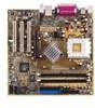
1 Onboard LED. This onboard LED lights up if there is a standby power on the motherboard. This LED acts as a reminder to turn off the system power before plugging or unplugging devices. 2 ATX power connector. This standard 20-pin connector connects to an ATX 12V power supply. The power supply must have at least 1A on the +5V standby lead (+5VSB). 3 CPU socket. This is a Zero Insertion Force (ZIF) socket for AMD Athlon XP™ processors. 4 Northbridge controller. The NVIDIA® nForce2™ IGP Northbridge controller chip supports a 64/128-bit DDR memory controller and up to 2GB of 333/266/200MHz DDR memory . The Northbridge controller is equipped with a maximum 128 MB integrated graphics UMA share memory for the onboard VGA. 5 DDR DIMM sockets. Two Double Data Rate Dual Inline Memory Module (DDR DIMM) sockets are available for up to 2 GB of DDR SDRAM. This memory technology supplies data transfer rates up to 5.4 GB/s for 333MHz DDR SDRAM. 6 IDE connectors. These dual-channel bus master IDE connectors support up to four UltraDMA133, PIO Modes 0-4 IDE devices. Both the primary (blue) and secondary (black) connectors are slotted to prevent incorrect insertion of the IDE cable. 7 Floppy disk connector. This connector is for the provided FDD cable for the floppy disk drive. One side of the connector is slotted to prevent incorrect insertion of the FDD cable. 8 Flash ROM. This 4 Mb LPC chip contains the programmable BIOS program. 9 Super I/O chipset. ITE IT8712F-A offers support for a variety of I/O functions. Provides two high-speed UART compatible serial ports, and a parallel port with EPP and ECP capabilities. The Super I/O controller supports a floppy disk drive, PS/2 keyboard, and PS/2 mouse. 10 Southbridge controller. This motherboard comes with the brand new NVIDIA® nForce2™ MCP integrated peripheral Southbridge controller. This controller communicates at 800 MB/s with the Northbridge chip for maximum bandwith required to support PCI, USB, and Fast Ethernet devices. The controller also supports standard UltraDMA133 and has separate data paths for each IDE channel. 11 AGP slot. The Accelerated Graphics Port (AGP) slot supports 1.5 V AGP 8X/4X mode graphics cards for 3D graphics applications. The AGP slot also supports digital visual interface (DVI) cards for digital display on LCD monitors and projectors. ASUS A7N8X-VM/400 motherboard user guide 1-5
-
 1
1 -
2
-
3
-
4
-
5
-
6
-
7
-
8
-
9
-
 10
10 -
 11
11 -
 12
12 -
 13
13 -
 14
14 -
 15
15 -
 16
16 -
 17
17 -
 18
18 -
 19
19 -
 20
20 -
21
-
22
-
23
-
24
-
25
-
26
-
27
-
28
-
29
-
30
-
31
-
32
-
33
-
34
-
35
-
36
-
37
-
38
-
39
-
40
-
41
-
42
-
43
-
44
-
45
-
46
-
47
-
48
-
49
-
50
-
51
-
52
-
53
-
54
-
55
-
56
-
57
-
58
-
59
-
60
-
61
-
62
-
63
-
64
 |
 |
