Asus AP1720-E2 AP1720-E2 English version manual
Asus AP1720-E2 Manual
 |
View all Asus AP1720-E2 manuals
Add to My Manuals
Save this manual to your list of manuals |
Asus AP1720-E2 manual content summary:
- Asus AP1720-E2 | AP1720-E2 English version manual - Page 1
AP1720-E2 Dual Intel® Xeon™ 5U Rackmount Server 800/533MHz Front Side Bus User Guide - Asus AP1720-E2 | AP1720-E2 English version manual - Page 2
. All Rights Reserved. No part of this manual, including the products and software described in it, may be ASUS. ASUS assumes no responsibility or liability for any errors or inaccuracies that may appear in this manual, including the products and software described in it. Product warranty or service - Asus AP1720-E2 | AP1720-E2 English version manual - Page 3
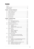
Safety information vi About this guide vii Chapter 1: Product introduction Motherboard information 2-4 2.3 Central Processing Unit (CPU 2-5 2.3.1 Overview 2-5 2.3.2 Installing the CPU 2-5 2.3.3 Installing the CPU heatsink and fan 2-7 2.4 System memory 2-10 2.4.1 Overview 2-10 2.4.2 Memory - Asus AP1720-E2 | AP1720-E2 English version manual - Page 4
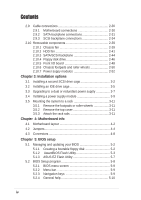
info 4.1 Motherboard layout 4-2 4.2 Jumpers 4-4 4.3 Connectors 4-8 Chapter 5: BIOS setup 5.1 Managing and updating your BIOS 5-2 5.1.1 Creating a bootable floppy disk 5-2 5.1.2 AwardBIOS Flash Utility 5-3 5.1.3 ASUS EZ Flash Utility 5-7 5.2 BIOS Setup program 5-8 5.2.1 BIOS menu screen - Asus AP1720-E2 | AP1720-E2 English version manual - Page 5
15 5.3.5 Third IDE Master 5-16 5.3.6 Fourth IDE Master 5-16 5.4 Advanced menu 5-17 5.4.1 Advanced BIOS Features 5-17 5.4.2 CPU Configuration 5-18 5.4.3 Memory Configuration 5-19 5.4.4 Chipset 5-20 5.4.5 Onboard Device 5-23 5.4.6 PCIPnP 5-28 5.4.7 USB Configuration 5-30 5.5 Power menu 5-31 - Asus AP1720-E2 | AP1720-E2 English version manual - Page 6
to comply with the limits for a Class B digital device, pursuant to Part 15 of the FCC Rules. These limits are designed to provide reasonable and, if not installed and used in accordance with manufacturer's instructions, may cause harmful interference to radio communications. However, there is - Asus AP1720-E2 | AP1720-E2 English version manual - Page 7
by yourself. Contact a qualified service technician or your dealer. Operation Safety • Any mechanical operation on this server must be conducted by certified or experienced engineers. • Before operating the server, carefully read all the manuals included with the server package. • Before using the - Asus AP1720-E2 | AP1720-E2 English version manual - Page 8
server. Contents This guide contains the following parts: 1. Chapter 1: Product Introduction This chapter describes the general features of the AP130-E1 server with the barebone server. This section also provides a troubleshooting guide for solving common problems when using the barebone server. viii - Asus AP1720-E2 | AP1720-E2 English version manual - Page 9
properly, take note of the following symbols used throughout this manual. WARNING: Information to prevent injury to yourself when trying to Reference Visit the ASUS websites worldwide that provide updated information for all ASUS hardware and software products. Refer to the ASUS contact information - Asus AP1720-E2 | AP1720-E2 English version manual - Page 10
x - Asus AP1720-E2 | AP1720-E2 English version manual - Page 11
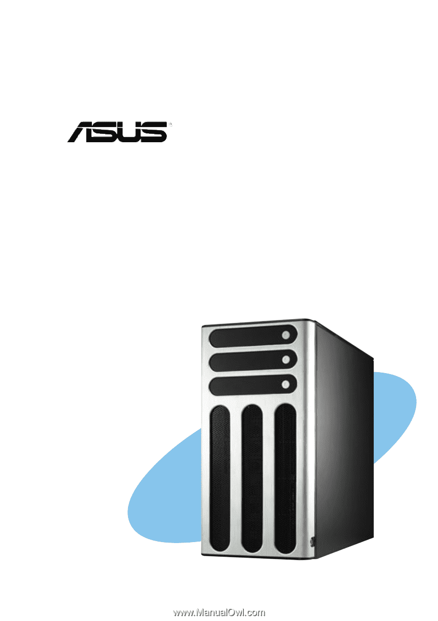
Product introduction Chapter 1 This chapter describes the general features of the barebone server. It includes sections on the front panel and rear panel specifications. ASUS AP1720-E2 user guide 1-1 - Asus AP1720-E2 | AP1720-E2 English version manual - Page 12
Configurations AS8 AS4 AA4 AI4 ASUS AK25 5U rackmount chassis with: • ASUS NCCH-DL motherboard • 600 AP1720-E2 support CD with ASWM** • TrendMicro® ServerProtect® CD Documentation • ASUS AP1720-E2 user guide • ASUS NCCH-DL user guide Optional items • ASUS AK25 rackmount rail kit • ASUS - Asus AP1720-E2 | AP1720-E2 English version manual - Page 13
1.2 System specifications The ASUS AP1720-E2 is a barebone server system featuring the ASUS NCCH-DL motherboard. The server supports dual Intel® Xeon™ processors in 604-pin sockets, and includes the latest technologies through the chipsets embedded on the motherboard. Chassis Pedestal or - Asus AP1720-E2 | AP1720-E2 English version manual - Page 14
1.3 Front panel features The AP1720-E2 chassis displays a stylish front bezel with lock. The bezel covers the system components on the front panel and serves as security. Open the bezel to - Asus AP1720-E2 | AP1720-E2 English version manual - Page 15
If you wish to access front I/O ports and floppy disk drive without opening the bezel, hold the tab and move the sliding panel (rightmost panel) to the left as shown. ASUS AP1720-E2 barebone server 1-5 - Asus AP1720-E2 | AP1720-E2 English version manual - Page 16
panel features The rear panel includes a slot for the motherboard rear I/O ports, expansion slots, a chassis lock and intrusion Parallel port USB ports Microphone port Line Out port SCSI connectors* * On AS8/AS4 configuration only. Power connector 12 cm system fan Chassis cover lock IEEE 1394 port - Asus AP1720-E2 | AP1720-E2 English version manual - Page 17
) 2 1 3 5 4 10 7 6 9 1. Power supply cage 2. CD-ROM drive 3. 2 x 5.25-inch drive bays 4. Hard disk drive cage 5. Chassis fan 8 6. Expansion card locks 7. NCCH-DL motherboard 8. Chassis roller wheels 9. Front I/O board 10. Chassis intrusion switch ASUS AP1720-E2 barebone server 1-7 - Asus AP1720-E2 | AP1720-E2 English version manual - Page 18
AA4 (four hot-swap SATA configuration) 2 1 3 5 10 6 12 11 4 7 9 8 AS4 (four hot-swap SCSI configuration) 13 11 14 1-8 Chapter 1: Product introduction - Asus AP1720-E2 | AP1720-E2 English version manual - Page 19
motherboard 8. Chassis roller wheels 9. Front I/O board 10. Chassis intrusion switch 11. HDD fan 12. SATA backplane (hidden) 13. SCSI backplane (hidden) 14. ASUS U160/U320 SCSI card 15. Second SCSI backplane (hidden) 16. Second HDD fan 17. Second hard disk drive cage ASUS AP1720-E2 barebone server - Asus AP1720-E2 | AP1720-E2 English version manual - Page 20
LED information The barebone system comes with Red and Green HDD rebuilding using the RAID card blinking alternately* SAF-TE** function Blinking Read/write data into the HDD * For SCSI models only (AS8/AS4) ** SCSI Access Fault-Tolerant Enclosure (on AS8/AS4 models only) • The Power, HDD Access, - Asus AP1720-E2 | AP1720-E2 English version manual - Page 21
Chapter 2 This chapter lists the hardware setup procedures that you have to perform when installing or removing system components. Hardware setup ASUS AP1720-E2 barebone server 2-1 - Asus AP1720-E2 | AP1720-E2 English version manual - Page 22
2.1 Chassis cover The chassis features a "screwless design" that allows convenient assembly and disassembly. You can simply push or slide mechanical bolts and locks to remove the cover. 2.1.1 Removing the side cover 1. Push up the chassis lock on the rear panel to release the side cover. 1 2. Slide - Asus AP1720-E2 | AP1720-E2 English version manual - Page 23
fit the designated holes. 2. Slide the cover toward the front until it snaps in place. 3. Push down the chassis lock to secure the side cover. 1 2 3 3 ASUS AP1720-E2 barebone server 2-3 - Asus AP1720-E2 | AP1720-E2 English version manual - Page 24
information The barebone server comes with the ASUS NCCH-DL motherboard already installed. The motherboard is secured to the chassis by ten (10) screws as indicated by circles in the illustration below. Refer to "Chapter 4 Motherboard information" for detailed information on the motherboard. This - Asus AP1720-E2 | AP1720-E2 English version manual - Page 25
CPU Note in the above illustration that the CPU has a gold triangular mark on one corner. This mark indicates the processor Pin 1 that should match a specific corner of the CPU socket. If installing only one CPU, use the socket CPU1. Socket for CPU1 Socket for CPU2 ASUS AP1720-E2 barebone server - Asus AP1720-E2 | AP1720-E2 English version manual - Page 26
the socket may bend the pins and severely damage the CPU! Follow these steps to install a CPU. 1. Locate the 604-pin ZIF sockets on the motherboard. Flip up the socket lever and push it all the way to the other side. Make sure that the socket lever is pushed back all - Asus AP1720-E2 | AP1720-E2 English version manual - Page 27
depending on the pin definition of your CPU fan cables. Refer to the motherboard user guide for information. • Remove the chassis fan to have more space for the CPU fan and heatsink assembly installation. Refer to section "2.10 Removable components" for details. ASUS AP1720-E2 barebone server 2-7 - Asus AP1720-E2 | AP1720-E2 English version manual - Page 28
screw holes on the CEK spring. The CEK springs come pre-installed under the CPU sockets to support the weight of the CPU heatsinks. It is recommended that you keep the springs installed to prevent motherboard breakage. 2. Use a Phillips screwdriver to tighten the four heatsink screws in a diagonal - Asus AP1720-E2 | AP1720-E2 English version manual - Page 29
4. Repeat steps 1 to 3 to install the other heatsink if you have installed a second CPU, then connect the fan cable to the 4-pin connector labeled CPU_FAN2. The heatsinks appear as shown when installed. CPU2 fan connector (CPU_FAN2) ASUS AP1720-E2 barebone server 2-9 - Asus AP1720-E2 | AP1720-E2 English version manual - Page 30
Always install DIMMs with the same CAS latency. For optimum compatibility, it is recommended that you obtain memory modules from the same vendor. 4. Make sure that the memory frequency matches the CPU FSB (Front Side Bus). Refer to Table 2. 5. DIMMs installed into any three sockets will function in - Asus AP1720-E2 | AP1720-E2 English version manual - Page 31
synchronization CPU FSB 800 MHz 533 MHz 400 MHz DDR DIMM Type PC3200 PC2700 PC2100 Memory Frequency 400 MHz 333 MHz 266 MHz Obtain DDR DIMMs only from ASUS qualified vendors for better system performance. Visit the ASUS website (www.asus.com) for the latest QVL. ASUS AP1720-E2 barebone server - Asus AP1720-E2 | AP1720-E2 English version manual - Page 32
do so may cause damage to both the motherboard and the components. Follow these steps to install fan. Refer to section "2.10 Removable components" for instructions. 1. Unlock a DIMM socket by pressing the retaining steps to remove a DIMM. 1. While supporting the DIMM with your fingers, press the - Asus AP1720-E2 | AP1720-E2 English version manual - Page 33
front edge of the chassis outward to release the front panel assembly. Lock lever 2. Pull and swing the left edge of the front panel outward. ASUS AP1720-E2 barebone server 2-13 - Asus AP1720-E2 | AP1720-E2 English version manual - Page 34
3. Unhook the hinge-like tabs from the holes on the right side of the front panel to completely detach the front panel assembly from the chassis. Do not use too much force when removing the front panel assembly. Hinge-like tab 2-14 Chapter 2: Hardware setup - Asus AP1720-E2 | AP1720-E2 English version manual - Page 35
and fit the four (4) hooked tabs to the left side of the chassis until the tabs snap back in place. 1 Hinge-like tab 2 Hooked tab ASUS AP1720-E2 barebone server 2-15 - Asus AP1720-E2 | AP1720-E2 English version manual - Page 36
cable before installing or removing any system components. Failure to do so may cause damage to the motherboard and other system components! Three 5.25-inch drive bays are located on the upper front part of the chassis. A CD-ROM drive that comes standard with the system package 1 occupies the - Asus AP1720-E2 | AP1720-E2 English version manual - Page 37
on the back of the drive. 6. Connect a 4-pin plug from the power supply to the power connector on the back of the drive. IDE cable ASUS AP1720-E2 barebone server Power plug 2-17 - Asus AP1720-E2 | AP1720-E2 English version manual - Page 38
each side of the bay cover. 10. Re-install the front panel assembly when done. Refer to section "2.5.2 Re-installing the front panel assembly" for instructions. 2-18 Chapter 2: Hardware setup - Asus AP1720-E2 | AP1720-E2 English version manual - Page 39
disk drive If you purchased an AS8, AS4, or AA4 configured model, follow these instructions to install a hot-swap SATA or SCSI support. Use a Phillips (cross) screwdriver to remove the bracket when you are ready to install a hard disk in the drive tray. Metal bracket ASUS AP1720-E2 barebone server - Asus AP1720-E2 | AP1720-E2 English version manual - Page 40
5. Place a SATA or an SCA SCSI hard disk to the drive tray, and secure it with four screws. 6. Carefully insert drive tray and push it all the way to the depth of the bay until just a small fraction of the tray edge protrudes. 7. Push the tray lever until it clicks, and secures the drive tray in - Asus AP1720-E2 | AP1720-E2 English version manual - Page 41
front panel assembly. Refer to section 2.5.1 for instructions. 2. Use a Phillips (cross) screwdriver to attach Rail 1 to the side of the drive as shown. The rail end should be on the side of the drive connectors. Rail handle Drive connectors Hole 1 Hole 3 ASUS AP1720-E2 barebone server 2-21 - Asus AP1720-E2 | AP1720-E2 English version manual - Page 42
3. Attach Rail 2 to the other side of the drive as shown. The rail end should be on the side of the drive connectors. Rail handle Hole 1 Hole 3 4. Check the HDD jumper setting. Refer to the label pasted on the HDD for the description of jumper settings. The setting "Cable Select" is recommended. - Asus AP1720-E2 | AP1720-E2 English version manual - Page 43
a Serial ATA hard disk drive to the first hard disk drive cage: 1. Follow instructions 1 to 6 of the previous section. 2. Connect the 15-pin SATA power plug to the motherboard. Refer to the motherboard user guide for the location of the SATA connectors. ASUS AP1720-E2 barebone server 2-23 - Asus AP1720-E2 | AP1720-E2 English version manual - Page 44
an IDE or Serial ATA hard disk drive to the optional internal hard disk drive cage (non-swap). 1. Install the internal HDD cage following the instructions on Chapter 3 "Installation options". 2. Follow steps 1 of 4 of the section "Installing an IDE hard disk drive to the first hard disk drive cage - Asus AP1720-E2 | AP1720-E2 English version manual - Page 45
dummy cover into the slot opening until the hook tab clicks in place. Hook tab Flat end 3. When installed, the dummy cover appears as shown. ASUS AP1720-E2 barebone server 2-25 - Asus AP1720-E2 | AP1720-E2 English version manual - Page 46
2.8 Expansion cards The chassis is designed with a screwless expansion slot frame on the rear panel. This design feature allows you to install or remove an expansion card in less steps. Make sure to unplug the power cord before installing or removing expansion cards. Failure to do so may cause - Asus AP1720-E2 | AP1720-E2 English version manual - Page 47
3. When the card is in place, secure it with the plastic card lock that you removed earlier. Card lock tab ASUS AP1720-E2 barebone server 2-27 - Asus AP1720-E2 | AP1720-E2 English version manual - Page 48
as some types of RAID cards, you need guides that keep the expansion cards firmly seated on the slots. 1. The internal drive cage is optional and separately purchased. See section "Chapter 3: Installation options" for instructions on installing the drive cage. 2. The AS4, AA4, and AI4 models support - Asus AP1720-E2 | AP1720-E2 English version manual - Page 49
2.8.3 Removing an expansion card To remove an expansion card: 1. Remove the plastic card lock that secures the expansion card. Card lock tab 2. Firmly hold the expansion card and pull it out of the slot. 3. Place the plastic card lock back where you removed it. ASUS AP1720-E2 barebone server 2-29 - Asus AP1720-E2 | AP1720-E2 English version manual - Page 50
6. Chassis intrusion 7. Front panel cable 8. Front panel audio 9. Chassis fan cable 10. SMBus cable to backplane 11. Front panel IEEE 1394 port Refer to the motherboard user guide for detailed information on the connectors. 2-30 Chapter 2: Hardware setup - Asus AP1720-E2 | AP1720-E2 English version manual - Page 51
) A SATA backplane comes pre-installed in the AP1720-E2 AA4 model. The SATA backplane has four 15-pin SATA connectors to support Serial ATA hard disk drives. The backplane design incorporates connector CON1 CON3 CON5 CON7 Back side connector CON2 CON4 CON6 CON8 ASUS AP1720-E2 barebone server 2-31 - Asus AP1720-E2 | AP1720-E2 English version manual - Page 52
This side includes the power connectors, SATA interfaces for the SATA RAID card, and SMBus connectors. Fan connector (for HDD fan) Power CON2 CON4 CON6 CON8 The back side SATA connectors are attached to the motherboard SATA connectors via the supplied SATA cables. Refer to the illustration on - Asus AP1720-E2 | AP1720-E2 English version manual - Page 53
# for each SATA HDD bay. J1 setting (1-3 shorted, 2-4 shorted) Device Drive Bay 1 SATA BP ID CON2 Drive Bay 2 CON4 Drive Bay 3 CON6 Drive Bay 4 CON8 ASUS AP1720-E2 barebone server 2-33 - Asus AP1720-E2 | AP1720-E2 English version manual - Page 54
models only) Two SCSI backplanes come pre-installed in the AP1720-E2 AS8 model. One SCSI backplane comes pre-installed in the AS4 model. The SCSI backplane has four 68-pin SCSI connectors to support SCA SCSI hard disks. The backplane design incorporates a hot swap feature to allow easy connection - Asus AP1720-E2 | AP1720-E2 English version manual - Page 55
) (connects the SMB cable from the motherboard) SMBus connector (lower 6-1 pins) (connects the SMB cable to the second backplane) 68-pin SCSI connector (connects the SCSI cable from the SCSI/RAID card) 68-pin SCSI connector (with SCSI multi-mode terminator) ASUS AP1720-E2 barebone server 2-35 - Asus AP1720-E2 | AP1720-E2 English version manual - Page 56
(connect power plugs from the power supply) Fan connector (for HDD fan) SMBus connector (upper 6-1 pins) (connects the SMB cable from the motherboard) SMBus connector (lower 6-1 pins) (connects the SMB cable to the second backplane) 68-pin SCSI connector (connects the SCSI cable from the SCSI - Asus AP1720-E2 | AP1720-E2 English version manual - Page 57
(BPB2) J1 setting (3-5 shorted, 4-6 shorted) Device SCSI ID# Drive Bay 5 ID4 Drive Bay 6 ID5 Drive Bay 7 ID6 Drive Bay 8 ID8 GEM 318 SAF-TE ID11 ASUS AP1720-E2 barebone server 2-37 - Asus AP1720-E2 | AP1720-E2 English version manual - Page 58
Non-Cascade configuration First backplane (BPB1) J1 setting (1-3 shorted, 2-4 shorted) Device SCSI ID# Drive Bay 1 ID0 Drive Bay 2 ID1 Drive Bay 3 ID2 Drive Bay 4 ID3 GEM 318 SAF-TE ID15 (SCSI channel-0) Second backplane (BPB2) J1 setting (1-3 shorted, 2-4 shorted) Device SCSI ID# - Asus AP1720-E2 | AP1720-E2 English version manual - Page 59
the connector SYSTEM_FAN on the motherboard. 2. Press the tabs on the outer corners of the system fan, then pull the fan out of the chassis. 3. Lift the chassis fan case lock hooks, then push the fan from the center of the case until it is detached. Lock hooks ASUS AP1720-E2 barebone server 2-39 - Asus AP1720-E2 | AP1720-E2 English version manual - Page 60
4. Pull the fan out from the fan case, then set aside. To re-install the chassis fan: 1. Insert the new fan to the chassis fan cage. 2. Firmly hold the chassis fan on the side with the tabs and position it into its slot, making sure that the four hooks underneath the fan match the corresponding - Asus AP1720-E2 | AP1720-E2 English version manual - Page 61
the rear panel. 4. Re-connect the 3-pin fan cable from the connector SYSTEM_FAN on the motherboard. 2.10.2 HDD fan To remove the HDD fan: 1. Loosen the thumb screw that secures the push it inward (toward the motherboard) before pulling it out of the chassis. ASUS AP1720-E2 barebone server 2-41 - Asus AP1720-E2 | AP1720-E2 English version manual - Page 62
4. Locate four hooks inside the HDD fan case. 5. Press the fan case hooks outwards until the fan detaches from the case. 6. Slightly press the center of the fan vent to flush the fan out from the case. Set the HDD fan aside. To re-install the HDD fan: 1. Insert a new HDD fan to the fan case until it - Asus AP1720-E2 | AP1720-E2 English version manual - Page 63
fit it to the drive cage. You hear a click when the fan cage correctly fits in place. 5. Secure the fan cage with the thumb screw. ASUS AP1720-E2 barebone server 2-43 - Asus AP1720-E2 | AP1720-E2 English version manual - Page 64
2.10.3 SATA/SCSI backplane To remove the SATA/SCSI backplane: 1. Remove the HDD fan cage. Refer to section "2.10.2 HDD fans" for instructions. 2. Disconnect all cables from the SATA/SCSI backplane. When disconnecting a cable, hold and firmly pull the cable plug. DO NOT pull the cable itself. Doing - Asus AP1720-E2 | AP1720-E2 English version manual - Page 65
the drive cage. 4. Connect the appropriate cables to the backplane. Refer to sections "2.9.2 SATA backplane connections" and "2.9.3 SCSI backplane connections" for details. Rail-like dents ASUS AP1720-E2 barebone server 2-45 - Asus AP1720-E2 | AP1720-E2 English version manual - Page 66
You need to remove the front panel assembly before you can remove the floppy disk drive. Refer to section "2.5.1 Removing the front panel assembly" for instructions. To remove the floppy disk drive: 1. Remove the screw that secures the drive to the chassis. 2. Carefully pull out the drive from the - Asus AP1720-E2 | AP1720-E2 English version manual - Page 67
cable 3. Carefully push the drive into the bay until the drive cage fits the front edge of the bay. 4. Secure the drive cage with a screw. ASUS AP1720-E2 barebone server 2-47 - Asus AP1720-E2 | AP1720-E2 English version manual - Page 68
need to remove the front panel assembly before you can remove the front I/O board. Refer to section "2.5.1 Removing the front panel assembly" for instructions. To remove the front I/O board: 1. Remove the screw that secures the front I/O board bracket to the front panel. 2. Carefully pull out the - Asus AP1720-E2 | AP1720-E2 English version manual - Page 69
until the bracket fits the front edge of the bay. 4. Secure the I/O board bracket with a screw. IEEE 1394 Front panel cable plug audio cable plug ASUS AP1720-E2 barebone server 2-49 - Asus AP1720-E2 | AP1720-E2 English version manual - Page 70
10.6 Chassis footpads and roller wheels The barebone server system is shipped with four footpads attached to a rack (Refer to "Chapter 3 Installation options" of this user guide, and to the "Rackmount Kit" user guide for instructions) To remove the footpads: 1. Lay the system chassis on its side. - Asus AP1720-E2 | AP1720-E2 English version manual - Page 71
a Phillips screwdriver to remove the screws that secure the wheels to the bottom of the chassis. 3. Repeat step 2 to remove the other three roller wheels. ASUS AP1720-E2 barebone server 2-51 - Asus AP1720-E2 | AP1720-E2 English version manual - Page 72
2.10.7 Power suppy modules The barebone server system power supply modules come in three configurations: 600 W single power supply ( installing power supply modules to the barebone system. You MUST disconnect all power cable plugs from the motherboard and other installed devices before removing - Asus AP1720-E2 | AP1720-E2 English version manual - Page 73
hand to push the power supply module from inside the power supply cage, then carefully pull out the module from the chassis. Metal plate bar ASUS AP1720-E2 barebone server 2-53 - Asus AP1720-E2 | AP1720-E2 English version manual - Page 74
To install a 600 W single power supply module: 1. Firmly hold the power supply module and insert it into the power supply cage. 2. Push the power supply all the way in until its outer end aligns with the rear panel. Be careful with the power supply cables when inserting the power supply module into - Asus AP1720-E2 | AP1720-E2 English version manual - Page 75
module into the cage. Due to space constraints, the cables may get entangled with the installed components or other cables, causing the cables to break! ASUS AP1720-E2 barebone server 2-55 - Asus AP1720-E2 | AP1720-E2 English version manual - Page 76
until it fits in place. 3. Secure the power supply to the chassis with two screws on the metal brackets on each side. The standard server system comes with two power supply modules with no redundant power function. To achieve redundant power supply function, you must install an optional third power - Asus AP1720-E2 | AP1720-E2 English version manual - Page 77
Chapter 3 This chapter describes how to install optional components into the barebone server. Installation options ASUS AP1720-E2 barebone server 3-1 - Asus AP1720-E2 | AP1720-E2 English version manual - Page 78
described in this chapter are not included in the standard barebone system package. These items are purchased separately. 3.1 Installing you wish to upgrade your 4-SCSI configuration system (AS4 model) to an 8-SCSI configuration (AS8). AS4 AS8 Clear the space under the first SCSI drive - Asus AP1720-E2 | AP1720-E2 English version manual - Page 79
the support bracket for the drive trays to the left side of the cage with the three protruding tabs matching the elongated holes on the chassis. Front screw holes Protruding tabs Screw holes SCSI drive tray support bracket Elongated holes for bracket ASUS AP1720-E2 barebone server 3-3 - Asus AP1720-E2 | AP1720-E2 English version manual - Page 80
6. Insert the tabs into the holes. You may need to swing the bracket a bit from left to right and back to fully insert the tabs. 7. When the tabs are fully inserted in the holes, swing the bracket to the right until one side is flat to the chassis. 8. Secure the bracket with two screws in the holes - Asus AP1720-E2 | AP1720-E2 English version manual - Page 81
drive cage Perform this installation if you wish to upgrade your 4-SCSI configuration system (AS4 model) to a combination 4-SCSI/4-IDE configuration. 4-SCSI configuration 4-SCSI/4-IDE configuration Clear the front panel until it fits in place. Screw hole ASUS AP1720-E2 barebone server 3-5 - Asus AP1720-E2 | AP1720-E2 English version manual - Page 82
3. Make sure that the drive cage is fits snugly to the bay as shown. The drive cage is properly installed when it is parallel to the front panel, and the screw hole matches the hole of the first drive cage. 4. Secure the drive cage with a screw. Screw hole 3-6 Chapter 3: Installation options - Asus AP1720-E2 | AP1720-E2 English version manual - Page 83
wish to upgrade your barebone server system from 600 W single power supply to 600 W dual or redundant power supply. 1. Remove the single power supply following the instructions in the section "2.10 Insert the power supply cables and plugs to the power supply cage. ASUS AP1720-E2 barebone server 3-7 - Asus AP1720-E2 | AP1720-E2 English version manual - Page 84
5. Push the power supply halfway to the power supply cage, then attached the a metal bracket on each side of the power supply with two screws. 6. Push the power supply to the power supply cage until the metal brackets and the chassis screw holes align. 7. Secure the power supply to the chassis with - Asus AP1720-E2 | AP1720-E2 English version manual - Page 85
3.4 Installing a power supply module Perform this installation if you wish to upgrade your barebone server system from 600 W dual to 600 W redundant power supply. 1. Press down the rubber the power supply module to the empty bay with the power connector on top. ASUS AP1720-E2 barebone server 3-9 - Asus AP1720-E2 | AP1720-E2 English version manual - Page 86
4. Push the power supply module inside the bay until it is aligned with the other power supply modules. The pictures shows the power supply module when installed. 3-10 Chapter 3: Installation options - Asus AP1720-E2 | AP1720-E2 English version manual - Page 87
Refer to the Rackmount Rail Kit installation guide for instructions on how to attach the rails and on the barebone server system and the corresponding rails on the industrial rack. The AK25 Rackmount Rail Kit is an optional item and is purchased separately. ASUS AP1720-E2 barebone server 3-11 - Asus AP1720-E2 | AP1720-E2 English version manual - Page 88
3-12 Chapter 3: Installation options - Asus AP1720-E2 | AP1720-E2 English version manual - Page 89
Chapter 4 This chapter includes the motherboard layout and brief descriptions of the jumpers and internal connectors. Motherboard info ASUS AP1720-E2 barebone server 3-1 - Asus AP1720-E2 | AP1720-E2 English version manual - Page 90
) DDR DIMM4 (72 bit, 184-pin module) 30.5cm (12in) 4.1 Motherboard layout PS/2KBMS T: Mouse B: Keyboard COM1 KBPWR1 CPU_FAN1 25cm (9.8in) ATX12V1 SPDIF_OUT1 REAR_FAN2 PCIX2 (64-bit, 66MHz 3V) ATXPWR1 Intel Hance Rapids (South Bridge) CLRTC1 CR2032 3V Lithium Cell CMOS Power PRI_IDE1 - Asus AP1720-E2 | AP1720-E2 English version manual - Page 91
power (3-pin KBPWR1) 4-4 2. RAID controller setting (3-pin RAID_EN1) 4-4 3. USB device wake-up (3-pin USBPW12, USBPW34) 4-5 4. CPU external frequency selection (3-pin J1) - Reset switch (2-pin RESET) 4-15 - System Management Interrupt (2-pin SMI) 4-15 ASUS AP1720-E2 barebone server 4-3 - Asus AP1720-E2 | AP1720-E2 English version manual - Page 92
) +5VSB NCCH-DL ® NCCH-DL Keyboard power setting 2. RAID controller setting (3-pin RAID_EN1) This jumper allows you enable or disable the Promise® PDC20319 RAID controller. NCCH-DL ® RAID_EN1 12 23 Enable (Default) NCCH-DL RAID controller setting Disable 4-4 Chapter 4: Motherboard info - Asus AP1720-E2 | AP1720-E2 English version manual - Page 93
bus clock). To ensure system stability, it is recommened that you keep the default setting. 246 J1 246 246 NCCH-DL ® 13 5 Auto-detect CPU FSB (Default) 13 5 100 MHz 246 13 5 133 MHz 246 13 5 166 MHz NCCH-DL CPU external frequency selection 13 5 200 MHz ASUS AP1720-E2 barebone server 4-5 - Asus AP1720-E2 | AP1720-E2 English version manual - Page 94
CMOS Except when clearing the RTC RAM, never remove the cap on CLRTC jumper default position. Removing the cap will cause system boot failure! 4-6 Chapter 4: Motherboard info - Asus AP1720-E2 | AP1720-E2 English version manual - Page 95
2 3 4-pin Fan (Force to 12V) NCCH-DL ® FM_CPU2 1 2 3 3-pin Fan (DC Mode) NCCH-DL USB CPU fan pin selection 1 2 3 4-pin Fan (Force to 12V) 7. IEEE 1394 setting (3-pin 1394_EN) These jumpers allow you to Enable (Default) Disable NCCH-DL 1394 Function setting ASUS AP1720-E2 barebone server 4-7 - Asus AP1720-E2 | AP1720-E2 English version manual - Page 96
pin FLOPPY1) This connector supports the provided floppy drive ribbon cable. After connecting one end to the motherboard, connect the other end to If you installed Serial ATA hard disks, you may create a RAID 0/RAID 1 configuration using the RAID feature of the Intel® 6300ESB ICH. Refer to page 5-26 - Asus AP1720-E2 | AP1720-E2 English version manual - Page 97
zigzag) on the IDE ribbon cable to pin 1. 4. GAME/MIDI connector (16-1 pin GAME1) This connector supports a GAME/MIDI module. Connect the GAME/MIDI cable to this connector. The GAME/MIDI port on the module GAME1 MIDI_IN J2B2 J2CY MIDI_OUT J2CX J2B1 +5V ASUS AP1720-E2 barebone server 4-9 - Asus AP1720-E2 | AP1720-E2 English version manual - Page 98
intrusion detection feature, remove the jumper cap from the pins. CHASSIS1 NCCH-DL ® +5VSB_MB Chassis Signal GND (Default) NCCH-DL Chassis intrusion connector 4-10 Chapter 4: Motherboard info - Asus AP1720-E2 | AP1720-E2 English version manual - Page 99
ATA RAID connectors (7-pin SATA_RAID1, SATA_RAID2) These Serial ATA connectors support SATA hard disks that you may configure as a RAID set. Through the onboard Promise® PDC20319 RAID controller SMBus connector NCCH-DL ® FAN_PWM I2C_4_CLK# GND I2C_4_DATA# +5VSB ASUS AP1720-E2 barebone server 4-11 - Asus AP1720-E2 | AP1720-E2 English version manual - Page 100
. NCCH-DL ® IDE_LED NCCH-DL IDE activity LED TIP: If the case-mounted LED does not light up, try reversing the 2-pin plug. 4-12 Chapter 4: Motherboard info - Asus AP1720-E2 | AP1720-E2 English version manual - Page 101
-DL ® Modem-Out Ground Ground Modem-In Right Audio Channel Ground Ground Left Audio Channel MODEM1 NCCH-DL Internal audio connectors AUX1 (White) CD1 (Black) ASUS AP1720-E2 barebone server 4-13 - Asus AP1720-E2 | AP1720-E2 English version manual - Page 102
(53.28W max.) at +12V. Connect the fan cables to the fan connectors on the motherboard, making sure that the black wire of each cable matches the ground pin of the connector. The CPU fan connectors support either a 3-pin or a 4-pin fan cable plug. Both connectors are slotted to ensure connection in - Asus AP1720-E2 | AP1720-E2 English version manual - Page 103
SMI) This lead connects to the chassis-mounted suspend switch. This feature allows you to manually put the system into suspend mode, or "green" mode, where system activity is instantly decreased to save power and to expand the life of certain system components. ASUS AP1720-E2 barebone server 4-15 - Asus AP1720-E2 | AP1720-E2 English version manual - Page 104
4-16 Chapter 4: Motherboard info - Asus AP1720-E2 | AP1720-E2 English version manual - Page 105
Chapter 5 This chapter tells how to change the system settings through the BIOS Setup menus. Detailed descriptions of the BIOS parameters are also provided. BIOS setup ASUS AP1720-E2 barebone server 3-1 - Asus AP1720-E2 | AP1720-E2 English version manual - Page 106
5.1 Managing and updating your BIOS • The original BIOS file for this motherboard is in the support CD. • Copy the original BIOS to a bootable floppy disk in case you need to restore the BIOS in the future. 5.1.1 Creating a bootable floppy disk 1. Do - Asus AP1720-E2 | AP1720-E2 English version manual - Page 107
BIOS Flash Utility screen appears. AwardBIOS Flash Utility for ASUS V1.06 (C) Phoenix Technologies Ltd. All Rights Reserved For Canterwood - NCCH-DL DATE: 06/01/2004 Flash Type - SST 49LF004A/B /3.3V File Name to Program : Message: Please input File Name! ASUS AP1720-E2 barebone server 5-3 - Asus AP1720-E2 | AP1720-E2 English version manual - Page 108
the current BIOS file. 8. The utility verifies the BIOS file in the floppy disk and starts flashing the BIOS file. AwardBIOS Flash Utility for ASUS V1.06 (C) Phoenix Technologies Ltd. All Rights Reserved For Canterwood - NCCH-DL DATE: 06/01/2004 Flash Type - SST 49LF004A/B /3.3V File Name to - Asus AP1720-E2 | AP1720-E2 English version manual - Page 109
following screen appears. AwardBIOS Flash Utility for ASUS V1.06 (C) Phoenix Technologies Ltd. All Rights Reserved For Canterwood - NCCH-DL DATE: 06/01/2004 Flash Type - SST 49LF004A/B /3.3V File Name to Program : 1001.bin Save current BIOS as : Message: ASUS AP1720-E2 barebone server 5-5 - Asus AP1720-E2 | AP1720-E2 English version manual - Page 110
Please Wait! 4. The utility saves the current BIOS file to the floppy disk, then returns to the BIOS flashing process. AwardBIOS Flash Utility for ASUS V1.06 (C) Phoenix Technologies Ltd. All Rights Reserved For Canterwood - NCCH-DL DATE: 06/01/2004 Flash Type - SST 49LF004A/B /3.3V File Name - Asus AP1720-E2 | AP1720-E2 English version manual - Page 111
Self Tests (POST). To update the BIOS using EZ Flash: 1. Visit the ASUS website (www.asus.com) to download the latest BIOS file for the motherboard and rename the same to NCCH-DL.ROM. 2. Save the BIOS file to updating the BIOS to prevent system boot failure! ASUS AP1720-E2 barebone server 5-7 - Asus AP1720-E2 | AP1720-E2 English version manual - Page 112
them in the CMOS RAM of the Flash ROM. The Flash ROM on the motherboard stores the Setup utility. When you start up the computer, the system provides and make your selections among the predetermined choices. Because the BIOS software is constantly being updated, the following BIOS setup screens and - Asus AP1720-E2 | AP1720-E2 English version manual - Page 113
:yy) Legacy Diskette A Floppy 3 Mode Support Primary IDE Master Primary IDE Slave Secondary IDE Master Secondary IDE Slave Third IDE Master Fourth IDE Master Base Memory Extended Memory Total Memory 11: 10 : 30 Wed, Jun 30 keys differ from one screen to another. ASUS AP1720-E2 barebone server 5-9 - Asus AP1720-E2 | AP1720-E2 English version manual - Page 114
5.2.4 General help On the right side of the menu screen is a brief description of the selected item. 5.2.5 Sub-menu An item with a sub-menu on any menu screen is distinguished by a solid triangle before the item. To display the sub-menu, select the item and press . 5.2.6 Scroll bar A scroll - Asus AP1720-E2 | AP1720-E2 English version manual - Page 115
88M, 3.5 in.] Floppy 3 Mode Support [Disabled] This is required to support older Japanese floppy drives. The Floppy 3 Mode feature allows reading and writing of 1.2MB (as opposed to 1.44MB) on a 3.5-inch floppy disk. Configuration options: [Disabled] [Enabled] ASUS AP1720-E2 barebone server 5-11 - Asus AP1720-E2 | AP1720-E2 English version manual - Page 116
Base/Extended/Total Memory [xxxK] The base memory, extended memory, and total memory values are None None Select Menu Item Specific Help Selects the type of fixed disk connected to the system. [Manual] lets you select the number of cylinders, heads, etc. Note: PRECOMP-65535 means NONE. Primary - Asus AP1720-E2 | AP1720-E2 English version manual - Page 117
set to [Auto]. • If you wish to manually configure the IDE drive items, set the Primary IDE Master to [Manual], and the Access Mode to [CHS]. PIO allows improved transfer speeds and data integrity for supported IDE drives. Configuration options: [Disabled] [Auto] ASUS AP1720-E2 barebone server 5-13 - Asus AP1720-E2 | AP1720-E2 English version manual - Page 118
correct configuration information supplied by the drive manufacturer. Incorrect settings may cause the system to fail to recognize the installed IDE drive! To manually enter the number of cylinder, head, precomp, landing zone, and sector per track for the drive, highlight an item, key-in the value - Asus AP1720-E2 | AP1720-E2 English version manual - Page 119
hard disk, if any, on the motherboard. Landing Zone Displays the drive's maximum Analysis, and Reporting Technology (S.M.A.R.T.) status if the IDE hard disk drive supports the feature. Otherwise, this item is grayed out and shows the the menu item descriptions. ASUS AP1720-E2 barebone server 5-15 - Asus AP1720-E2 | AP1720-E2 English version manual - Page 120
5.3.5 Third IDE Master When configuring a drive as Third IDE Master, refer to section "4.3.1 Primary IDE Master" for the menu item descriptions which are not discussed in this section. Third IDE Master Extended IDE Drive Access Mode Capacity Cylinder Head Precomp Landing Zone Sector Transfer Mode - Asus AP1720-E2 | AP1720-E2 English version manual - Page 121
field values may cause the system to malfunction! Advanced BIOS Features CPU Configuration Memory Configuration Chipset Onboard Device PCIPnP USB Configuration Select Menu Item Specific Help Item Specific Help Press [ENTER] to adjust Chipset Vcrore voltage. ASUS AP1720-E2 barebone server 5-17 - Asus AP1720-E2 | AP1720-E2 English version manual - Page 122
6V] [+1.7V] [+1.8V] DRAM Vcore Voltage [+2.6V] Allows adjustment of the DRAM Vcore voltage. Configuration options: [+2.8V] [+2.7V] [+2.6V] 5.4.2 CPU Configuration This menu shows the CPU configuration settings. Select an item then press to display a pop-up menu with the configuration options - Asus AP1720-E2 | AP1720-E2 English version manual - Page 123
CAS# Delay, and DRAM RAS# Precharge are configurable only when the Memory Timing Selectable item is set to [Manual]. CAS Latency Time [2] This item sets the latency (in clocks) of DRAM clocks used for DRAM parameters. Configuration options: [8] [7] [6] [5] ASUS AP1720-E2 barebone server 5-19 - Asus AP1720-E2 | AP1720-E2 English version manual - Page 124
[3] This item controls the idle clocks after issuing a precharge command to the DDR SDRAM. Configuration options: [4] [3] [2] Memory Parity Check [Enabled] Allows memory parity checking option ECC (Error-Correcting Code). Configuration options: [Disabled] [Enabled] 5.4.4 Chipset This menu shows the - Asus AP1720-E2 | AP1720-E2 English version manual - Page 125
Aperture Size [128] Select Menu Item Specific Help Size of the AGP Aperture. AGP Aperture Size [128] Allows you to select the size of mapped memory for AGP graphic data. Configuration options: [4] [8] [16] [32] [64] [128] [256] ASUS AP1720-E2 barebone server 5-21 - Asus AP1720-E2 | AP1720-E2 English version manual - Page 126
Configuration options: [Min=200] [Max=233] The minimum and maximum configuration values for the CPU Clock depend on the installed CPU. These values are detected by BIOS. CPU Clock Ratio [18 X] Sets the ratio between the CPU core clock and the Front Side Bus (FSB) frequency. Key-in a value within the - Asus AP1720-E2 | AP1720-E2 English version manual - Page 127
Enabled] [Disabled] [Enabled] [Enabled] [RAID] Select Menu Item Specific Help Enable/Disable Onboard CSA LAN device boot ROM support. Speech IC Reporter [Enabled] Allows you disable the onboard Gigabit LAN controller. Configuration options: [Disabled] [Enabled] ASUS AP1720-E2 barebone server 5-23 - Asus AP1720-E2 | AP1720-E2 English version manual - Page 128
controller operating mode. This item is configurable only when the Onboard Promise Controller item is set to [Enabled]. Configuration options: [IDE] [RAID] SuperIO Device SuperIO Device Serial Port1 Address Serial Port2 Address Onboard Parallel Port Parallel Port Mode EPP Mode Select ECP Mode Use - Asus AP1720-E2 | AP1720-E2 English version manual - Page 129
the MIDI port address. Configuration options: [Disabled] [201] [209] MIDI Port IRQ [10] Allows you to select the MIDI port IRQ. Configuration options: [Disabled] [5] [10] ASUS AP1720-E2 barebone server 5-25 - Asus AP1720-E2 | AP1720-E2 English version manual - Page 130
Mode]: PATA and SATA are combined. Max. of 2 IDE drives on each channel. [Enhanced Mode]: Enable both SATA and PATA. Max. of 6 IDE drives are supported. [SATA Only]: SATA is opeating in legacy mode. **On-Chip Serial ATA Setting The items SATA Mode, Serial ATA Port0 Mode, and Serial ATA Port1 - Asus AP1720-E2 | AP1720-E2 English version manual - Page 131
8 or 9 version operating system, as they do not support native mode. d. Setting to [SATA Only] allows you RAID], SATA operates in RAID mode. The RAID feature allows configuration of the installed IDE devices into a disk array. Configuration options: [IDE] [RAID ASUS AP1720-E2 barebone server 5-27 - Asus AP1720-E2 | AP1720-E2 English version manual - Page 132
devices. When set to [Manual], you can assign the available IRQ Resources to the PCI devices. Configuration options: [Auto] [Manual] When the item Resources not show colors properly. Setting this field to [Enabled] corrects this problem. If you are using a standard VGA card, leave this field - Asus AP1720-E2 | AP1720-E2 English version manual - Page 133
Resources sub-menu is activated when the Resources Controlled by parameter is set to [Manual]. Select [PCI Device] to assign an IRQ address to a Plug and Play device. Setting to [Reserved] reserves the IRQ address. Configuration options: [PCI Device] [Reserved] ASUS AP1720-E2 barebone server 5-29 - Asus AP1720-E2 | AP1720-E2 English version manual - Page 134
an item then press to display a pop-up menu with the configuration options. USB Configuration USB Controller USB 2.0 Support USB Legacy Mode Support [Enabled] [Enabled] [Enabled] Select Menu Item Specific Help Configures the USB controller. USB Controller [Enabled] Allows you enable or - Asus AP1720-E2 | AP1720-E2 English version manual - Page 135
[Enabled] [S1&S3] Select Menu Item Specific Help Enable/Disable ACPI support for Operating System. ACPI APIC Support [Enabled] Allows you to enable or disable the ACPI feature on the to use for system suspend. Configuration options: [S1(POS)] [S3(STR)] [S1&S3] ASUS AP1720-E2 barebone server 5-31 - Asus AP1720-E2 | AP1720-E2 English version manual - Page 136
5.5.1 APM Configuration This menu shows the Advanced Power Management (APM) configuration settings. Select an item then press to display a pop-up menu with the configuration options. APM Configuration Power Management HDD Power Down Suspend Mode Suspend Type Restore on AC Power Loss Video - Asus AP1720-E2 | AP1720-E2 English version manual - Page 137
Management System (DPMS) feature allows the BIOS to control the video display card if it supports the DPMS feature. [Blank Screen] only blanks the screen. Use this for monitors without Hot Key] [Mouse Left] [Mouse Right] [Any KEY] [BUTTON ONLY] [PS/2 Mouse] ASUS AP1720-E2 barebone server 5-33 - Asus AP1720-E2 | AP1720-E2 English version manual - Page 138
KB Power On Password [Enter] Allows you to set a password to turn the system power on. Highlight this item then press enter to set a password. To configure this item, you should set the Power On Function item to [Password]. Hot Key Power On [Ctrl-F1] Allows you to set a hot key combination to turn - Asus AP1720-E2 | AP1720-E2 English version manual - Page 139
Voltage VBAT Voltage +5VSB Voltage 1.45V 11.79V 3.26V 4.96V 3.10V 4.75V Select Menu Item Specific Help CPU VCORE Voltage, +12V Voltage, +3.3V Voltage, +5VCC Voltage, VBAT Voltage, +5VSB Voltage Auto-detected voltages through the onboard voltage regulators. ASUS AP1720-E2 barebone server 5-35 - Asus AP1720-E2 | AP1720-E2 English version manual - Page 140
Smart Q-Fan Configuration Smart Q-Fan Configuration Smart Fan Control System Target Temperature CPU1 Target Temperature CPU2 Target Temperature [Disabled] 50 60 60 Select Menu Item Specific Help Smart Fan Control [Disabled] Allows you to enable or disable the Smart Fan feature. Configuration - Asus AP1720-E2 | AP1720-E2 English version manual - Page 141
[CDROM] 3rd Boot Device [Hard Disk] These items allow you to select your boot device priority. Configuration options: [Removable] [Hard Disk] [CDROM] [Legacy LAN] [Disabled] ASUS AP1720-E2 barebone server 5-37 - Asus AP1720-E2 | AP1720-E2 English version manual - Page 142
5.6.2 Hard Disk Boot Priority Hard Disk Boot Priority 1. Bootable Add-in Cards Select Menu Item Specific Help Use or arrow to select a device, then press to move it up, or to move it down the list. Press to exit this menu. 5.6.3 Removable Device Priority Removable Device - Asus AP1720-E2 | AP1720-E2 English version manual - Page 143
[Enabled] When enabled, the BIOS will seek the floppy disk drive to determine whether the drive has 40 or 80 tracks. Configuration options: [Disabled] [Enabled] ASUS AP1720-E2 barebone server 5-39 - Asus AP1720-E2 | AP1720-E2 English version manual - Page 144
Show [Enabled] Allows you to enable or disable the ASUS Mylogo2™ feature. Configuration options: [Disabled] [Enabled] The ASUS MyLogo2 is automatically installed when you install ASUS Update from the support CD. You need to launch ASUS Update, then ASUS MyLogo2 to change the full screen logo. 5-40 - Asus AP1720-E2 | AP1720-E2 English version manual - Page 145
password field, and press twice. The following message appears: "PASSWORD DISABLED!!! Press any key to continue..." 2. Press any key to return to the menu. ASUS AP1720-E2 barebone server 5-41 - Asus AP1720-E2 | AP1720-E2 English version manual - Page 146
the password information is powered by the onboard button cell battery. If you need to erase the CMOS RAM, refer to section "2.6 Jumpers" for instructions. Password Check [Setup] This field requires you to enter the password before entering the BIOS setup or the system. Select [Setup] to require the - Asus AP1720-E2 | AP1720-E2 English version manual - Page 147
to discard your changes and exit • type [N], then press , or simply press , to cancel the command and return to the Exit menu ASUS AP1720-E2 barebone server 5-43 - Asus AP1720-E2 | AP1720-E2 English version manual - Page 148
Load Setup Defaults Select this option then press , or simply press , to load the optimized values for each of the Setup menu items. When a confirmation window appears (with a blinking [Y]): • press to load the default values • type [N], then press , or simply press , - Asus AP1720-E2 | AP1720-E2 English version manual - Page 149
Reference information Appendix This appendix gives information on the standard and redundant power supply that came with the barebone server. This section also provides a troubleshooting guide for solving common problems when using the barebone server. ASUS AP1720-E2 barebone server 3-1 - Asus AP1720-E2 | AP1720-E2 English version manual - Page 150
(no P3). Take note of the devices to which you should connect the plugs. P9 P10 P2 P1 P8 P5 P6 P7 P4 P11 P1 Motherboard 24-pin ATX power connector P2 Auxilliary 8-pin power connector P4 Floppy disk drive P5 ODD device (CD/DVD-ROM) P6 Peripheral device (optical drive - Asus AP1720-E2 | AP1720-E2 English version manual - Page 151
A.1.2 Specifications Input characteristics Input Voltage Normal Range Autorange Input Frequency Range 100 to 127 V ~ 10 A 200 to 240 V ~ 5 A 50 Hz to 60 Hz DC Output characteristics Output Voltage +3.33V +5V +12V -12V -5V +5VSB Max (A) 20 24 15 0.5 0.5 2.0 ASUS AP1720-E2 barebone server A-3 - Asus AP1720-E2 | AP1720-E2 English version manual - Page 152
which you should connect to the plugs. P15 P15 P15 P11 P4 P15 bb P15 aa P14 P15 aa Motherboard 24-pin ATX power connector bb Power SMBus connector P4 Motherboard 8-pin +12V AUX power connector P11 Floppy disk drive P14 Peripheral device (available) P15 Peripheral devices (available - Asus AP1720-E2 | AP1720-E2 English version manual - Page 153
mS 104º F to 122º F (40º C - 50º C) 20% - 90% non-condensing at 104º F (40º C) Sea level to 10,000 ft MTBF > 100,000 hours at 25º C ASUS AP1720-E2 barebone server A-5 - Asus AP1720-E2 | AP1720-E2 English version manual - Page 154
components. These problems only requires simple troubleshooting actions that you can perform by yourself. Problem Action The power LED on the server or on the it was turned on 1. Check the memory modules and make sure you installed the DIMMs the system supports. 2. Make sure that the DIMMs are - Asus AP1720-E2 | AP1720-E2 English version manual - Page 155
Problem Action The system continuously beeps after it was turned on 1. Check the memory modules and make sure you installed supported DIMMs. 2. Make sure that the DIMMs are properly Make sure that you have installed the LAN drivers from the support CD. ASUS AP1720-E2 barebone server A-7 - Asus AP1720-E2 | AP1720-E2 English version manual - Page 156
A-8 Appendix: Reference information
-
 1
1 -
 2
2 -
 3
3 -
 4
4 -
 5
5 -
 6
6 -
 7
7 -
8
-
9
-
10
-
11
-
12
-
13
-
14
-
15
-
16
-
17
-
18
-
19
-
20
-
21
-
22
-
23
-
24
-
25
-
26
-
27
-
28
-
29
-
30
-
31
-
32
-
33
-
34
-
35
-
36
-
37
-
38
-
39
-
40
-
41
-
42
-
43
-
44
-
45
-
46
-
47
-
48
-
49
-
50
-
51
-
52
-
53
-
54
-
55
-
56
-
57
-
58
-
59
-
60
-
61
-
62
-
63
-
64
-
65
-
66
-
67
-
68
-
69
-
70
-
71
-
72
-
73
-
74
-
75
-
76
-
77
-
78
-
79
-
80
-
81
-
82
-
83
-
84
-
85
-
86
-
87
-
88
-
89
-
90
-
91
-
92
-
93
-
94
-
95
-
96
-
97
-
98
-
99
-
100
-
101
-
102
-
103
-
104
-
105
-
106
-
107
-
108
-
109
-
110
-
111
-
112
-
113
-
114
-
115
-
116
-
117
-
118
-
119
-
120
-
121
-
122
-
123
-
124
-
125
-
126
-
127
-
128
-
129
-
130
-
131
-
132
-
133
-
134
-
135
-
136
-
137
-
138
-
139
-
140
-
141
-
142
-
143
-
144
-
145
-
146
-
147
-
148
-
149
-
150
-
151
-
152
-
153
-
154
-
155
-
156
 |
 |
Dual Intel
®
Xeon
™
5U Rackmount Server
800/533MHz Front Side Bus
AP1720-E2
User Guide