Asus AT4NM10-I User Manual
Asus AT4NM10-I Manual
 |
View all Asus AT4NM10-I manuals
Add to My Manuals
Save this manual to your list of manuals |
Asus AT4NM10-I manual content summary:
- Asus AT4NM10-I | User Manual - Page 1
AT4NM10-I Motherboard - Asus AT4NM10-I | User Manual - Page 2
ASUS"). Product warranty or service ASUS HAS BEEN ADVISED OF THE POSSIBILITY OF SUCH DAMAGES ARISING FROM ANY DEFECT OR ERROR IN THIS MANUAL OR PRODUCT. SPECIFICATIONS AND INFORMATION CONTAINED IN THIS MANUAL by downloading it from http://support.asus.com/download; encounter any problems in obtaining - Asus AT4NM10-I | User Manual - Page 3
Contents Notices...v Safety information vi About this guide vi AT4NM10-I specifications summary viii Chapter 1: Product introduction 1.1 Before you proceed 1-1 1.2 Motherboard overview 1-2 1.2.1 Motherboard layout 1-2 1.2.2 Layout contents 1-2 1.3 Central Processing Unit (CPU 1-3 1.4 System - Asus AT4NM10-I | User Manual - Page 4
2-10 2.5.3 ACPI APIC Support 2-10 2.5.4 Control EuP 2-11 2.5.5 APM Configuration 2-11 2.5.6 Hardware Monitor 2-11 2.6 Boot menu 2-12 2.6.1 Boot Device Priority 2-12 2.6.2 Boot Settings Configuration 2-12 2.6.3 Security 2-13 2.7 Tools menu 2-14 2.7.1 ASUS EZ Flash 2 2-14 2.7.2 Express - Asus AT4NM10-I | User Manual - Page 5
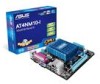
and used in accordance with manufacturer's instructions, may cause harmful interference to radio determined by turning the equipment off and on, the user is encouraged to try to correct the interference by at ASUS REACH website at http://green.asus.com/english/REACH.htm. DO NOT throw the motherboard - Asus AT4NM10-I | User Manual - Page 6
. • If you encounter technical problems with the product, contact a qualified service technician or your retailer. About this guide This user guide contains the information you need when installing and configuring the motherboard. How this guide is organized This guide contains the following parts - Asus AT4NM10-I | User Manual - Page 7
the following symbols used throughout this manual. DANGER/WARNING: Information to prevent injury to yourself when trying to complete a task. CAUTION: Information to prevent damage to the components when trying to complete a task. IMPORTANT: Instructions that you MUST follow to - Asus AT4NM10-I | User Manual - Page 8
AT4NM10-I specifications summary CPU Chipset Memory Graphics Expansion slot Storage Audio LAN USB ASUS special features Rear panel ports Integrated Intel® Atom™ D410 processor Intel® NM10 Single channel memory architecture - 2 x 240-pin DIMM sockets support maximum 4GB unbuffered non-ECC DDR2 - Asus AT4NM10-I | User Manual - Page 9
connector 8 Mb Flash ROM, AMI BIOS, PnP, DMI2.0, WfM2.0, SMBIOS 2.5 1 x Serial ATA cable 1 x I/O shield 1 x User Manual Drivers ASUS PC Probe II ASUS Update Anti-virus software (OEM version) Mini ITX form factor: 6.75 in x 6.75 in (17.1cm x 17.1cm) * Specifications are subject to change without - Asus AT4NM10-I | User Manual - Page 10
Chapter 1 Product introduction Thank you for buying an ASUS® AT4NM10-I motherboard! Before you start installing the motherboard, and hardware devices on it, check the items in your motherboard package. Refer to page ix for the list of accessories. If any of the items is damaged or missing, contact - Asus AT4NM10-I | User Manual - Page 11
) 1-13 6. Intel® Atom™ D410 processor 1-15 14. USB connectors (10-1 pin USB56, USB78) 1-13 7. DDR2 DIMM sockets 1-3 15. Digital audio connector (4-1 pin SPDIF_OUT) 1-17 8. System panel connector (10-1 pin F_PANEL) 1-16 16. Front panel audio connector (10-1 pin AAFP) 1-15 ASUS AT4NM10-I 1-2 - Asus AT4NM10-I | User Manual - Page 12
comes with an onboard Intel® Atom™ D410 processor and a specially designed CPU heatsink. D410 AT4NM10-I CPU - Atom D410 If you need to use an additional CPU fan, connect the CPU fan cable to the connector on the motherboard labeled CPU_FAN. AT4NM10-I AT4NM10-I CPU fan connector 1.4 System - Asus AT4NM10-I | User Manual - Page 13
This motherboard does not support DIMMs made up of 256 megabits (Mb) chips or less. AT4NM10-I Motherboard Qualified support A* B* • • • • - • - • - • 1.8V • 1.8V • - • - • - • - • - • - • - • - • - • - • - • - • - • (continued on the next page) ASUS AT4NM10 - Asus AT4NM10-I | User Manual - Page 14
-3SP0717A DS takeMS MS18T51280-3 DS UMAX DS UMAX U2S12D30YP-6E U2S24D30TP-6E Timing 4 4 5 Voltage - DIMM support A* B* • • • • • • 5 - • 5 - • 5 - • 5 - • - - • 5 - • DDR2-800 MHz capability Vendor A-Data A-Data A-Data A-Data Corsair Corsair Corsair Corsair Crucial Crucial - Asus AT4NM10-I | User Manual - Page 15
-HCF7 K4T2G084QA-HCF7 - DIMM Timing Voltage support A* B* 5 - •• 4 - •• 5 - •• 5 1.8V • • 4 - •• 5 - •• 5 - •• 4 - •• 5 - •• •• 5 - •• - - •• 6 - •• 6 - •• - - •• 6 - •• 6 - •• - - •• 4 1.8V • • (continued on the next page) ASUS AT4NM10-I 1-6 - Asus AT4NM10-I | User Manual - Page 16
H5PS1G83EFRS6C 852AK - - SS: Single-sided / DS: Double-sided DIMM support: • A*: Supports one module inserted into either slot. • B*: Supports one pair of modules inserted into both the slots. Visit the ASUS website at www.asus.com for the latest QVL. 1-7 Chapter 1: Product introduction - Asus AT4NM10-I | User Manual - Page 17
cover (if your motherboard is already installed in BIOS setup. 2. Assign an IRQ to the card. 3. Install the software drivers for the expansion card. 1.5.3 PCI slot The PCI slot supports cards such as a LAN card, SCSI card, USB card, and other cards that comply with PCI specifications. ASUS AT4NM10 - Asus AT4NM10-I | User Manual - Page 18
the RAM data in CMOS, which include system setup information such as system passwords. AT4NM10-I Clear RTC RAM To erase the RTC RAM: 1. Turn OFF the computer . 4. Hold down the key during the boot process and enter BIOS setup to re-enter data. Except when clearing the RTC RAM, never remove - Asus AT4NM10-I | User Manual - Page 19
on the +5VSB lead, and a corresponding setting in the BIOS. The USBPW1-4 jumper is for the rear USB ports. PS2_USBPW1-4 +5V +5VSB (Default) AT4NM10-I Keyboard/Mouse power setting and USB device wake-up The total capability (+5VSB) whether under normal condition or in sleep mode. ASUS AT4NM10-I 1-10 - Asus AT4NM10-I | User Manual - Page 20
Gbps connection ACT/LINK SPEED LED LED LAN port 4. Line In port (light blue). This port connects to the tape, CD, DVD player, or other audio sources. 5. Line Out port (lime). This port connects to a headphone or a speaker. In the 4-channel and 6-channel configurations, the function of this port - Asus AT4NM10-I | User Manual - Page 21
(VGA) port. This 15-pin port is for a VGA monitor or other VGA-compatible devices. • This motherboard supports VGA and AT4NM10-I AT4NM10-I ATX power connectors • We recommend that you use an ATX 12V Specification 2.0‑compliant power supply unit (PSU) with a 450W or lower power rating. This PSU - Asus AT4NM10-I | User Manual - Page 22
the system chassis. This USB connector complys with USB 2.0 specification that supports up to 480 Mbps connection speed. AT4NM10-I AT4NM10-I USB2.0 connectors Never connect a 1394 cable to the USB connector. Doing so will damage the motherboard! The USB module cable is purchased separately. 1-13 - Asus AT4NM10-I | User Manual - Page 23
AT4NM10-I 4. Chassis intrusion connector (4-1 pin CHASSIS) This connector is for a chassis- . Remove the jumper caps only when you intend to use the chassis intrusion detection feature. AT4NM10-I Chassis intrusion connector 5. Internal speaker connector (4-pin SPEAKER) The 4-pin connector is for the - Asus AT4NM10-I | User Manual - Page 24
connector is for a chassis-mounted front panel audio I/O module that supports either HD Audio or legacy AC`97 audio standard. Connect one end of the front panel audio I/O module cable to this connector. AT4NM10-I AT4NM10-I Front panel audio connector We recommend that you connect a high-definition - Asus AT4NM10-I | User Manual - Page 25
chassis-mounted reset button for system reboot without turning off the system power. 9. LVDS connector (30-pin CON1) This connector is for a LCD monitor that supports Low-voltage differential signaling (LVDS) interface. AT4NM10-I AT4NM10-I LVDS connector ASUS AT4NM10-I 1-16 - Asus AT4NM10-I | User Manual - Page 26
a slot opening at the back of the system chassis. The serial port bracket (COM2) is purchased separately. AT4NM10-I AT4NM10-I Serial port (COM2) connector 11. Digital audio connector (4-1 pin SPDIF_OUT) This connector is for an additional Sony/Philips Digital Interface (S/PDIF) port. Connect the - Asus AT4NM10-I | User Manual - Page 27
screen which contains the unique feature of ASUS motherboard. Click Drivers, Utilities, Make Disk, Manual, and Contact tabs to display their respective menus. The following screen is for reference only. Click an icon to display Support DVD/ motherboard information Click an item to install If - Asus AT4NM10-I | User Manual - Page 28
is available in the support DVD that comes with the motherboard package. Installing ASUS Update To install ASUS Update: 1. Place the support DVD in the optical drive. The Drivers menu appears. 2. Click the Utilities tab, then click ASUS Update. 3. Follow the onscreen instructions to complete the - Asus AT4NM10-I | User Manual - Page 29
Follow the onscreen instructions to complete the updating process. 2.1.2 ASUS EZ Flash 2 The ASUS EZ Flash 2 feature allows you to update the BIOS without using an OS‑based utility. Before you start using this utility, download the latest BIOS file from the ASUS website at www.asus.com. To update - Asus AT4NM10-I | User Manual - Page 30
in the removable device into AT4NM10I.ROM. • The BIOS file in the support DVD may not be the latest version. Download the latest BIOS file from the ASUS website at www.asus.com. • The removable device that ASUS CrashFree BIOS support vary with motherboard models. For motherboards without the floppy - Asus AT4NM10-I | User Manual - Page 31
purposes only, and may not exactly match what you see on your screen. • Visit the ASUS website at www.asus.com to download the latest BIOS file for this motherboard. 2.3 Main menu When you enter the BIOS Setup program, the Main menu screen appears, giving you an overview of the basic system - Asus AT4NM10-I | User Manual - Page 32
SATA 1/2 While entering Setup, the BIOS automatically detects the presence of SATA devices Monitoring). These values are not user-configurable. These items show Not Detected Select CDROM if you are specifically configuring a CD-ROM the LBA mode if the device supports this mode, and if the device - Asus AT4NM10-I | User Manual - Page 33
for the Serial ATA connectors supported by the Southbridge chip. Configuration specifications. The BIOS automatically detects the items in this menu. BIOS Information Displays the auto-detected BIOS information. Processor Displays the auto-detected CPU specification Power BIOS SETUP UTILITY - Asus AT4NM10-I | User Manual - Page 34
2.4.1 CPU Configuration The items in this menu show the CPU-related information that the BIOS automatically detects. CPU TM function [Enabled] Enables or disables Intel® CPU Thermal Monitor (TM) function, a CPU overheating protection function. When enabled, the CPU core frequency and voltage are - Asus AT4NM10-I | User Manual - Page 35
set to Enabled. Configuration options: [Disabled] [Enabled] Audio Controller [Enabled] Allows you to enable or disable the audio controller. Configuration options: [Disabled] [Enabled] Serial Port1 ] Allows you to select parallel port IRQ. Configuration options: [IRQ5] [IRQ7] ASUS AT4NM10-I 2-8 - Asus AT4NM10-I | User Manual - Page 36
mode is enabled. If no USB device is detected, the legacy USB support is disabled. Configuration options: [Disabled] [Enabled] [Auto] USB 2.0 Reset Delay [20 Sec] Allows you to set the maximum time that the BIOS waits for the USB storage device to initialize. Configuration options: [10 Sec] [20 - Asus AT4NM10-I | User Manual - Page 37
and Play O/S [No] When set to [No], BIOS configures all the devices in the system. When set support in the Application-Specific Integrated Circuit (ASIC). When set to Enabled, the ACPI APIC table pointer is included in the RSDT pointer list. Configuration options: [Disabled] [Enabled] ASUS AT4NM10 - Asus AT4NM10-I | User Manual - Page 38
When set to [Enabled], power for WOL, WO_USB, audio and onboard LEDs will be switched off at By PS/2 Keyboard [Disabled] Allows you to use specific keys on the keyboard to turn on the system. If the fan is not connected to the motherboard, the field shows N/A. Select Ignored if you BIOS information - Asus AT4NM10-I | User Manual - Page 39
the following: • Press when ASUS Logo appears. • Press after POST. 2.6.2 Boot Settings Configuration Quick Boot [Enabled] Enabling this item allows the BIOS to skip some power on self tests ( pressed when error occurs. Configuration options: [Disabled] [Enabled] ASUS AT4NM10-I 2-12 - Asus AT4NM10-I | User Manual - Page 40
Enter> twice. The message Password uninstalled appears. If you forget your BIOS password, you can clear it by erasing the CMOS Real Time Clock , the other items appear to allow you to change other security settings. User Access Level [Full Access] This item allows you to select the access restriction - Asus AT4NM10-I | User Manual - Page 41
> to display the sub-menu. Main Advanced Power BIOS SETUP UTILITY Boot Tools Exit ASUS EZ Flash 2 Express Gate Enter OS Timer Reset User Data AI NET2 [Auto] [10 Seconds] [No] Press ENTER to run the utility to select and update BIOS. This utility supports 1.FAT 12/16/32(r/w) 2.NTFS(read only - Asus AT4NM10-I | User Manual - Page 42
. Configuration options: [No] [Reset] When setting this item to [Reset], ensure to save the setting to the BIOS so that the user data will be cleared the next time you enter the Express Gate. User data includes the Express Gate's settings as well as any personal information stored by the web browser - Asus AT4NM10-I | User Manual - Page 43
15 Li-Te Road, Peitou, Taipei, Taiwan 11259 +886-2-2894-3447 +886-2-2890-7798 [email protected] www.asus.com.tw Technical Support Telephone Online support +86-21-38429911 support.asus.com ASUS COMPUTER INTERNATIONAL (America) Address 800 Corporate Way, Fremont, CA 94539, USA Telephone - Asus AT4NM10-I | User Manual - Page 44
2. 1077(a) Responsible Party Name: Asus Computer International Address: 800 Corporate Way, Fremont, CA 94539. Phone/Fax No: (510)739-3777/(510)608-4555 hereby declares that the product Product Name : Motherboard Model Number : AT4NM10-I Conforms to the following specifications: FCC Part 15, Subpart
-
 1
1 -
 2
2 -
 3
3 -
 4
4 -
 5
5 -
 6
6 -
 7
7 -
8
-
9
-
10
-
11
-
12
-
13
-
14
-
15
-
16
-
17
-
18
-
19
-
20
-
21
-
22
-
23
-
24
-
25
-
26
-
27
-
28
-
29
-
30
-
31
-
32
-
33
-
34
-
35
-
36
-
37
-
38
-
39
-
40
-
41
-
42
-
43
-
44
 |
 |

Motherboard
AT4NM10-I