Asus AT5NM10T-I User Manual
Asus AT5NM10T-I Manual
 |
View all Asus AT5NM10T-I manuals
Add to My Manuals
Save this manual to your list of manuals |
Asus AT5NM10T-I manual content summary:
- Asus AT5NM10T-I | User Manual - Page 1
Motherboard AT5NM10-I E5179_AT5NM10-I.indb 1 12/22/09 5:55:35 PM - Asus AT5NM10T-I | User Manual - Page 2
service will not be extended if: (1) the product is repaired, modified or altered, unless such repair, modification of alteration is authorized in writing by ASUS; or (2) the serial number of the product is defaced or missing. ASUS PROVIDES THIS MANUAL from http://support.asus.com/download problems - Asus AT5NM10T-I | User Manual - Page 3
18 1.8.1 Installing an operating system 1-18 1.8.2 Support DVD information 1-18 Chapter 2: BIOS information 2.1 Managing and updating your BIOS 2-1 2.1.1 ASUS Update utility 2-1 2.1.2 ASUS EZ Flash 2 2-2 2.1.3 ASUS CrashFree BIOS 2-3 2.2 BIOS setup program 2-4 E5179_AT5NM10-I.indb 3 iii 12 - Asus AT5NM10T-I | User Manual - Page 4
Onboard Devices Configuration 2-8 2.4.4 USB Configuration 2-9 2.4.5 PCI PnP 2-10 2.5 Power menu 2-10 2.5.1 Suspend Mode 2-10 2.5.2 ACPI 2.0 Support 2-10 2.5.3 ACPI APIC Support 2-10 2.5.4 APM Configuration 2-11 2.5.5 Hardware Monitor 2-11 2.6 Boot menu 2-12 2.6.1 Boot Device Priority 2-12 - Asus AT5NM10T-I | User Manual - Page 5
and used in accordance with manufacturer's instructions, may cause harmful interference to radio determined by turning the equipment off and on, the user is encouraged to try to correct the interference by at ASUS REACH website at http://green.asus.com/english/REACH.htm. DO NOT throw the motherboard - Asus AT5NM10T-I | User Manual - Page 6
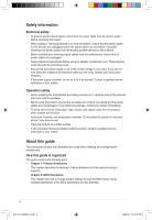
are using, contact your local power company. • If the power supply is broken, do not try to fix it by yourself. Contact a qualified service technician or your retailer. Operation safety • Before installing the motherboard and adding devices on it, carefully read all the manuals that came with the - Asus AT5NM10T-I | User Manual - Page 7
IMPORTANT: Instructions that you MUST follow to complete a task. NOTE: Tips and additional information to help you complete a task. Where to find more information Refer to the following sources for additional information and for product and software updates. 1. ASUS websites The ASUS website - Asus AT5NM10T-I | User Manual - Page 8
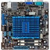
Audio LAN USB ASUS special features Rear panel ports Integrated Dual-Core Intel® Atom™ D510 processor Intel® NM10 Single channel memory architecture - 2 x 240-pin DIMM sockets support maximum 4GB unbuffered non-ECC 800/667 MHz DDR2 memory modules * Refer to www.asus.com or this user manual - Asus AT5NM10T-I | User Manual - Page 9
audio connector 1 x 24-pin EATX power connector 1 x 4-pin ATX 12V power connector 8 Mb Flash ROM, AMI BIOS, PnP, DMI2.0, WfM2.0, SMBIOS 2.5 1 x Serial ATA cable 1 x I/O shield 1 x User Manual Drivers ASUS PC Probe II ASUS Update Anti-virus software (OEM version) Mini ITX form factor: 6.75 in x 6.75 - Asus AT5NM10T-I | User Manual - Page 10
Chapter 1 Product introduction Thank you for buying an ASUS® AT5NM10-I motherboard! Before you start installing the motherboard, and hardware devices on it, check the items in your motherboard package. Refer to page ix for the list of accessories. If any of the items is damaged or missing, contact - Asus AT5NM10T-I | User Manual - Page 11
. DO NOT overtighten the screws! Doing so can damage the motherboard. 1.2.2 Layout contents Connectors/Jumpers/Slots/LED Page Connectors/Jumpers/Slots/LED Page Keyboard/mouse power and USB device 1. wake-up (3-pin PS2_USBPW1-4, 3-pin USBPW5- 1-10 9. 8) Chassis intrusion connector (4-1 pin - Asus AT5NM10T-I | User Manual - Page 12
Central Processing Unit (CPU) The motherboard comes with an onboard Dual-Core Intel® Atom™ D510 processor and a specially designed CPU heatsink. Ensure that the CPU fan cable is connected to the onboard CPU_FAN connector. 1.4 System memory 1.4.1 Overview The motherboard comes with two Double Data - Asus AT5NM10T-I | User Manual - Page 13
• This motherboard does not support DIMMs made up of 256 megabits (Mb) chips or less. AT5NM10-I Motherboard Qualified Vendors - DIMM support A* B* • • • • - • - • - • 1.8V • 1.8V • - • - • - • - • - • - • - • - • - • - • - • - • ASUS AT5NM10-I 1-4 - Asus AT5NM10T-I | User Manual - Page 14
3SP0717A DS takeMS MS18T51280-3 DS UMAX DS UMAX U2S12D30YP-6E U2S24D30TP-6E Timing 4 4 5 Voltage - DIMM support A* B* • • • • • • • 5 - • 5 - • 5 - • 5 - • - - • 5 - • DDR2-800 MHz capability Vendor A-Data A-Data A-Data A-Data Corsair Corsair Corsair Corsair Crucial Crucial - Asus AT5NM10T-I | User Manual - Page 15
-HCF7 K4T2G084QA-HCF7 - DIMM Timing Voltage support A* B* 5 - •• 4 - •• 5 - •• 5 1.8V • • 4 - •• 5 - •• 5 - •• 4 - •• 5 - - - •• 6 - •• 6 - •• - - •• 4 1.8V • • (continued on the next page) ASUS AT5NM10-I 1-6 E5179_AT5NM10-I.indb 6 12/22/09 5:55:50 PM - Asus AT5NM10T-I | User Manual - Page 16
8115 DS Hynix HY5PS12821CFP-S5 SS Elixir N2TU16800E-AC DIMM Timing Voltage support A* B* 5 - •• 5 - •• 5 - •• 5 - •• support: • A*: Supports one module inserted into either slot. • B*: Supports one pair of modules inserted into both the slots. Visit the ASUS website at www.asus - Asus AT5NM10T-I | User Manual - Page 17
for information on BIOS setup. 2. Assign an IRQ to the card. 3. Install the software drivers for the expansion card. 1.5.3 PCI slot The PCI slot supports cards such as a LAN card, SCSI card, USB card, and other cards that comply with PCI specifications. ASUS AT5NM10-I E5179_AT5NM10-I.indb 8 1-8 12 - Asus AT5NM10T-I | User Manual - Page 18
about 5-10 seconds, then move the cap back to pins 1-2. 3. Plug the power cord and turn ON the computer. 4. Hold down the key during the boot process and enter BIOS setup to re-enter data. Except when clearing the RTC RAM, never remove the cap on CLRTC jumper default position. Removing the cap - Asus AT5NM10T-I | User Manual - Page 19
+5V +5VSB (Default) AT5NM10-I Keyboard Power Setting The total current consumed must NOT exceed the power supply capability (+5VSB) whether under normal condition or in sleep mode. 3. USB device wake-up (3-pin USBPW5-8) Set this jumper to +5V to wake up the computer from S1 sleep mode (CPU stopped - Asus AT5NM10T-I | User Manual - Page 20
Mbps connection 100 Mbps connection 1 Gbps connection ACT/LINK SPEED LED LED LAN port 4. Line In port (light blue). This port connects to the Speaker Out Bass/Center 7. USB 2.0 ports 1 and 2. These two 4-pin Universal Serial Bus (USB) ports are for USB 2.0 devices. 1-11 E5179_AT5NM10-I.indb - Asus AT5NM10T-I | User Manual - Page 21
system will not boot up. • If you are uncertain about the minimum power supply requirement for your system, refer to the Recommended Power Supply Wattage Calculator at http://support.asus. com/PowerSupplyCalculator/PSCalculator.aspx?SLanguage=en-us for details. ASUS AT5NM10-I E5179_AT5NM10-I.indb - Asus AT5NM10T-I | User Manual - Page 22
/s is faster than the standard parallel ATA (133 MB/s). Install the Windows® XP Service Pack 2 or later versions before using Serial ATA. 3. USB connector (10-1 pin USB56, USB78) These connectors are for USB 2.0 ports. Connect the USB module cable to this connector, then install the module to a slot - Asus AT5NM10T-I | User Manual - Page 23
speaker connector (4-pin SPEAKER) The 4-pin connector is for the chassis-mounted system warning speaker. The speaker allows you to hear system beeps and warnings. ASUS AT5NM10-I E5179_AT5NM10-I.indb 14 1-14 12/22/09 5:56:02 PM - Asus AT5NM10T-I | User Manual - Page 24
the fan connectors. Insufficient air flow inside the system may damage the motherboard components. These are not jumpers! Do not place jumper caps on the This connector is for a chassis-mounted front panel audio I/O module that supports either HD Audio or legacy AC`97 audio standard. Connect one end - Asus AT5NM10T-I | User Manual - Page 25
system in sleep or soft-off mode depending on the BIOS settings. Pressing the power switch for more than four seconds while the system is power. 9. LVDS connector (30-pin CON1) This connector is for a LCD monitor that supports Low-voltage differential signaling (LVDS) interface. ASUS AT5NM10-I - Asus AT5NM10T-I | User Manual - Page 26
S/PDIF Out module cable to this connector, then install the module to a slot opening at the back of the system chassis. +5V SPDIFOUT GND AT5NM10-I Digital audio connector The S/PDIF module is purchased separately. 1-17 E5179_AT5NM10-I.indb 17 Chapter 1: Product introduction 12/22/09 5:56:07 PM - Asus AT5NM10T-I | User Manual - Page 27
you install Windows® XP Service Pack 3 or later versions / Windows® Vista Service Pack 1 or later versions before installing the drivers for better compatibility and system stability. 1.8.2 Support DVD information The Support DVD that comes with the motherboard package contains the drivers, software - Asus AT5NM10T-I | User Manual - Page 28
is available in the support DVD that comes with the motherboard package. Installing ASUS Update To install ASUS Update: 1. Place the support DVD in the optical drive. The Drivers menu appears. 2. Click the Utilities tab, then click ASUS Update. 3. Follow the onscreen instructions to complete the - Asus AT5NM10T-I | User Manual - Page 29
to avail all its features. Updating from a BIOS file a. Select Update BIOS from a file, then click Next. b. Locate the BIOS file from the Open window, then click Open. 3. Follow the onscreen instructions to complete the updating process. 2.1.2 ASUS EZ Flash 2 The ASUS EZ Flash 2 feature allows you - Asus AT5NM10T-I | User Manual - Page 30
while updating the BIOS to prevent system boot failure! 2.1.3 ASUS CrashFree BIOS The ASUS CrashFree BIOS is an auto recovery tool that allows you to restore the BIOS file when it fails or gets corrupted during the updating process. You can restore a corrupted BIOS file using the motherboard support - Asus AT5NM10T-I | User Manual - Page 31
. • Visit the ASUS website at www.asus.com to download the latest BIOS file for this motherboard. 2.3 Main menu When you enter the BIOS Setup program, the Main menu screen appears, giving you an overview of the basic system information. Main Advanced Power BIOS SETUP UTILITY Boot Tools Exit - Asus AT5NM10T-I | User Manual - Page 32
date. 2.3.3 SATA 1/2 While entering Setup, the BIOS automatically detects the presence of SATA devices. There DMA, and SMART Monitoring). These values are not user-configurable. These items show Not Detected if no Auto] enables the LBA mode if the device supports this mode, and if the device was not - Asus AT5NM10T-I | User Manual - Page 33
SATA as [IDE] Sets the configuration for the Serial ATA connectors supported by the Southbridge chip. Configuration options: [IDE] [AHCI] [ Power BIOS SETUP UTILITY Boot Tools Exit CPU Configuration Chipset Onboard Devices Configuration USB Configuration PCIPnP Configure CPU. ASUS AT5NM10-I - Asus AT5NM10T-I | User Manual - Page 34
BIOS automatically detects. Max CPUID Value Limit [Disabled] Allows you to determine whether to limit CPUID maximum value. Set this item to [Disabled] for Windows XP use as the primary boot device. Configuration options: Enabled, 4MB] [Enabled, 8MB] Video Function Configruation DVMT Mode Select [DVMT - Asus AT5NM10T-I | User Manual - Page 35
LAN controller. Configuration options: [Enabled] [Disabled] Onboard LAN Boot ROM [Disabled] Allows you to enable or disable the boot ROM in the onboard LAN controller. This item appears only when the Onboard LAN options: [IRQ5] [IRQ7] ASUS AT5NM10-I E5179_AT5NM10-I.indb 8 2-8 12/22/09 5:56:16 PM - Asus AT5NM10T-I | User Manual - Page 36
USB 2.0 controller. Configuration options: [Enabled] [Disabled] Legacy USB Support [Auto] Allows you to enable or disable support for Legacy USB storage devices, including USB flash drives and USB set the maximum time that the BIOS waits for the USB storage device to initialize. Configuration options - Asus AT5NM10T-I | User Manual - Page 37
Advanced Power BIOS SETUP UTILITY Boot Tools Exit Suspend Mode [S3 only] ACPI 2.0 Support [Disabled] ACPI APIC Support [ Suspend to RAM) sleep state (default). In S3 sleep state, the system appears to be off and consumes less power than in the S1 state. When signaled by a wake-up device - Asus AT5NM10T-I | User Manual - Page 38
requires an ATX power supply that provides at least 1A on the +5VSB lead. Configuration options: [Disabled] [Enabled] 2.5.5 Hardware Monitor CPU/MB Temperature [xxxºC/xxxºF] or [Ignored] The onboard hardware monitor automatically detects and displays the CPU/motherboard temperature. Select Ignored - Asus AT5NM10T-I | User Manual - Page 39
appears. • To access Windows® OS in Safe Mode, do any of the following: • Press when ASUS Logo appears. • Press after POST. 2.6.2 Boot Settings Configuration Quick Boot [Enabled] Enabling this item allows the BIOS to skip some power on self tests (POST) while booting to decrease the - Asus AT5NM10T-I | User Manual - Page 40
> twice. The message Password uninstalled appears. If you forget your BIOS password, you can clear it by erasing the CMOS Real Time Clock (RTC) RAM. See section 1.6 Jumpers for information on how to erase the RTC RAM. 2-13 E5179_AT5NM10-I.indb 13 Chapter 2: BIOS information 12/22/09 5:56:20 PM - Asus AT5NM10T-I | User Manual - Page 41
Check [Setup] When set to [Setup], BIOS checks for user password when accessing the Setup utility. When set to [Always], BIOS checks for user password both when accessing Setup and booting the system. Configuration options: [Setup] [Always] ASUS AT5NM10-I E5179_AT5NM10-I.indb 14 2-14 12/22/09 - Asus AT5NM10T-I | User Manual - Page 42
> to display the sub-menu. Main Advanced Power BIOS SETUP UTILITY Boot Tools Exit ASUS EZ Flash 2 Express Gate Enter OS Timer Reset User Data AI NET2 [Auto] [10 Seconds] [No] Press ENTER to run the utility to select and update BIOS. This utility supports 1.FAT 12/16/32(r/w) 2.NTFS(read only - Asus AT5NM10T-I | User Manual - Page 43
LAN cable during the Power-On Self‑Test (POST). Configuration options: [Disabled] [Enabled] 2.8 Exit menu The Exit menu items allow you to load the optimal or failsafe default values for the BIOS -eEfreopiemslxonntecpimnrtetheisn ASUS AT5NM10-I E5179_AT5NM10
-
 1
1 -
 2
2 -
 3
3 -
 4
4 -
 5
5 -
 6
6 -
 7
7 -
8
-
9
-
10
-
11
-
12
-
13
-
14
-
15
-
16
-
17
-
18
-
19
-
20
-
21
-
22
-
23
-
24
-
25
-
26
-
27
-
28
-
29
-
30
-
31
-
32
-
33
-
34
-
35
-
36
-
37
-
38
-
39
-
40
-
41
-
42
-
43
 |
 |

Motherboard
AT5NM10-I
E5179_AT5NM10-I.indb
1
12/22/09
5:55:35 PM