Asus GigaX 1124i User Manual
Asus GigaX 1124i Manual
 |
View all Asus GigaX 1124i manuals
Add to My Manuals
Save this manual to your list of manuals |
Asus GigaX 1124i manual content summary:
- Asus GigaX 1124i | User Manual - Page 1
Centralized Network Management GigaX Smart Switch Management Software User's Manual E1816 / Oct 2004 - Asus GigaX 1124i | User Manual - Page 2
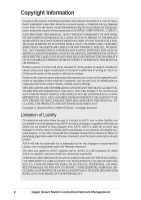
LIKE), EVEN IF ASUS HAS BEEN ADVISED OF THE POSSIBILITY OF SUCH DAMAGES ARISING FROM ANY DEFECT OR ERROR IN THIS MANUAL OR PRODUCT. Product warranty or service will not be extended if: (1) the product is repaired, modified or altered, unless such repair, modification of alteration is authorized in - Asus GigaX 1124i | User Manual - Page 3
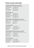
Telephone: +886-2-2894-3447 General Fax: +886-2-2894-7798 Web Site Address: www.asus.com.tw General Email: [email protected] Technical Support MB/Others (Tel): +886-2-2890-7121 Notebook (Tel): +886-2-2894-3447 Desktop/Server (Tel): +886-2-2890-7123 Networking (Tel): +886-2-2890-7902 - Asus GigaX 1124i | User Manual - Page 4
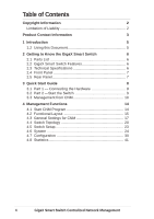
Switch 6 2.1 Parts List 6 2.2 GigaX Smart Switch Features 6 2.3 Technical Specifications 6 2.4 Front Panel 7 2.5 Rear Panel 7 3 Quick Start Guide 8 3.1 Part 1 - Connecting the Hardware 8 3.2 Part 2 -Start the Switch 9 3.3 Management from CNM 10 4 Management Functions 14 4.1 Start - Asus GigaX 1124i | User Manual - Page 5
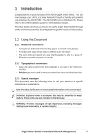
runs on Windows OS. Please refer to the CNM installation guide for CM installation details. This User Guide will show you how to set up the GigaX Smart the following icons to call your attention to specific instructions or explanations. Note: Provides clarification or nonessential information - Asus GigaX 1124i | User Manual - Page 6
with 6 screws (M3 x 6L)) • Installation CD-ROM • Quick installation guide 2.2 GigaX Smart Switch Features • (24) 10/100BASE-TX auto-sensing VLAN, up to 32 VLANs • 802.1p CoS (Class of Service), 2 queues per port • IGMP(v1, v2) snooping support • 802.3ad link aggregation (trunking), up to 7 trunk - Asus GigaX 1124i | User Manual - Page 7
2.4 Front Panel The front panel contains LED indicators that show the status of the unit. I Label POWER Color Green Off Light On Function The switch is powered on and operate normally The switch is powered off 10/100 ports from 1 to 24 STATUS / SPEED Green Amber DUPLEX/COLLISION Amber On - Asus GigaX 1124i | User Manual - Page 8
2 provides instructions to set up the hardware. • Part 3 shows you how to configure basic settings on the GigaX Smart Switch. This Quick Start Guide assumes that The switch should be installed on a level surface that can support the weight of the switches and their accessories. Attach four rubber - Asus GigaX 1124i | User Manual - Page 9
3.2 Part 2 -Start the Switch In Part 2, this guide will show you how to connect the switch to a power outlet CNM software that is running on a Windows OS computer. Please refer to the CNM installation guide for details. Before starting the CNM application, you have to connect the PC to the same network - Asus GigaX 1124i | User Manual - Page 10
LED Indicators This LED POWER STATUS of 10/100 ports STATUS of Gigabit ports (GigaX 1024P only) Should be Solid green to indicate that the device is turned on. If this light is not on, check if the power cord is attached to the switch and if it is plugged into a power source. Solid green/amber to - Asus GigaX 1124i | User Manual - Page 11
Figure 3.2 CNM Outlook (GigaX 1024P) Figure 3.2.1 CNM Outlook (GigaX 1024I) GigaX Smart Switch Centralized Network Management 11 - Asus GigaX 1124i | User Manual - Page 12
3. Select the proper NIC at the same network with the switch, then click on the Discovery icon in the tool bar. After the discovery is done, the left frame of the window will show the MAC addresses of the switches discovered by the CNM as shown below. Figure 3.3 Available Switches (GigaX 1024P) - Asus GigaX 1124i | User Manual - Page 13
4. Select the switch you want to manage by clicking on the MAC address, then you can start to configure the switch by CNM. 5. If the CNM cannot discover the switch you want to manage, please repeat step 1 to 4 again. Note: The switch must be powered on and connect to your network before starting the - Asus GigaX 1124i | User Manual - Page 14
to work best with Microsoft Windows operation system. 4.1 Start CNM Program 1. Install CNM in a computer running Windows OS. Refer to CNM installation guide for detail installation steps. 2. The computer with CNM installed must be in the same network as the switches are. 3. Make sure the switches - Asus GigaX 1124i | User Manual - Page 15
4.2 Functional Layout The CNM window consists of three separate frames. The top frame has switch logo and front panel as shown below. This frame remains on the top of the browser window all the times and updates the LED status periodically. The LED definition has been described in Table 3.1. Each - Asus GigaX 1124i | User Manual - Page 16
The left frame, a topology frame as shown in Figure 4.3, contains all the NICs in the manage station. Each NIC has a tree view to show the switches that are discovered by CNM. You can click on any of these to display a specific configuration of the switch. Figure 4.3 A Topology Frame Click on the - Asus GigaX 1124i | User Manual - Page 17
for CNM. • The Topology item provides the general network discovery, manually add or delete switches, and load or save the current discovered topology password settings. • The Help item provides CNM information and instructions 4.3.1 Topology Figure 4.5 Topology Topology is to control the actions - Asus GigaX 1124i | User Manual - Page 18
Add Switch: add a switch to the topology tree manually. A window will show for this purpose as shown if you don't use the default one (2379), then click OK to finish the action. However, a manually added switch does not mean it can be configured or discovered by CNM. The function provides a way to - Asus GigaX 1124i | User Manual - Page 19
6. Remove Switch: you can remove any switch in the topology list manually through this function. It pops out a switch list and check those switches you want to remove. Please refer to Figure 4.7 for the switch list window. 4.3.2 - Asus GigaX 1124i | User Manual - Page 20
4.4 Switch Topology The switch topology frame is on the left part of the CNM window. It shows the discovered switches and the relationship among them. Each presents a NIC interface. The interface name and MAC address is shown after the. The switch topology shows the relationship among the switches - Asus GigaX 1124i | User Manual - Page 21
a switch under it. 2. Switch: check the box if you want the new switch to be added under a specified switch in the topology tree. The manually added switch will be moved to a right place to show the relationships in the topology after a successful discovery. 3. MAC: the most important information is - Asus GigaX 1124i | User Manual - Page 22
of the CNM window, and the topology tree will display the switch symbol in a correct place to show the relationship. If CNM cannot discover the manually added switch, then a will attach to the switch to show it is not reachable to the CNM. Figure 4.12 shows the window to remove switches - Asus GigaX 1124i | User Manual - Page 23
4.5 Switch Setup Before using the configuration windows, it is better to know following buttons or icons because they are used throughout the setup. The following table describes the function for each button or icon. Table 4.1 2 Description of Commonly Used Buttons Buttons Function Apply to the - Asus GigaX 1124i | User Manual - Page 24
4.6 System The system menu provides reboot, link status, and change password. 4.6.1 Reboot Hardware and software reset functions are provided. Hardware reset returns the system to its initial state just like power on hardware reset. Note: Hardware reset will clear all configuration settings. - Asus GigaX 1124i | User Manual - Page 25
4.6.2 Link Status Link status table shows the port information including speed, duplex mode and flow control. Click on the Reload button will get the update information. Figure 4.14 shows the status table. Figure 4.14 Link Status (GigaX 1024P) Figure 4.14.1 Link Status (GigaX 1024I) GigaX Smart - Asus GigaX 1124i | User Manual - Page 26
administrators to save the topology or not. If not, administrators will have to do two jobs when CNM starts up next time. First, manually add the switch according to section 4.4.2. Second, change password again and replace 0x2379 with correct one. Figure 4.14.2 Change Password (GigaX 1024P) Figure - Asus GigaX 1124i | User Manual - Page 27
4.6.4 Load You can load configuration from the switch or the local file as shown below. This action will update the current configuration in the CNM. If you want to keep the current configuration, please refer to section 4.6.5. Figure 4.15 Load (GigaX 1024P) Figure 4.15.1 Load (GigaX 1024I) GigaX - Asus GigaX 1124i | User Manual - Page 28
4.6.5 Save Save all the configurations to a local file for future reference. Once you create a configuration file in CNM, you can use it to apply to the other switches to save your time. It is also a backup file for configuration. It is recommended to have a good file name to identify that the - Asus GigaX 1124i | User Manual - Page 29
4.6.6 Apply and Save It applies all the current settings in CNM to the switch and save them in the switch permanently. It is recommended to back up the existed switch configurations before applying a new configuration to the switch. Figure 4.17 Apply Configuration (GigaX 1024P) Figure 4.17.1 Apply - Asus GigaX 1124i | User Manual - Page 30
4.7 Configuration The Configuration menu provides the configuration for all the functions that the switch can supports, like physical interface, link aggregation, bandwidth control, traffic control, VLAN, IGMP snooping and QoS. To keep all the new configurations and save the bandwidth for - Asus GigaX 1124i | User Manual - Page 31
Figure 4.18.1 Physical Interface (GigaX 1024I) Above shows the configuration for each port. Select the ports you want to configure or reload information from the switch by clicking on the check boxes in front of the ports, then click on Config to set the configuration for the ports, or click on - Asus GigaX 1124i | User Manual - Page 32
4.7.2 Link Aggregation Figure 4.19 Link Aggregation (GigaX 1024P) Figure 4.19.1 Link Aggregation (GigaX 1024I) 32 GigaX Smart Switch Centralized Network Management - Asus GigaX 1124i | User Manual - Page 33
Link aggregation creates new virtual links with more bandwidth. For example, port 1 and 2 can work together as one link to another device. The new virtual link has 200Mbps bandwidth. The switch provides 8 groups (GigaX 1024P) or 7 groups (GigaX 1024I) of link aggregations shown above. Click on the - Asus GigaX 1124i | User Manual - Page 34
Figure 4.20.1 Bandwidth Configuration (GigaX 1024I) GigaX Smart Switch provides TX/RX bandwidth control for each port. Please reload the configuration before you start to set up new configuration. The page is shown above. Select the ports you want to configure, then select proper bandwidth for TX/RX - Asus GigaX 1124i | User Manual - Page 35
4.7.4 Traffic Control Traffic control is to set the following items 1. Broadcast storm filtering control: if enabled, each port start to drop broadcast packets after a continuous received broadcast packets count up to 64. It will be back to normal if no more broadcast packet is received in 800ms or - Asus GigaX 1124i | User Manual - Page 36
Figure 4.21 VLAN (GigaX 1024P) Figure 4.21.1 VLAN (GigaX 1024I) 36 GigaX Smart Switch Centralized Network Management - Asus GigaX 1124i | User Manual - Page 37
All VLAN behavior will be influenced by VLAN control option. Click Control Option and a window will appear as shown as below. Enable or disable these options carefully, these options are global setting for VLAN Figure 4.22 VLAN Control Options 7. VLAN function: enable or disable the VLAN function. - Asus GigaX 1124i | User Manual - Page 38
4.7.6 IGMP Snooping Enable the IGMP snooping will let the switch learn the multicast router port and group address member ports into the multicast address table. The table is combined with L2 MAC table, so the maximum entry is 8K. The valid port member will auto aging out after about 5 minute idle. - Asus GigaX 1124i | User Manual - Page 39
4.7.7 QoS Setup The system support 2 level priority queues. The queue service rate is based on the packet-based Weighted Round Robin algorithm. The ratio can be set as 4:1, 8:1, 16:1, or strictly high priority first. The port- - Asus GigaX 1124i | User Manual - Page 40
Figure 4.24.1 QoS Setup (GigaX 1024I) 40 GigaX Smart Switch Centralized Network Management - Asus GigaX 1124i | User Manual - Page 41
4.8 Statistics Statistics offer Port Traffic, Traffic History and Comparison charts. The switch has 3 counters for 8 kinds of statistics. So you cannot see all the statistics at the same time. That is, the old statistics data will be gone if you start to use the counter for another statistics. 4.8.1 - Asus GigaX 1124i | User Manual - Page 42
4.8.2 Traffic History Select the statistics item, ports and colors you want to see in the chart, then press the Draw Traffic Chart button to start the drawing. The chart will be auto updated in the time interval you set in Setup menu. Refer to 4.3.2 for time interval setup. Figure 4.26 Traffic - Asus GigaX 1124i | User Manual - Page 43
4.8.3 Comparison Select the statistics item to do comparison for port 1 to 26 (ports 25-26 on GigaX 1024P only). Press the Draw Traffic Chart button to start the drawing. The chart will be auto updated in the time interval you set in Setup menu. Figure 4.27 Port Comparison (GigaX 1024P) Figure 4. - Asus GigaX 1124i | User Manual - Page 44
44 GigaX Smart Switch Centralized Network Management
-
 1
1 -
 2
2 -
 3
3 -
 4
4 -
 5
5 -
 6
6 -
 7
7 -
8
-
9
-
10
-
11
-
12
-
13
-
14
-
15
-
16
-
17
-
18
-
19
-
20
-
21
-
22
-
23
-
24
-
25
-
26
-
27
-
28
-
29
-
30
-
31
-
32
-
33
-
34
-
35
-
36
-
37
-
38
-
39
-
40
-
41
-
42
-
43
-
44
 |
 |

Centralized Network
Management
GigaX Smart Switch Management Software
User’s Manual
E1816 / Oct 2004