Asus K8N-DRE User Guide
Asus K8N-DRE - Motherboard - Extended ATX Manual
 |
UPC - 610839132164
View all Asus K8N-DRE manuals
Add to My Manuals
Save this manual to your list of manuals |
Asus K8N-DRE manual content summary:
- Asus K8N-DRE | User Guide - Page 1
K8N-DRE Motherboard - Asus K8N-DRE | User Guide - Page 2
for backup purposes, without the express written permission of ASUSTeK COMPUTER INC. ("ASUS"). Product warranty or service will not be extended if: A COMMITMENT BY ASUS. ASUS ASSUMES NO RESPONSIBILITY OR LIABILITY FOR ANY ERRORS OR INACCURACIES THAT MAY APPEAR IN THIS MANUAL, INCLUDING THE PRODUCTS - Asus K8N-DRE | User Guide - Page 3
ix K8N-DRE specifications summary x Chapter 1: Product introduction 1.1 Welcome 1-1 1.2 Package contents 1-1 1.3 Special features 1-2 1.3.1 Product highlights 1-2 1.3.2 Innovative ASUS features 1-4 Chapter 2: Hardware information 2.1 Before you proceed 2-1 Onboard LEDs 2-1 2.2 Motherboard - Asus K8N-DRE | User Guide - Page 4
Using the dual function power switch 3-2 Chapter 4: BIOS setup 4.1 Managing and updating your BIOS 4-1 4.1.1 Creating a bootable floppy disk 4-1 4.1.2 AFUDOS utility 4-2 4.1.3 ASUS CrashFree BIOS 2 utility 4-5 4.1.4 ASUS Update utility 4-7 4.2 BIOS setup program 4-10 4.2.1 BIOS menu screen - Asus K8N-DRE | User Guide - Page 5
6.1 RAID driver installation 6-1 Creating a RAID driver disk 6-1 6.3 LAN driver installation 6-3 6.4 Support CD information 6-4 6.4.1 Running the support CD 6-4 6.4.2 Drivers menu 6-5 6.4.3 Management Software 6-6 6.4.4 Utilities 6-7 Appendix: Reference information A.1 K8N-DRE block diagram - Asus K8N-DRE | User Guide - Page 6
and, if not installed and used in accordance with manufacturer's instructions, may cause harmful interference to radio communications. However, there is reception, which can be determined by turning the equipment off and on, the user is encouraged to try to correct the interference by one or more of - Asus K8N-DRE | User Guide - Page 7
are using, contact your local power company. • If the power supply is broken, do not try to fix it by yourself. Contact a qualified service technician or your retailer. Operation safety • Before installing the motherboard and adding devices on it, carefully read all the manuals that came with the - Asus K8N-DRE | User Guide - Page 8
guide This user guide contains the information you need when installing and configuring the motherboard. How this guide is organized This manual contains the following parts: • Chapter 1: Product introduction This chapter describes the features of the motherboard and the new technology it supports - Asus K8N-DRE | User Guide - Page 9
manual. D A N G E R / W A R N I N G : Information to prevent injury to yourself when trying to complete a task. C A U T I O N : Information to prevent damage to the components when trying to complete a task. I M P O R T A N T : Instructions shown, then supply the required item or value enclosed in - Asus K8N-DRE | User Guide - Page 10
K8N-DRE specifications summary CPU Chipset System Bus Memory Expansion slots Storage Dual Socket 940 for AMD Opteron™ 64 processors Supports AMD 64 architecture that enables simultaneous 32-bit and 64-bit computing NVIDIA® nForce Professional 2200 1600/2000 MT per second Dual-channel memory - Asus K8N-DRE | User Guide - Page 11
K8N-DRE specifications summary Internal connectors Form Factor Support CD contents 1 x Floppy disk drive connector 2 x IDE connectors 4 x Serial ATA connectors 1 x 68-pin SCSI connector (SCSI models only) 6 x Front fan connector 4 x Rear fan connector 1 x 24-pin ATX power connector 1 x 8-pin ATX - Asus K8N-DRE | User Guide - Page 12
xii - Asus K8N-DRE | User Guide - Page 13
This chapter describes the motherboard features and the new technologies it supports. 1Product introduction - Asus K8N-DRE | User Guide - Page 14
Chapter summary 1.1 Welcome 1-1 1.2 Package contents 1-1 1.3 Special features 1-2 ASUS K8N-DRE - Asus K8N-DRE | User Guide - Page 15
(dual plugs) 1 x SCSI Ultra320 cable (SCSI model only) 1 x 3-in-1 IDE and floppy cable I/O shield 2 x Copper heatsink 2 x Support plates for CPU 2 x Adhesive pads 4 x Screws ASUS motherboard support CD User guide If any of the above items is damaged or missing, contact your retailer. ASUS K8N-DRE - Asus K8N-DRE | User Guide - Page 16
The motherboard comes with dual 940-pin sockets for the AMD Opteron™ 64 processors. The processors are based on AMD's 64-bit and 32-bit architecture, which represents the landmark introduction of the industry's first x86-64 technology, provide a dramatic leap forward in compatibility, performance - Asus K8N-DRE | User Guide - Page 17
overheating and damage. The system fan rotations per minute (RPM) is monitored for timely failure detection. The ASIC monitors the voltage levels to ensure stable supply of current for critical components. See section "4.4.8 Hardware Monitor" on page 4-27. ASUS K8N-DRE 1-3 - Asus K8N-DRE | User Guide - Page 18
allows you to restore the original BIOS data from the support CD in case when the BIOS codes and data are corrupted. This protection eliminates the need to buy a replacement ROM chip. See details on page 4-5. ASUS MyLogo2™ This new feature present in the motherboard allows you to personalize and add - Asus K8N-DRE | User Guide - Page 19
This chapter lists the hardware setup procedures that you have to perform when installing system components. It includes description of the jumpers and connectors on the motherboard. 2 Hardware information - Asus K8N-DRE | User Guide - Page 20
Chapter summary 2.1 Before you proceed 2-1 2.2 Motherboard overview 2-2 2.3 Central Processing Unit (CPU 2-9 2.4 System memory 2-12 2.5 Expansion slots 2-16 2.6 Jumpers 2-18 2.7 Connectors 2-22 ASUS K8N-DRE - Asus K8N-DRE | User Guide - Page 21
that a processor is not installed or the processor is not installed properly in CPU 1 socket. CPU_WARN1 K8N-DRE ® ON No CPU installed No CPU on socket CPU1 CPU types mismatched OFF No detected CPU problem K8N-DRE Standby power LED SB_PWR1 ON Standby Power OFF Powered Off ASUS K8N-DRE 2-1 - Asus K8N-DRE | User Guide - Page 22
the image below. 2.2.2 Screw holes Place ten (10) screws into the holes indicated by circles to secure the motherboard to the chassis. Do not overtighten the screws! Doing so can damage the motherboard. Place this side towards the rear of the chassis K8N-DRE ® 2-2 Chapter 2: Hardware information - Asus K8N-DRE | User Guide - Page 23
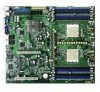
J1 RECOVERY1 K8N-DRE LAN2 BMCSOCKET1 BCM5721 LAN1 VGA1 COM1 USB12 KBMS1 KBPWR1 BCM5721 LAN2_EN1 LAN1_EN1 CPU_WARN1 LPT1 PCI1 PCIE1 4Mbit BIOS 68 34 ATI RAGE-XL VGA_EN1 LSI 1020A SCSI_EN1 35 1 CR2032 3V Lithium Cell CMOS Power CLRTC1 nVIDIA nForce Professional 2200 SATA2 - Asus K8N-DRE | User Guide - Page 24
Heatsink plates Two heatsink plates come with the motherboard package. These plates support the weight of the CPU heatsinks. To install the heatsink plates: 1. Peel off the adhesive pads that came with the motherboard package. Adhesive pad 2. Match the holes of the adhesive pad with the heatsink - Asus K8N-DRE | User Guide - Page 25
4. Peel off the adhesive pad cover. 5. Locate the heatsink holes on the motherboard. 6. Position the heatsink plate underneath the motherboard and match the motherboard CPU1 heatsink holes with the heatsink plate standoffs. 7. Press the heatsink plate flat under the motherboard. ASUS K8N-DRE 2-5 - Asus K8N-DRE | User Guide - Page 26
installed. Standoffs 8. Repeat steps 1-7 if you want to install a second processor in CPU2 socket. Even if you are not installing a second processor now, we recommend that you install the second heatsink plate. 9. Secure the motherboard with ten (10) screws. Refer to section "2.2.2 Screw Holes" for - Asus K8N-DRE | User Guide - Page 27
Slots/Sockets 1. CPU sockets 2. DDR DIMM sockets 3. PCI Express x16 slot Jumpers 1. Clear RTC RAM (CLRTC1) 2. Keyboard power (3-pin KBPWR1) 3. Gigabit LAN1 controller setting (3-pin LAN1_EN1) 4. Gigabit LAN2 controller setting (3-pin LAN2_EN1) 5. SCSI controller setting (3-pin SCSI_EN1) 6. BIOS - Asus K8N-DRE | User Guide - Page 28
SMBus connector (6-1 pin FPSMB) 8. USB connectors (10-1 pin USB34) 9. Serial port connector (10-1 pin COM2) 10. ATX power connectors (24-pin ATXPWR1, 8-pin ATX12V1) 11. Power supply SMBus connector (5-pin PSUSMB1) 12. Parallel port connector (26-1 pin LPT1) 13. System panel auxiliary connector (20 - Asus K8N-DRE | User Guide - Page 29
Locate the CPU socket on the motherboard. K8N-DRE ® CPU2 CPU1 CPU2 CPU1 K8N-DRE CPU Socket 940 • Before installing the CPU, make sure that the socket box is facing towards you and the load lever is on your left. • If installing only one CPU, use the CPU socket marked CPU1. ASUS K8N-DRE 2-9 - Asus K8N-DRE | User Guide - Page 30
force the CPU into the socket to prevent bending the pins and damaging the CPU! 5. When the CPU is in place, push down the socket lever to secure the CPU. The lever clicks on the side tab to indicate that it is locked. 6. Repeat steps 1-5 to install a second processor in CPU 2 socket. 2-10 Chapter - Asus K8N-DRE | User Guide - Page 31
that the screw holes are matched with the heatsink standoffs. 2. Secure the heatsink with two screws. Make sure that the heatsink is not skewed or tilted otherwise, the CPU will overheat. 3. If you installed a second processor, repeat steps 1-2 to install the second heatsink. ASUS K8N-DRE 2-11 - Asus K8N-DRE | User Guide - Page 32
The motherboard comes with eight 184-pin Double Data Rate (DDR) Dual Inline Memory Modules (DIMM) sockets. The following figure illustrates the location of the sockets: K8N-DRE ® DIMM_A1 DIMM_A2 DIMM_B1 DIMM_B2 DIMM_D2 DIMM_D1 DIMM_C2 DIMM_C1 104 Pins 80 Pins 80 Pins 104 Pins K8N-DRE 184 - Asus K8N-DRE | User Guide - Page 33
populated populated populated DIMM_B1 - - populated DIMM_B2 - populated populated Recommended memory configuration for CPU2 Mode Single channel Dual channel DIMM_C1 - - populated DIMM_C2 populated populated populated DIMM_D1 - - populated DIMM_D2 - populated populated ASUS K8N-DRE 2-13 - Asus K8N-DRE | User Guide - Page 34
If you install a processor with Rev. CG or C0 with DDR 400 DIMMs, some memory configurations may not run at 400MHz. Refer to table below for details. Mode Single channel (72 bits) Dual channel (144 bits) DIMM_A1/ DIMM_A2/ DIMM_C1 DIMM_C2 Single rank Double rank - - Single rank Single rank Double - Asus K8N-DRE | User Guide - Page 35
2.4.3 Installing a DIMM Make sure to unplug the power supply before adding or removing DIMMs or other system components. Failure to do so may cause severe damage to both the motherboard and the components. 1. Unlock a DIMM socket by pressing the retaining clips outward. 2. Align a DIMM on the - Asus K8N-DRE | User Guide - Page 36
support. Make sure to unplug the power cord before adding or removing expansion cards. Failure to do so may cause you physical injury and damage motherboard system unit cover (if your motherboard is already installed in a chassis BIOS settings, if any. See Chapter 4 for information on BIOS setup - Asus K8N-DRE | User Guide - Page 37
one PCI Express x16 graphics slot that complies with the PCI Express specifications. If your chassis supports a PCI Express riser card, install the riser card to support two PCI Express x8 cards. The figure shows a PCI Express riser card installed on the PCI Express x16 slot. ASUS K8N-DRE 2-17 - Asus K8N-DRE | User Guide - Page 38
. 5. Plug the power cord and turn ON the computer. 6. Hold down the key during the boot process and enter BIOS setup to re-enter data. Except when clearing the RTC RAM, never remove the cap on CLRTC jumper default position. Removing the cap will cause system boot failure! K8N-DRE ® CLRTC1 - Asus K8N-DRE | User Guide - Page 39
power supply that can supply at least 1A on the +5VSB lead, and a corresponding setting in the BIOS. K8N-DRE ® KBPWR1 1 2 +5VSB 2 3 +5V (Default) K8N-DRE Keyboard power the Gigabit LAN feature. K8N-DRE ® LAN1_EN1 1 2 Enable (Default) 2 3 Disable K8N-DRE LAN1_EN1 setting ASUS K8N-DRE 2-19 - Asus K8N-DRE | User Guide - Page 40
disable the onboard Broadcom® BCM5721 Gigabit LAN2 controller. Set to pins 1-2 to activate the Gigabit LAN feature. K8N-DRE ® LAN2_EN1 1 2 Enable (Default) 2 3 Disable K8N-DRE LAN2_EN1 setting 5 . SCSI controller setting (3-pin SCSI_EN1) These jumpers allow you to enable or disable the onboard - Asus K8N-DRE | User Guide - Page 41
) 2 3 BIOS recovery K8N-DRE BIOS recovery setting 7 . VGA Graphics controller setting (3-pin VGA_EN1) These jumpers allow you to enable or disable the onboard ATI Rage XL video graphics controller. Set to pins 1-2 to enable the video graphics controller. K8N-DRE ® K8N-DRE VGA setting ASUS K8N-DRE - Asus K8N-DRE | User Guide - Page 42
os for pointing devices or other serial devices. 5 . V i d e o p o r t . This port is for a VGA monitor or other VGA-compatible devices. 6 . L A N 1 ( R J - 4 5 ) p o r t . Supported by the BROADCOM® BCM5721 Gigabit LAN controller, this port allows Gigabit connection to a Local Area Network (LAN - Asus K8N-DRE | User Guide - Page 43
. This prevents incorrect insertion when you connect the IDE cable. • Use the 80-conductor IDE cable for Ultra DMA133/100/66 IDE devices. K8N-DRE 1 1 NOTE: Orient the red markings (usually zigzag) on the IDE ribbon cable to PIN 1. ® SEC_IDE1 PRI_IDE1 K8N-DRE IDE connectors ASUS K8N-DRE 2-23 - Asus K8N-DRE | User Guide - Page 44
Serial ATA connectors (7-pin SATA1, SATA2, SATA3, SATA4) Supported by the NVIDIA® nForce4™ chipset, these connectors are for the Serial ATA GND RSATA_RXN1 RSATA_RXP1 GND K8N-DRE ® SATA1 SATA4 GND RSATA_TXP4 RSATA_TXN4 GND RSATA_RXN4 RSATA_RXP4 GND K8N-DRE SATA connectors SATA3 GND RSATA_TXP3 - Asus K8N-DRE | User Guide - Page 45
card cable connected to the SCSI or SATA add-on card. The read or write activities of any device connected to the SCSI or SATA add-on card causes the front panel LED to light up. K8N-DRE ® HDLED1 1 NC ADD_IN_CARD_ACT# ADD_IN_CARD_ACT# NC K8N-DRE Hard disk activity LED connector ASUS K8N-DRE 2-25 - Asus K8N-DRE | User Guide - Page 46
sufficient air flow inside the system may damage the motherboard components. These are not jumpers! DO NOT place jumper caps on the fan connectors! • All fan features the ASUS Smart Fan technology. REAR_FAN1 REAR_FAN2 REAR_FAN3 REAR_FAN4 K8N-DRE Rotation +12V GND Rotation +12V GND Rotation +12V - Asus K8N-DRE | User Guide - Page 47
the USB 2.0 specification that supports up to 480 Mbps connection speed. K8N-DRE ® USB34 1 USB+5V USB_P3USB_P3+ GND USB+5V USB_P4USB_P4+ GND NC K8N-DRE USB 2.0 connector 9 . at the back of the system chassis. K8N-DRE ® COM2 PIN 1 K8N-DRE Serial port2 (COM2) connector ASUS K8N-DRE 2-27 - Asus K8N-DRE | User Guide - Page 48
or may not boot up if the power is inadequate. • Make sure that your power supply unit (PSU) can provide at least the minimum power required by your system. See the table below for details. ATXPWR1 24-pin Power Connector ATX12V1 8-pin K8N-DRE ® +3 Volts -12 Volts Ground PSON# Ground Ground - Asus K8N-DRE | User Guide - Page 49
interface. K8N-DRE ® PSUSMB1 PSU_I2CCLK PSU_I2CDATA NC GND +3.3V Remote Sense K8N-DRE Power supply SMBus K8N-DRE ® LPT1 Pin 1 STB# SPD0 SPD1 SPD2 SPD3 SPD4 SPD5 SPD6 SPD7 ACK# BUSY PE SLCT AFD# ERROR# PINIT# SLIN# GND GND GND GND GND GND GND GND K8N-DRE Parallel port connector ASUS K8N-DRE - Asus K8N-DRE | User Guide - Page 50
13. System panel auxiliary connector (20-pin AUX_PANEL1) This connector supports several server system functions. K8N-DRE ® K8N-DRE Auxiliary panel connector AUX_PANEL1 1 +5VSB CASEOPEN GND LOCATORLED1+ LOCATORLED1LOCATORBTN# GND LOCATORLED2LOCATORLED2+ NC I2CCLK_P2 GND I2CDATA_P2 +5VSB - Asus K8N-DRE | User Guide - Page 51
on the BIOS settings. Pressing the power switch for more than four seconds while the system is ON turns the system OFF. • Reset button (Blue 2-pin RESETBTN) This 2-pin connector is for the chassis-mounted reset button for system reboot without turning off the system power. ASUS K8N-DRE 2-31 - Asus K8N-DRE | User Guide - Page 52
2-32 Chapter 2: Hardware information - Asus K8N-DRE | User Guide - Page 53
This chapter describes the power up Powerin3g up sequence, the POST messages, and ways of shutting down the system. - Asus K8N-DRE | User Guide - Page 54
Chapter summary 3.1 Starting up for the first time 3-1 3.2 Powering off the computer 3-2 ASUS K8N-DRE - Asus K8N-DRE | User Guide - Page 55
30 seconds from the time you turned on the power, the system may have failed a power-on test. Check the jumper settings and connections or call your retailer for assistance. 7. At power on, hold down the key to enter the BIOS Setup. Follow the instructions in Chapter 4. ASUS K8N-DRE 3-1 - Asus K8N-DRE | User Guide - Page 56
Click O K. 3.2.2 Using the dual function power switch While the system is ON, pressing the power switch for less than four seconds BIOS setting. Pressing the power switch for more than four seconds lets the system enter the soft-off mode regardless of the BIOS setting. Refer to section "4.5 Power - Asus K8N-DRE | User Guide - Page 57
This chapter tells how to change the system settings through the BIOS Setup menus. Detailed descriptions of the BIOS parameters are also provided. 4 BIOS setup - Asus K8N-DRE | User Guide - Page 58
Chapter summary 4 4.1 Managing and updating your BIOS 4-1 4.2 BIOS setup program 4-10 4.3 Main menu 4-13 4.4 Advanced menu 4-19 4.5 Server menu 4-29 4.6 Security menu 4-31 4.7 Boot menu 4-34 4.8 Exit menu 4-37 ASUS K8N-DRE Series - Asus K8N-DRE | User Guide - Page 59
mode using a bootable floppy disk.) 2. A S U S C r a s h F r e e B I O S 2 (Updates the BIOS using a bootable floppy disk or the motherboard support CD when the BIOS file fails or gets corrupted.) 3. A S U S U p d a t e (Updates the BIOS in Windows® environment.) Refer to the corresponding sections - Asus K8N-DRE | User Guide - Page 60
. The actual BIOS screen displays may not be same as shown. 1. Copy the AFUDOS utility (afudos.exe) from the motherboard support CD to the bootable floppy disk you created earlier. 2. Boot the system in DOS mode, then at the prompt type: afudos /o[filename] where the [filename] is any user-assigned - Asus K8N-DRE | User Guide - Page 61
(www.asus.com) and download the latest BIOS file for the motherboard. Save the BIOS file to a bootable floppy disk. Write the BIOS filename on a piece of paper. You need to type the exact BIOS filename at the DOS prompt. 2. Copy the AFUDOS utility (afudos.exe) from the motherboard support CD to the - Asus K8N-DRE | User Guide - Page 62
the hard disk drive. A:\>afudos /iK8NDRE.ROM /pbnc AMI Firmware Update Utility - Version 1.19(ASUS V2.07(03.11.24BB)) Copyright (C) 2002 American Megatrends, Inc. All rights reserved. WARNING!! Do not turn off power during flash BIOS Reading file ....... done Reading flash ...... done Advance Check - Asus K8N-DRE | User Guide - Page 63
2 utility The ASUS CrashFree BIOS 2 is an auto recovery tool that allows you to restore the BIOS file when it fails or gets corrupted during the updating process. You can update a corrupted BIOS file using the motherboard support CD or the floppy disk that contains the updated BIOS file. • Prepare - Asus K8N-DRE | User Guide - Page 64
updating the BIOS! Doing so can cause system boot failure! 4. Restart the system after the utility completes the updating process. The recovered BIOS may not be the latest BIOS version for this motherboard. Visit the ASUS website (www.asus.com) to download the latest BIOS file. 4-6 Chapter 4: BIOS - Asus K8N-DRE | User Guide - Page 65
BIOS file • Download the latest BIOS file from the Internet • Update the BIOS from an updated BIOS file • Update the BIOS directly from the Internet, and • View the BIOS version information. This utility is available in the support CD that comes with the motherboard package. ASUS Update requires - Asus K8N-DRE | User Guide - Page 66
Updating the BIOS through the Internet To update the BIOS through the Internet: 1. Launch the ASUS Update utility from the Windows® desktop by clicking S t a r t > P r o g r a m s > A S U S > A S U S U p d a t e > A S U S U p d a t e. The ASUS Update main window appears. 2. Select U p d a t e B I O - Asus K8N-DRE | User Guide - Page 67
to download. Click Next. 5. Follow the screen instructions to complete the update process. The ASUS Update utility is capable of updating itself through the Internet. Always update the utility to avail all its features. Updating the BIOS through a BIOS file To update the BIOS through a BIOS file - Asus K8N-DRE | User Guide - Page 68
program This motherboard supports a programmable firmware chip that you can update using the provided utility described in section "4.1 Managing and updating your BIOS." Use the BIOS Setup program when you are installing a motherboard, reconfiguring your system, or prompted to "Run Setup". This - Asus K8N-DRE | User Guide - Page 69
Secondary IDE Master Secondary IDE Slave Tertiary IDE Master Fourth IDE Master Fifth IDE Master Sixth IDE Master System Information BIOS SETUP UTILITY Security Boot Exit [Mon, 06/27/2005] [08:52:30] [1.44 MB, 3.5 in Some of the navigation keys differ from one screen to another. ASUS K8N-DRE 4-11 - Asus K8N-DRE | User Guide - Page 70
other items (Advanced, Power, Boot, and Exit) ] [English] :[ST320413A] :[ASUS CD-S340] :[Not Detected] item that is not user-configurable. A configurable Memory [AGP/PCI] [ window Scroll bar At the top right corner of the menu screen is a brief description of the selected item. 4-12 Chapter 4: BIOS - Asus K8N-DRE | User Guide - Page 71
Secondary IDE Slave Tertiary IDE Master Fourth IDE Master Fifth IDE Master Sixth IDE Master System Information BIOS SETUP UTILITY Security Boot Exit [Mon, 06/27/2005] [08:52:30] [1.44 MB, ] [360K, 5.25 in.] [1.2M , 5.25 in.] [720K , 3.5 in.] [1.44M, 3.5 in.] [2.88M, 3.5 in.] ASUS K8N-DRE 4-13 - Asus K8N-DRE | User Guide - Page 72
the system. Select an item then press if you wish to configure the item. Main BIOS SETUP UTILITY IDE Configuration OnBoard PCI IDE Controller IDE DMA Transfer Configuration nVidia RAID ROM [Both] [Enabled] →← Select Screen ↑↓ Select Item +- Change Field Tab Select Field F1 General Help - Asus K8N-DRE | User Guide - Page 73
RAID Option ROM [Disabled] Enables or disables the NVIDIA® RAID option ROM. Configuration options: [Disabled] [Enabled] The following items appear when the RAID Sixth Master as RAID [Disabled] Sets the sixth master interface as RAID. Configuration options: [Disabled] [Enabled] ASUS K8N-DRE 4-15 - Asus K8N-DRE | User Guide - Page 74
the IDE device information. Main BIOS SETUP UTILITY Primary IDE Master S.M.A.R.T. monitoring). These values are not user-configurable. These items show N/A if if you are specifically configuring a CD-ROM drive. Select [ARMD] enables the LBA mode if the device supports this mode, and if the device - Asus K8N-DRE | User Guide - Page 75
automatically detects the items in this menu. Main BIOS SETUP UTILITY System Information Model Name Model ID ASUS K8N-DRE/SCSI 8009A0 ASUS BIOS Version Date 1001.007 06/09/2005 Processor System Memory →← Select Screen ↑↓ Select Item +- Change Field Tab Select Field F1 General Help F10 Save - Asus K8N-DRE | User Guide - Page 76
installed processor information. Main BIOS SETUP UTILITY Processor Information ***CPU1: Brand ID/uCode Ratio Cache Revision AMD Opteron(tm) Processor 240 - None Node1 Memory Configuration : Speed N/A DIMM05 - None DIMM06 - None DIMM07 - None DIMM08 - None BIOS SETUP UTILITY →← - Asus K8N-DRE | User Guide - Page 77
BIOS SETUP UTILITY Security Boot Exit WARNING: Setting wrong values in the sections below may cause system to malfunction. Options for CPU. CPU Configuration Chipset Configuration PCI [1.4] Sets the Multi-Processor System (MPS) table version. Configuration options: [1.1] [1.4] ASUS K8N-DRE 4-19 - Asus K8N-DRE | User Guide - Page 78
processor MTRRs when using more than 4GB of system memory. Configuration options: [Continuous] [Discrete] Cool 'n' Quiet [Enabled] Enables or disables the AMD® Cool 'n' Quiet! (Power Chipset Configuration NorthBridge Configuration SouthBridge Configuration BIOS SETUP UTILITY →← Select Screen ↑↓ - Asus K8N-DRE | User Guide - Page 79
or disables the non-uniform memory access (NUMA) function. settings. Advanced SouthBridge Configuration CPU Spread Spectrum BIOS SETUP UTILITY [Disabled] CPU Spread Spectrum [Disabled] Sets or disables the processor spread spectrum. Configuration options: [Disabled] [Center Spread] ASUS K8N-DRE - Asus K8N-DRE | User Guide - Page 80
memory size block for legacy ISA devices. Take caution when changing the settings of the PCI PnP menu items. Incorrect field values can cause the system to malfunction. Advanced PCI/PnP Configuration Reset ESCD Data Plug & Play O/S PCI Latency Timer Palette Snooping OnBoard PCIE LAN Boot ROM BIOS - Asus K8N-DRE | User Guide - Page 81
device is detected, the legacy USB support is disabled. Configuration options: [Disabled] [Enabled] [Auto] USB 2.0 Controller Mode [HiSpeed] Allows you to set the USB 2.0 controller mode to HiSpeed (480 Mbps) or FullSpeed (12 Mbps). Configuration options: [HiSpeed ] [FullSpeed ] ASUS K8N-DRE 4-23 - Asus K8N-DRE | User Guide - Page 82
EHCI Hand-Off [Enabled] Enables or disables the BIOS EHCI hand-off support. Configuration options: [Disabled] [Enabled] 4.4.5 Peripheral Devices Configuration Advanced BIOS SETUP UTILITY Peripheral Devices Configuration OnBoard Floppy Controller Serial Port1 Address Serial Port2 Address Serial - Asus K8N-DRE | User Guide - Page 83
Configuration Advanced ACPI Configuration ACPI 2.0 Features Headless Mode ACPI EMS Support BIOS SETUP UTILITY [No] [Disabled] [Disabled] →← Select Screen [Enabled] ACPI EMS Support [Disabled] Enables or disables the ACPI EMS support. Configuration options: [Disabled] [Enabled] ASUS K8N-DRE 4-25 - Asus K8N-DRE | User Guide - Page 84
PS/2 Mouse Resume by Ring Resume by PME# Resume by RTC BIOS SETUP UTILITY [Power Off] [Enabled] [Disabled] [Disabled] [Enabled] [Disabled] →← the PS/2 mouse to turn on the system. This feature requires an ATX power supply that provides at least 1A on the +5VSB lead. Configuration options: [ - Asus K8N-DRE | User Guide - Page 85
Advanced BIOS SETUP motherboard and CPU motherboard, the field shows N/A. Smart Fan Control [Disabled] Allows you to enable or disable the ASUS Smart Fan feature that smartly adjusts the fan speeds for more efficient system operation. Configuration options: [Disabled] [Enabled] ASUS K8N-DRE - Asus K8N-DRE | User Guide - Page 86
t r o l feature. CPU1/CPU2 Temperature [XXX] Front1 Temperature [XXX] Allows you to set the CPU and system threshold temperature before the Smart Fan Control is disabled. Use the arrow down key to scroll down item shows N/A if no processor is installed in CPU 2 socket. 4-28 Chapter 4: BIOS setup - Asus K8N-DRE | User Guide - Page 87
. Select an item then press to display the configuration options. Server BIOS SETUP UTILITY Configure Remote Access type and parameters Remote Access [Disabled] →← Select Enabled] The following items appear only when the R e m o t e A c c e s s item is Enabled. ASUS K8N-DRE 4-29 - Asus K8N-DRE | User Guide - Page 88
the BIOS Power-On Self-Test (POST). Some operating system may not work when set to Always. Configuration options: [Disabled] [Boot Loader] [Always] Terminal Type [ANSI] Allows you to select the target terminal type. Configuration options: [ANSI] [VT100] [VT-UTF8] VT-UTF8 Combo Key Support [Disabled - Asus K8N-DRE | User Guide - Page 89
appears after you successfully set your password. To change the user password, follow the same steps as in setting a supervisor password BIOS password, you can clear it by erasing the CMOS Real Time Clock (RTC) RAM. See section "2.6 Jumpers" for information on how to erase the RTC RAM. ASUS K8N-DRE - Asus K8N-DRE | User Guide - Page 90
allow you to change other security settings. Main Advanced Server BIOS SETUP UTILITY Security Boot Exit Supervisor Password : Not Installed User Password : Not Installed Change Supervisor Password User Access Level Change User Password Password Check [Full Access] [Setup] Install or Change - Asus K8N-DRE | User Guide - Page 91
as in setting a user password. Password Check [Setup] When set to [Setup], BIOS checks for user password when accessing the Setup utility. When set to [Always], BIOS checks for user password both when accessing Setup and booting the system. Configuration options: [Setup] [Always] ASUS K8N-DRE 4-33 - Asus K8N-DRE | User Guide - Page 92
(C)Copyright 1985-2004, American Megatrends, Inc. 4.7.1 Boot Device Priority Boot Device Priority 1st Boot Device 2nd Boot Device 3rd Boot Device BIOS SETUP UTILITY Boot [1st FLOPPY DRIVE] [Network:MBA v8.1.5] [Network:MBA v8.1.5] →← Select Screen ↑↓ Select Item +- Change Field Tab Select Field - Asus K8N-DRE | User Guide - Page 93
item allows the BIOS to skip some power on self tests (POST) Support [Auto] Allows you to enable or disable support for PS/2 mouse. Configuration options: [Disabled] [Enabled] [Auto] Boot To OS/2 [No] Allows you to enable or disable boot to OS/2. Configuration options: [No] [Yes] ASUS K8N-DRE - Asus K8N-DRE | User Guide - Page 94
] [Enabled] Interrupt 19 Capture [Disabled] When set to [Enabled], this function allows the option ROMs to trap Interrupt 19. Configuration options: [Disabled] [Enabled] 4-36 Chapter 4: BIOS setup - Asus K8N-DRE | User Guide - Page 95
, the BIOS asks for a confirmation before exiting. Discard Changes Allows you to discard the selections you made and restore the previously saved values. After selecting this option, a confirmation appears. Select O k to discard any changes and load the previously saved values. ASUS K8N-DRE 4-37 - Asus K8N-DRE | User Guide - Page 96
to load the default values for each of the parameters on the Setup menus. When you select this option or if you press , a confirmation window appears. Select O k to load default values. Select S a v e C h a n g e s & E x i t or make other changes before saving the values to the non-volatile - Asus K8N-DRE | User Guide - Page 97
This chapter provides instructions for setting up, creating, and configuring RAID sets using the available utilities. 5RAID configuration - Asus K8N-DRE | User Guide - Page 98
Chapter summary 5 5.1 Setting up RAID 5-1 5.2 NVIDIA® RAID configurations 5-3 5.3 LSI Logic Configuration Utility (SCSI model only 5-11 ASUS K8N-DRE - Asus K8N-DRE | User Guide - Page 99
RAID performance benefits. If you want to boot the system from a hard disk drive included in a created RAID set, copy first the RAID driver from the support CD to a floppy disk before you install an operating system to the selected hard disk drive. Refer to Chapter 6 for details. ASUS K8N-DRE 5-1 - Asus K8N-DRE | User Guide - Page 100
hard disks into the drive bays following the instructions in the system user guide. 2. Connect a SATA signal cable to the signal connector at the back of each drive and to the SATA connector on the motherboard. 3. Connect a SATA power cable to the power connector on each drive. To install the SCSI - Asus K8N-DRE | User Guide - Page 101
The motherboard includes a high performance SATA RAID controller integrated in the NVIDIA® nForce Professional 2200 chip. The RAID controller supports RAID 0, RAID 1, RAID 1+0, and JBOD using the four independent Serial ATA channels or two IDE connectors, or both. 5.2.1 Setting the BIOS RAID - Asus K8N-DRE | User Guide - Page 102
® RAID Utility: 1. Restart the computer. 2. During POST, press to display the utility main menu. NVIDIA RAID Utility Oct 5 2004 - Define a New Array - RAID Mode: Striping Striping Block: Optimal Free Disks Loc Disk Model Name Array Disks Loc Disk Model Name 1.0.M - Asus K8N-DRE | User Guide - Page 103
a y D i s k s section. Repeat the process until all desired hard disk drives are added. NVIDIA RAID Utility Oct 5 2004 - Define a New Array - RAID Mode: Striping Striping Block: Optimal Free Disks Add [←] Del [F6] Back [F7] Finish [TAB] Navigate [↑↓] Select [ENTER] Popup ASUS K8N-DRE 5-5 - Asus K8N-DRE | User Guide - Page 104
drives, press to create the RAID 0 set. A pop-up window appears. Clear disk data? [Y] YES [N] Cancel 8. Press to delete your settings and exit the utility. NVIDIA RAID Utility Oct 5 2004 - Array List - Boot No Id Status 4 Healthy Vendor NVIDIA Array Model Name STRIPING XXX.XXG [Ctrl - Asus K8N-DRE | User Guide - Page 105
s section. Repeat the process until all desired hard disk drives are added. NVIDIA RAID Utility Oct 5 2004 - Define a New Array - RAID Mode: Mirroring drives, press to create the RAID 1 set. A pop-up window appears. Clear disk data? [Y] YES [N] Cancel 8. Press to delete ASUS K8N-DRE 5-7 - Asus K8N-DRE | User Guide - Page 106
the up or down arrow keys to select a the RAID set you want to rebuild, then press . A confirmation message appears. Array 1 : NVIDIA MIRROR XXX.XXG - Array Detail - RAID Mode: Striping Striping Width: 1 Striping Block: 64K Adapt Channel M/S 2 1 1 0 Master Master Index Disk Model Name - Asus K8N-DRE | User Guide - Page 107
StripiNnog Width4: 1Healthy NVIDSItAripinSgTRBIlPoIcNkG: 6X4XKX.XXG No 3 Healthy NVIDIA MIRRORING XXX.XXG Adapt Channel M/S Index Disk Model Name e a N e w A r r a y menu appears when you press . Create a new RAID set following the instructions in the previous sections.. ASUS K8N-DRE 5-9 - Asus K8N-DRE | User Guide - Page 108
When the array details appear, select the hard disk drive you want to clear, then press . A confirmation message appears. Array 1 : NVIDIA MIRROR XXX.XXG - Array Detail - RAID Mode: Striping Striping Width: 1 Striping Block: 64K Adapt Channel M/S 2 1 1 0 Master Master Index Disk Model - Asus K8N-DRE | User Guide - Page 109
1E from SCSI hard disk drives connected to the SCSI connectors supported by the LSI 1020A SCSI controller. To enter the LSI Logic Configuration Utility: 1. Turn on the system after installing all the SATA hard disk drives. 2. During POST, Press + to ASUS K8N-DRE 5-11 - Asus K8N-DRE | User Guide - Page 110
Identifies the specific family of LSI Logic Host Adapters. Identifies the PCI Bus number assigned by the system BIOS to an adapter (range 0x00 - 0xFF, 0 - 255 decimal). Identifies the PCI Device/Function assigned by the system BIOS to the selected adapter. Identifies the relative boot order (0 to - Asus K8N-DRE | User Guide - Page 111
specifies whether to pause for user acknowledgement after displaying an alert message during boot. If you want the user to press any key after displaying the alert message, set this item to [Yes]. Set this item to [No] to continue the boot after displaying the alert message. ASUS K8N-DRE 5-13 - Asus K8N-DRE | User Guide - Page 112
to [Monochrome] for better screen readability when using a monochrome monitor. Support Interrupt Allows you to prevent a hook on INT40, if required. This item also allows you to disable configuration of RAID arrays in the BIOS. Allows you to load the default settings. Select this - Asus K8N-DRE | User Guide - Page 113
, then press . The A d a p t e r P r o p e r t i e s page appears. The A d a p t e r P r o p e r t i e s page allows you to go to the D e v i c e P r o p e r t i e s page or the R A I D P r o p e r t i e s page. Refer to the corresponding sections for details. ASUS K8N-DRE 5-15 - Asus K8N-DRE | User Guide - Page 114
. Refer to the items description below. Pause When Boot Alert Displayed This option specifies whether to pause for user acknowledgement after displaying an alert message during boot. If you want the user to press any key after displaying the alert message, set this item to [Yes]. Set this item to - Asus K8N-DRE | User Guide - Page 115
Play Mapping automatically determines the most efficient and compatible mapping. Alternate CHS Mapping uses an alternate, memory. If not, the old partitioning data will be reused, thus nullifying the previous operation. Ensure that the correct disk is the target of an FDISK command. ASUS K8N-DRE - Asus K8N-DRE | User Guide - Page 116
has one or more devices that are attached or are shared with another adapter(s). When you set this option to [Yes] the Fusion-MPT PCI SCSI BIOS avoids SCSI Bus resets as much as possible when two or more devices are shared with the other adapter. This option allows you to enable - Asus K8N-DRE | User Guide - Page 117
e s page allows you update and view individual devices connected to the adapter.To open the device properties screen, select the < D e v i c e P r o p e r t i e s > from the Adapter Properties window, then press . The Disable scan on a bus with only a few attached devices. ASUS K8N-DRE 5-19 - Asus K8N-DRE | User Guide - Page 118
a multiLUN device to LUN zero only. Set this option to [No] if you have problems with a device that responds to all LUNs whether they are occupied or not. Also, set use queue tags for a device. Currently, the BIOS does not use queue tags. This item specifies queue tag control to higher level device - Asus K8N-DRE | User Guide - Page 119
i e s page allows you update and view individual devices connected to the adapter.To open the device properties screen, select the < D e v i c e P r o p e r t i e s > from the Adapter Properties window, then press . The an array, this shows the size used for the array. ASUS K8N-DRE 5-21 - Asus K8N-DRE | User Guide - Page 120
5.3.4 Creating a RAID 1 (Mirror) set You can create two types of mirrored configuration using the LSI Logic Configuration Utility: Integrated Mirroring (IM) or RAID 1-E. See section 5.1.1 for RAID definitions. To create an RAID 1 set: 1. From the R A I D P r o p e r t i e s screen, select the drives - Asus K8N-DRE | User Guide - Page 121
2. After selecting the drives, press . 3. When prompted, select , then press to create the RAID 1 set. ASUS K8N-DRE 5-23 - Asus K8N-DRE | User Guide - Page 122
5.3.5 Creating a RAID 0 (Stripe) set You can create a RAID 0 (striped array) using the LSI Logic Configuration Utility. To create a RAID 0 set: 1. From the R A I D P r o p e r t i e s screen, select the drives that you want to include in the RAID 0 set. The A r r a y label on top of the screen - Asus K8N-DRE | User Guide - Page 123
8 9 10 11 12 13 Description Problem with reading disk serial number Disk does not support SMART Unused Disk does not support wide data, synchrounous mode, or queue tagging User disabled, disconnects, or queue tags for or Maximum array size would be exceeded Diagnostic Mode ASUS K8N-DRE 5-25 - Asus K8N-DRE | User Guide - Page 124
5.3.7 Managing arrays After creating the array, return to the B o o t A d a p t e r L i s t screen, select the adapter, then press . Select < R A I D P r o p e r t i e s > from the Adapter Properties screen, then press . A tabbed menu appears on the top panel of the RAID Properties - Asus K8N-DRE | User Guide - Page 125
> to select < D e l e t e A r r a y >. 2. Use the arrow keys to select the array you want to delete, then press . 3. Press . 4. When prompted, select < S a v e c h a n g e s , t h e n e x i t t h i s m e n u >, then press . ASUS K8N-DRE 5-27 - Asus K8N-DRE | User Guide - Page 126
Adding or deleting a hot spare drive To add a hot spare drive assigned to a RAID set: 1. From the RAID Properties screen, press to select . 2. Use the arrow keys to select the drive you want to assign as spare. 3. Move the selection to the H o t S p a r e column, then - Asus K8N-DRE | User Guide - Page 127
arrays on a physical adapter, this menu allows you to instruct the RAID firmware to activate a selected array. Only one array may be activated at a time for each physical adapter. For a physical adapter with multiple arrays, activating one array disables all the remaining arrays. ASUS K8N-DRE 5-29 - Asus K8N-DRE | User Guide - Page 128
5-30 Chapter 5: RAID configuration - Asus K8N-DRE | User Guide - Page 129
This chapter provides instructions for installing the necessary drivers for different system components. 6Driver installation - Asus K8N-DRE | User Guide - Page 130
Chapter summary 6 6.1 RAID driver installation 6-1 6.2 LAN driver installation 6-11 6.3 VGA driver installation 6-13 6.4 Management applications and utilities installation 6-15 ASUS K8N-DRE - Asus K8N-DRE | User Guide - Page 131
b) Create NVIDIA nForce(TM) PATARAID Driver for Win2K/2K3 32 bit driver c) Create NVIDIA nForce(TM) SATARAID Driver for Win2K/2K3 32 bit driver d) Create NVIDIA nForce(TM) PATARAID Driver for Win2K3 64 bit driver e) Create NVIDIA nForce(TM) SATARAID Driver for Win2K3 64 bit driver For K8N-DRE/SCSI - Asus K8N-DRE | User Guide - Page 132
computer virus infection. To create a RAID driver disk in Windows®: 1. Place the motherboard support CD in the optical drive. 2. When the D r i v e r s menu appears, click N V I D I A n F o r c e ( T M ) R A I D D r i v e r D i s k to create an nVIDIA nForce RAID driver disk. To install the RAID - Asus K8N-DRE | User Guide - Page 133
-click the A S S E T U P . E X E to run the CD. 3. Click the B r o a d c o m 5 7 5 1 N e t X t r e m e G i g a b i t E t h e r n e t option to begin installation. 4. Click N e x t when the InstallShield Wizard window appears. Follow screen instructions to continue installation. ASUS K8N-DRE 6-3 - Asus K8N-DRE | User Guide - Page 134
install to avail all motherboard features. The contents of the support CD are subject to change at any time without notice. Visit the ASUS website (www.asus.com) for updates. 6.4.1 Running the support CD Place the support CD to the optical drive. The CD automatically displays the D r i v e r s menu - Asus K8N-DRE | User Guide - Page 135
. Refer to the application help file for details. NVIDIA nForce(TM) PATARAID Driver Creates a driver disk for the NVIDIA nForce(TM) Parallel ATA RAID controller. NVIDIA nForce(TM) SATARAID Driver Creates a driver disk for the NVIDIA nForce(TM) Serial ATA RAID controller. ASUS K8N-DRE 6-5 - Asus K8N-DRE | User Guide - Page 136
applications. Install ASWM for Windows 2000 Installs the ASUS System Web-base Management utility. Refer to the application help file for details. Install ASUS Network Utility Installs the ASUS Network Utility. Refer to the application help file for details. 6-6 Chapter 6: Driver installation - Asus K8N-DRE | User Guide - Page 137
available software applications for your barebone server. ASUS Update The ASUS Update utility that allows you to update the motherboard BIOS in Windows® environment. This utility requires an Internet connection either through a network or an Internet Service Provider (ISP). ADOBE Acrobat Reader The - Asus K8N-DRE | User Guide - Page 138
6-8 Chapter 6: Driver installation - Asus K8N-DRE | User Guide - Page 139
This appendix includes additional information that you may refer to when configuring the motherboard. Reference A information - Asus K8N-DRE | User Guide - Page 140
Appendix summary A A.1 K8N-DRE block diagram A-1 ASUS K8N-DRE - Asus K8N-DRE | User Guide - Page 141
-Express x1 NVIDIA nForce Professional 2200 IDE 2 x IDE Ports (Ultra ATA IDE 66/100/133) SATA SATA 4 x Serial ATA Ports SATA Raid 0,1,0+1 SATA 1 x PCI Slots ATI RAGE-XL PCI BUS 33 MHz USB2.0 Port x4 USB USB USB USB LPC BUS LSI 1020A (SCSI model only) Winbond W83627THF-A Super I/O 8Mbit BIOS - Asus K8N-DRE | User Guide - Page 142
A-2 Appendix A: Reference information
-
 1
1 -
 2
2 -
 3
3 -
 4
4 -
 5
5 -
 6
6 -
 7
7 -
8
-
9
-
10
-
11
-
12
-
13
-
14
-
15
-
16
-
17
-
18
-
19
-
20
-
21
-
22
-
23
-
24
-
25
-
26
-
27
-
28
-
29
-
30
-
31
-
32
-
33
-
34
-
35
-
36
-
37
-
38
-
39
-
40
-
41
-
42
-
43
-
44
-
45
-
46
-
47
-
48
-
49
-
50
-
51
-
52
-
53
-
54
-
55
-
56
-
57
-
58
-
59
-
60
-
61
-
62
-
63
-
64
-
65
-
66
-
67
-
68
-
69
-
70
-
71
-
72
-
73
-
74
-
75
-
76
-
77
-
78
-
79
-
80
-
81
-
82
-
83
-
84
-
85
-
86
-
87
-
88
-
89
-
90
-
91
-
92
-
93
-
94
-
95
-
96
-
97
-
98
-
99
-
100
-
101
-
102
-
103
-
104
-
105
-
106
-
107
-
108
-
109
-
110
-
111
-
112
-
113
-
114
-
115
-
116
-
117
-
118
-
119
-
120
-
121
-
122
-
123
-
124
-
125
-
126
-
127
-
128
-
129
-
130
-
131
-
132
-
133
-
134
-
135
-
136
-
137
-
138
-
139
-
140
-
141
-
142
 |
 |

Motherboard
K8N-DRE