Asus K8V Deluxe K8V Deluxe User Manual - Page 22
Core specifications - dual channel
 |
View all Asus K8V Deluxe manuals
Add to My Manuals
Save this manual to your list of manuals |
Page 22 highlights
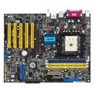
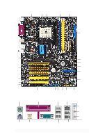
1.4.2 Core specifications 1 ATX 12V connector. This power connector connects the 4-pin 12V plug from the ATX 12V power supply. 2 North bridge controller. The VIA® K8T800 supports AGP 8X mode, Ultra V-Link, and an ultra scalable HyperTransport™ link to the CPU. 3 CPU socket. A 754-pin surface mount, Zero Insertion Force (ZIF) socket designed for the AMD® Athlon 64™processor with an integrated low-latency high-bandwidth memory controller and a highly-scalable HyperTransport™ technology-based system bus. 4 DDR DIMM sockets. These three 184-pin DIMM sockets support up to 3GB system memory using ECC or non-ECC PC3200/2700/2100/ 1600 unbuffered DDR DIMMs. 5 ATX power connector. This 20-pin connector connects to an ATX +12V power supply. The power supply must have at least 1.5A on the +5V standby lead (+5VSB). 6 IDE connectors. These dual-channel bus master IDE connectors support Ultra DMA133/100, PIO Modes 3 & 4 IDE devices. Both the primary (blue) and secondary (black) connectors are slotted to prevent incorrect insertion of the IDE ribbon cable. 7 AGP slot. This Accelerated Graphics Port (AGP) slot supports 1.5V AGP8X mode graphics cards for 3D graphical applications. 8 Floppy disk connector. This connector accommodates the provided ribbon cable for the floppy disk drive. One side of the connector is slotted to prevent incorrect insertion of the floppy disk cable. 9 SATA connectors. These four 7-pin connectors support Serial ATA that allows for up to 150MB/s data transfer rate, faster than the standard Parallel ATA with 133 MB/s. 10 RAID ATA133 connector. This bus master IDE connector supports Ultra DMA/133 IDE devices. This connector is slotted to prevent incorrect insertion of the IDE ribbon cable. 11 Flash ROM. This 4Mb firmware contains the programmable BIOS program. 12 Standby power LED. This LED lights up if there is a standby power on the motherboard. This LED acts as a reminder to turn off the system power before plugging or unplugging devices. 1-8 Chapter 1: Product introduction
-
 1
1 -
2
-
3
-
4
-
5
-
6
-
7
-
8
-
9
-
10
-
11
-
12
-
13
-
14
-
15
-
16
-
 17
17 -
 18
18 -
 19
19 -
 20
20 -
 21
21 -
 22
22 -
 23
23 -
 24
24 -
 25
25 -
 26
26 -
 27
27 -
28
-
29
-
30
-
31
-
32
-
33
-
34
-
35
-
36
-
37
-
38
-
39
-
40
-
41
-
42
-
43
-
44
-
45
-
46
-
47
-
48
-
49
-
50
-
51
-
52
-
53
-
54
-
55
-
56
-
57
-
58
-
59
-
60
-
61
-
62
-
63
-
64
-
65
-
66
-
67
-
68
-
69
-
70
-
71
-
72
-
73
-
74
-
75
-
76
-
77
-
78
-
79
-
80
-
81
-
82
-
83
-
84
-
85
-
86
-
87
-
88
-
89
-
90
-
91
-
92
-
93
-
94
-
95
-
96
-
97
-
98
-
99
-
100
-
101
-
102
-
103
-
104
-
105
-
106
-
107
-
108
-
109
-
110
-
111
-
112
-
113
-
114
-
115
-
116
-
117
-
118
-
119
-
120
-
121
-
122
-
123
-
124
-
125
-
126
-
127
-
128
-
129
-
130
-
131
-
132
-
133
-
134
-
135
-
136
-
137
-
138
-
139
-
140
-
141
-
142
-
143
-
144
 |
 |
