Asus M2A VM M2A-VM Premium user's manual - Page 41

USB connectors 10-1 pin USB56, USB78, USB910, Optical drive audio in connector 4-pin CD - front panel
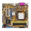
Page 41 highlights

7. USB connectors (10-1 pin USB56, USB78, USB910) These connectors are for USB 2.0 ports. Connect the USB module cable to any of these connectors, then install the module to a slot opening at the back of the system chassis. These USB connectors comply with USB 2.0 specification that supports up to 480 Mbps connection speed. USB56 USB78 USB910 USB+5V USB_P10USB_P10+ GND NC USB+5V USB_P8USB_P8+ GND NC USB+5V USB_P6USB_P6+ GND NC M2A-VM ® PIN1 PIN1 PIN1 USB+5V USB_P9USB_P9+ GND USB+5V USB_P7USB_P7+ GND USB+5V USB_P5USB_P5+ GND M2A-VM.USB.2.0.connectors Never connect a 1394 cable to the USB connectors. Doing so will damage the motherboard! The USB 2.0 module is purchased separately. 8. Optical drive audio in connector (4-pin CD) These connectors allow you to receive stereo audio input from sound sources such as a CD-ROM, TV tuner, or MPEG card. CD (black) Left Audio Channel Ground Ground Right Audio Channel M2A-VM ® M2A-VM Internal audio connector To activate ASUS Music Alarm: • Connect the analog audio cable from the optical drive to the 4-pin CD-IN connector labeled CD on the motherboard. • Connect speakers or a headphone to the Line-Out (lime-colored) port on the front or rear panel for audio output. You may also connect speakers or a headphone to the output jack on the optical drive. ASUS M2A-VM 1-29

  • 1
  • 2
  • 3
  • 4
  • 5
  • 6
  • 7
  • 8
  • 9
  • 10
  • 11
  • 12
  • 13
  • 14
  • 15
  • 16
  • 17
  • 18
  • 19
  • 20
  • 21
  • 22
  • 23
  • 24
  • 25
  • 26
  • 27
  • 28
  • 29
  • 30
  • 31
  • 32
  • 33
  • 34
  • 35
  • 36
  • 37
  • 38
  • 39
  • 40
  • 41
  • 42
  • 43
  • 44
  • 45
  • 46
  • 47
  • 48
  • 49
  • 50
  • 51
  • 52
  • 53
  • 54
  • 55
  • 56
  • 57
  • 58
  • 59
  • 60
  • 61
  • 62
  • 63
  • 64
  • 65
  • 66
  • 67
  • 68
  • 69
  • 70
  • 71
  • 72
  • 73
  • 74
  • 75
  • 76
  • 77
  • 78
  • 79
  • 80
  • 81
  • 82
  • 83
  • 84
  • 85
  • 86
  • 87
  • 88
  • 89
  • 90
  • 91
  • 92

ASUS M2A-VM
1-29
Never connect a 1394 cable to the USB connectors. Doing so will damage the
motherboard!
7.
USB connectors (10-1 pin USB56, USB78, USB910)
These connectors are for USB 2.0 ports. Connect the USB module cable
to any of these connectors, then install the module to a slot opening at the
back of the system chassis. These USB connectors comply with USB 2.0
specification that supports up to 480 Mbps connection speed.
8.
Optical drive audio in connector (4-pin CD)
These connectors allow you to receive stereo audio input from sound sources
such as a CD-ROM, TV tuner, or MPEG card.
The USB 2.0 module is purchased separately.
To activate ASUS Music Alarm:
Connect the analog audio cable from the optical drive to the 4-pin CD-IN
connector labeled CD on the motherboard.
Connect speakers or a headphone to the Line-Out (lime-colored) port on
the front or rear panel for audio output. You may also connect speakers or a
headphone to the output jack on the optical drive.
M2A-VM
M2A-VM USB 2.0 connectors
USB56
USB+5V
USB_P6-
USB_P6+
GND
NC
USB+5V
USB_P5-
USB_P5+
GND
PIN1
USB78
USB+5V
USB_P8-
USB_P8+
GND
NC
USB+5V
USB_P7-
USB_P7+
GND
PIN1
USB910
USB+5V
USB_P10-
USB_P10+
GND
NC
USB+5V
USB_P9-
USB_P9+
GND
PIN1
M2A-VM
M2A-VM Internal audio connector
CD
(black)
Right Audio Channel
Left Audio Channel
Ground
Ground