Asus MM17DE User Manual
Asus MM17DE Manual
 |
View all Asus MM17DE manuals
Add to My Manuals
Save this manual to your list of manuals |
Asus MM17DE manual content summary:
- Asus MM17DE | User Manual - Page 1
3 TAKE CARE OF THE MONITOR 3 BEFORE YOU OPERATE THE MONITOR 4 FEATURES 4 PACKING LIST 4 INSTALLATION INSTRUCTIONS 5 ADJUSTING THE VIEWING ANGLE 7 OPERATING INSTRUCTIONS 8 GENERAL INSTRUCTIONS 8 HOW TO RECONFIGURE 9 OSD MENU TABLE 10 PLUG AND PLAY 12 TROUBLESHOOTING (FAQ 13 ERROR MESSAGE - Asus MM17DE | User Manual - Page 2
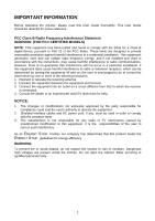
the monitor, please read this User Guide thoroughly. This User Guide should installed and used in accordance with the instructions, may cause harmful interference to radio monitor to rain or moisture. Dangerous high voltages are present inside the monitor. Do not open the cabinet. Refer servicing - Asus MM17DE | User Manual - Page 3
sold with the monitor. If you mount the monitor on a wall or shelf, use a mounting kit approved by the manufacturer and follow the kit instructions. l Slots refer all servicing to qualified service personnel. l To ensure satisfactory operation, use the monitor only with UL listed computers which have - Asus MM17DE | User Manual - Page 4
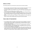
• When the screen becomes black or flashing, or cannot illuminate any more, contact your dealer or service center to replace parts. Don't repair the screen by yourself! TAKE CARE OF THE MONITOR • Do not install the monitor in a location near heat sources such as radiators or air ducts, or in a place - Asus MM17DE | User Manual - Page 5
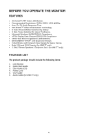
BEFORE YOU OPERATE THE MONITOR FEATURES • 43.2cm(17") TFT Color LCD Monitor. • Recommended Resolutions: SXGA MM17T only) • 1.2Wx2 Stereo Speakers / Earphone Jack. (for MM17T only) PACKAGE LIST The product package should include the following items: 1. LCD Monitor 2. Quick Start Guide 3. User Guide - Asus MM17DE | User Manual - Page 6
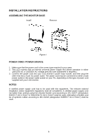
INSTRUCTIONS ASSEMBLING THE MONITOR BASE Install Remove Figure 1 POWER CORD / POWER SOURCE 1. Make sure that the power cord is the correct type required in your area. 2. This LCD monitor socket on your PC, depending on the type of power cord supplied with your LCD monitor. NOTES A certified - Asus MM17DE | User Manual - Page 7
MAKING THE CONNECTIONS Connecting the Signal Cable: Plug one end of the VGA Cableto the LCD monitor's VGA port, the other end to the computer's VGA socket and tighten the two screws on the cable connector. Moreover, for MM17T, you can buy an extra 24-Pin DVI-D cable from your dealer for the digital - Asus MM17DE | User Manual - Page 8
the full face of the monitor, then adjust the monitor's angle to your own preference. • Hold the stand so you do not topple the monitor when you change the monitor's angle. • You are able to adjust the monitor's angle from -5° to 20°. Figure 3 NOTES • Do not touch the LCD screen when you change the - Asus MM17DE | User Manual - Page 9
INSTRUCTIONS GENERAL INSTRUCTIONS Press the power button to turn the LCD monitor from the LCD monitor to your computer. • Press the power button to turn on the LCD monitor. The Power LED Indicator: • Switch the LCD monitor on or off. • LED lights blue(MM17T)/green(MM17D): normal operation mode. • - Asus MM17DE | User Manual - Page 10
• Activate Brightness adjustment menu. • Increase the level of the function selected or move to the next function as the OSD menu is activated. 5. Menu Button : • Activate the OSD (On-Screen Display) main menu. • Enter/select the icon(function) highlighted as the OSD menu is activated. HOW TO - Asus MM17DE | User Manual - Page 11
OSD MENU TABLE The table describes the function of each OSD icon Main Menu Main Sub Sub Item Menu Menu Menu Icon Item Icon Description Scenario Scenery Mode Standard Mode Theater Mode Game Mode Night Mode RGB Advance for scenery use with SPLENDID™ Video Enhancement Advance for general Windows - Asus MM17DE | User Manual - Page 12
Auto Automatically adjust the horizontal /vertical positions, phase and clock of the image Select an input signal from analog/digital source (MM17T only) Show the resolution,H/V frequency and input port of current input timing Select the desired language Recall default setting Exit OSD - Asus MM17DE | User Manual - Page 13
protocol. The host can request EDID information over the DDC2B channel. THIS MONITOR WILL APPEAR TO BE NON-FUNCTIONAL IF THERE IS NO VIDEO INPUT SIGNAL AC. Supplied with units are intended for connection to power outlet of personal computer: Please use a cord set consisting of a minimum No. 18 AWG, - Asus MM17DE | User Manual - Page 14
TROUBLESHOOTING (FAQ) Problem & Question Power LED is not ON The Power (MM17T only). Possible Solution l Press the Power Button to check if the monitor is in the ON mode. l Check if the Power Cord is properly connected the monitor and the power outlet. l Check if the monitor and the computer are - Asus MM17DE | User Manual - Page 15
-cable is properly connected , If the connector is loose, tighten the connector's screws. 2. Check the signal-cable's connection pins for damage. OUT OF RANGE︰ Your computer has been set to unsuitable display mode ,set the computer to display mode given in the following Preset Timing Table. 14 - Asus MM17DE | User Manual - Page 16
Audio Input/ Earphone Speaker (Built-in) Tilt VESA Wall Mount Power Source Power Consumption Phys. Dimension Net Weight Environmental Conditions MM17T MM17D 17.0" (43.2cm) Horizontal : 337.92mm, Vertical : 270.34mm SXGA 1280x1024@75Hz 0.264mm 300cd/㎡ (Typ.), 400cd/㎡ (Max.) 500:1 (Typ.), 600 - Asus MM17DE | User Manual - Page 17
PRESET TIMING TABLE STANDARD Dos-mode Dos-mode VGA SVGA XGA SXGA RESOLUTION 640 × 350 720 × 400 640 × 480 640 × 480 640 × 480 640 × 480 800 × 600 800 × 600 800 × 600 800 × 600 832 × 624 1024 × 768 1024 × 768 1024 × 768 1280 × 1024 1280 × 1024 HORIZONTAL FREQUENCY 31.47kHz 31.47kHz 31.47kHz 35. - Asus MM17DE | User Manual - Page 18
14. V-Sync 15. DDC-Serial Clock 24 - Pin Color Display Signal Cable(MM17T only) PIN NO. DESCRIPTION PI N NO. DESCRIPTION 1. TMDS Data 2- 13 for+5V) Shield 4. TMDS Data 4- 16. Hot Plug Detect 5. TMDS Data 4+ 17. TMDS Data 0- 6. DDC Clock 18. TMDS Data 0+ 7. DDC Data 19.
-
 1
1 -
 2
2 -
 3
3 -
 4
4 -
 5
5 -
 6
6 -
 7
7 -
8
-
9
-
10
-
11
-
12
-
13
-
14
-
15
-
16
-
17
-
18
 |
 |

TABLE OF CONTENTS
IMPORTANT INFORMATION --------------------------------------------------------- 1
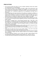
PRECAUTIONS ---------------------------------------------------------------------- 2
SPECIAL NOTES -------------------------------------------------------------------- 3
TAKE CARE OF THE MONITOR ------------------------------------------------ 3
BEFORE YOU OPERATE THE MONITOR ----------------------------------------
4
FEATURES ---------------------------------------------------------------------------- 4
PACKING LIST ----------------------------------------------------------------------- 4
INSTALLATION INSTRUCTIONS
---------------------------------------------- 5
ADJUSTING THE VIEWING ANGLE -------------------------------------------
7
OPERATING INSTRUCTIONS -------------------------------------------------------
8
GENERAL INSTRUCTIONS ------------------------------------------------------
8
HOW TO RECONFIGURE ---- --------------------------------------------------
9
OSD MENU TABLE ----------------------------------------------------------------
10
PLUG AND PLAY -------------------------------------------------------------------
12
TROUBLESHOOTING (FAQ) ---------------------------------------------------------
13
ERROR
MESSAGE & POSSIBLE
SOLUTION ----------------------------
14
APPENDIX ---------------------------------------------------------------------------------- 15
SPECIFICATIONS ------------------------------------------------------------------- 15
PRESET TIMING TABLE ---------------------------------------------------------- 16
CONNECTOR PIN ASSIGNMENT ---------------------------------------------- 17