Asus P I-P55T2P4S User Manual - Page 25
External Connectors
 |
View all Asus P I-P55T2P4S manuals
Add to My Manuals
Save this manual to your list of manuals |
Page 25 highlights
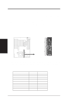
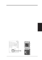
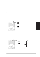
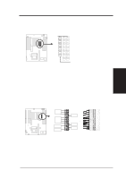
III. INSTALLATION (Connectors) III. INSTALLATION 5. External Connectors NOTE: IDE ribbon cable must be less than 18in. (46cm), with the second drive connector no more than 6in. (15cm) from the first connector. IMPORTANT: Ribbon cables should always be connected with the red stripe on the Pin 1 side of the connector. The four corners of the connectors are labeled on the motherboard. Pin 1 is the side closest to the power connector on hard drives and floppy drives. 1. Keyboard Connector (5-pin female) This connection is for a standard IBM-compatible keyboard. May also be known as a 101 enhanced keyboard. Keyboard Connector (5-pin female) Connector Plug from Keyboard 2. PS/2 Mouse Connector (6-pin block) If you are using a PS/2 mouse, you must purchase an optional PS/2 mouse set which connects to the 6 pin block and mounts to an open slot on your computer's case. You must also set "PS/2 Mouse Selection" on page 11 to enable the PS/2 Mouse. 1 234 58 1 234 58 1: GND 2: DATA 3: NC 4: VCC 5: CLK 8: NC PS/2 Mouse Module Connector P/I-P55T2P4 User's Manual 19
-
 1
1 -
2
-
3
-
4
-
5
-
6
-
7
-
8
-
9
-
10
-
11
-
12
-
13
-
14
-
15
-
16
-
17
-
18
-
19
-
 20
20 -
 21
21 -
 22
22 -
 23
23 -
 24
24 -
 25
25 -
 26
26 -
 27
27 -
 28
28 -
 29
29 -
 30
30 -
31
-
32
-
33
-
34
-
35
-
36
-
37
-
38
-
39
-
40
-
41
-
42
-
43
-
44
-
45
-
46
-
47
-
48
-
49
-
50
-
51
-
52
-
53
-
54
-
55
-
56
-
57
-
58
-
59
-
60
 |
 |
