Asus P4-P5G41 User Manual - Page 37
P5Q8L ATX Power Connectors
 |
View all Asus P4-P5G41 manuals
Add to My Manuals
Save this manual to your list of manuals |
Page 37 highlights
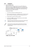
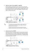
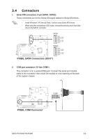
5. LED connector (6-1 pin LED_CON) This connector supports the Power and HDD activity LEDs in the system front panel. LED_CON PLED+ HD_LED+ PLED_ PLED# P5Q8L PIN 1 P5Q8L LED Connector 6. ATX power connectors (24-pin EATXPWR, 4-pin ATX12V) These connectors are for ATX power supply plugs. The plugs from the power supply are designed to fit these connectors in only one orientation. Find the proper orientation and push down firmly until the connectors completely fit. EATXPWR PIN 1 +3 Volts +3 Volts GND +5 Volts GND +5 Volts GND Power OK +5V Standby +12 Volts +12 Volts +3 Volts ATX12V +12V DC +12V DC PIN 1 GND GND +3 Volts -12 Volts GND PSON# GND GND GND -5 Volts +5 Volts +5 Volts +5 Volts GND P5Q8L P5Q8L ATX Power Connectors • DO NOT forget to connect the 4-pin ATX +12 V power plug; otherwise, the system will not boot. • We recommend that you use a PSU with a higher power output when configuring a system with more power-consuming devices. The system may become unstable or may not boot up if the power is inadequate. • Ensure that your power supply unit (PSU) can provide at least the minimum power required by your system. ASUS P2-P5G41/P4-P5G41 3-7
-
 1
1 -
2
-
3
-
4
-
5
-
6
-
7
-
8
-
9
-
10
-
11
-
12
-
13
-
14
-
15
-
16
-
17
-
18
-
19
-
20
-
21
-
22
-
23
-
24
-
25
-
26
-
27
-
28
-
29
-
30
-
31
-
 32
32 -
 33
33 -
 34
34 -
 35
35 -
 36
36 -
 37
37 -
 38
38 -
 39
39 -
 40
40 -
 41
41 -
 42
42 -
43
-
44
-
45
-
46
-
47
-
48
-
49
-
50
-
51
-
52
-
53
-
54
-
55
-
56
-
57
-
58
-
59
-
60
-
61
-
62
-
63
-
64
-
65
-
66
-
67
-
68
-
69
-
70
-
71
-
72
-
73
-
74
-
75
 |
 |
