Asus P4B-E P4B-E User Manual - Page 50
Hardware information, RAID ATA/100/66/33 connectors 40-1 pin RAID_IDE1, RAID_IDE2
 |
View all Asus P4B-E manuals
Add to My Manuals
Save this manual to your list of manuals |
Page 50 highlights
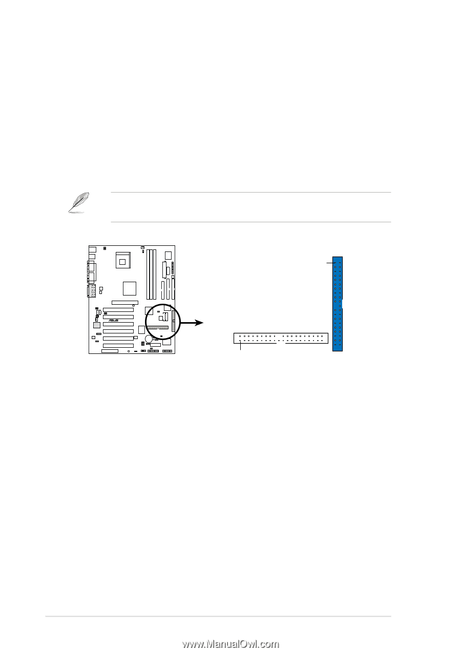
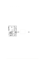
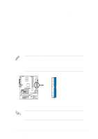
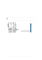
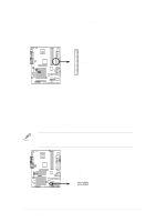
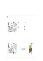
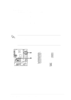
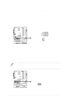
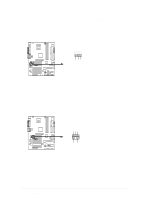
3. RAID ATA/100/66/33 connectors (40-1 pin RAID_IDE1, RAID_IDE2) These connectors support either RAID 0 or RAID 1 configuration through the onboard RAID controller chip. You can use the RAID feature to set up a disk array configuration and to support additional IDE devices. You can install a total of four hard disks, two on each connector. However, only two can function in a RAID. For a high performance RAID 0 or RAID 1 configuration, always use two separate ribbon cables, one for the primary RAID IDE connector and another for the secondary RAID IDE connector. Use the RAID software in the support CD that came with the motherboard to use the RAID feature. RAID_IDE1 Connector P4B-E ® PIN 1 NOTE: Orient the red markings (usually zigzag) on the IDE ribbon cable to PIN 1. RAID_IDE2 Connector PIN 1 P4B-E RAID IDE Connectors Figure 2-37 RAID Connectors 2-28 Chapter 2: Hardware information
-
 1
1 -
2
-
3
-
4
-
5
-
6
-
7
-
8
-
9
-
10
-
11
-
12
-
13
-
14
-
15
-
16
-
17
-
18
-
19
-
20
-
21
-
22
-
23
-
24
-
25
-
26
-
27
-
28
-
29
-
30
-
31
-
32
-
33
-
34
-
35
-
36
-
37
-
38
-
39
-
40
-
41
-
42
-
43
-
44
-
 45
45 -
 46
46 -
 47
47 -
 48
48 -
 49
49 -
 50
50 -
 51
51 -
 52
52 -
 53
53 -
 54
54 -
 55
55 -
56
-
57
-
58
-
59
-
60
-
61
-
62
-
63
-
64
-
65
-
66
-
67
-
68
-
69
-
70
-
71
-
72
-
73
-
74
-
75
-
76
-
77
-
78
-
79
-
80
-
81
-
82
-
83
-
84
-
85
-
86
-
87
-
88
-
89
-
90
-
91
-
92
-
93
-
94
-
95
-
96
-
97
-
98
-
99
-
100
-
101
-
102
-
103
-
104
-
105
-
106
-
107
-
108
-
109
-
110
-
111
-
112
-
113
-
114
-
115
-
116
-
117
-
118
-
119
-
120
-
121
-
122
-
123
-
124
-
125
-
126
-
127
-
128
 |
 |