Asus P4P800-E DELUXE P4P800-E Deluxe User's manual for English Version E1867 - Page 56
Hardware information, Front panel audio connector 10-1 pin FP_AUDIO, GAME/MIDI connector
 |
View all Asus P4P800-E DELUXE manuals
Add to My Manuals
Save this manual to your list of manuals |
Page 56 highlights
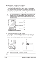
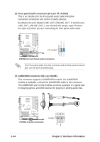
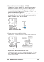
12. Front panel audio connector (10-1 pin FP_AUDIO) This is an interface for the front panel audio cable that allow convenient connection and control of audio devices. By default, the pins labeled LINE_OUT_R/BLINE_OUT_R and the pins LINE_OUT_L/BLINE_OUT_L are shorted with jumper caps. Remove the caps only when you are connecting the front panel audio cable. AGND +5VA BLINE_OUT_R BLINE_OUT_L ® P4P800-E FP_AUDIO MIC2 MICPWR Line out_R NC Line out_L P4P800-E Front Panel Audio Connector The Front panel audio Line-Out connector and the Rear panel Line-Out jack can not work simultaneously. 13. GAME/MIDI connector (16-1 pin GAME) This connector supports a GAME/MIDI module. If a GAME/MIDI module is available, connect the GAME/MIDI cable to this connector. The GAME/MIDI port on the module connects a joystick or a game pad for playing games, and MIDI devices for playing or editing audio files. +5V J1B2 J1CY GND GND J1CX J1B1 +5V ® P4P800-E P4P800-E Game Connector GAME MIDI_IN J2B2 J2CY MIDI_OUT J2CX J2B1 +5V 2-34 Chapter 2: Hardware information
-
 1
1 -
2
-
3
-
4
-
5
-
6
-
7
-
8
-
9
-
10
-
11
-
12
-
13
-
14
-
15
-
16
-
17
-
18
-
19
-
20
-
21
-
22
-
23
-
24
-
25
-
26
-
27
-
28
-
29
-
30
-
31
-
32
-
33
-
34
-
35
-
36
-
37
-
38
-
39
-
40
-
41
-
42
-
43
-
44
-
45
-
46
-
47
-
48
-
49
-
50
-
 51
51 -
 52
52 -
 53
53 -
 54
54 -
 55
55 -
 56
56 -
 57
57 -
 58
58 -
 59
59 -
 60
60 -
 61
61 -
62
-
63
-
64
-
65
-
66
-
67
-
68
-
69
-
70
-
71
-
72
-
73
-
74
-
75
-
76
-
77
-
78
-
79
-
80
-
81
-
82
-
83
-
84
-
85
-
86
-
87
-
88
-
89
-
90
-
91
-
92
-
93
-
94
-
95
-
96
-
97
-
98
-
99
-
100
-
101
-
102
-
103
-
104
-
105
-
106
-
107
-
108
-
109
-
110
-
111
-
112
-
113
-
114
-
115
-
116
-
117
-
118
-
119
-
120
-
121
-
122
-
123
-
124
-
125
-
126
-
127
-
128
-
129
-
130
-
131
-
132
-
133
-
134
-
135
-
136
-
137
-
138
-
139
-
140
-
141
-
142
-
143
 |
 |
