Asus P4SD User Guide
Asus P4SD - 865GV Socket 478 mATX Motherboard Manual
 |
UPC - 683728151935
View all Asus P4SD manuals
Add to My Manuals
Save this manual to your list of manuals |
Asus P4SD manual content summary:
- Asus P4SD | User Guide - Page 1
Motherboard P4SD-LA ( Oxford ) User Guide - Asus P4SD | User Guide - Page 2
Checklist Contents P4SD-LA specifications summary iii 1. Motherboard layout 1 2. Central Processing Unit (CPU 2 3. System memory 3 Memory configurations 3 Installing a DIMM 4 4. Expansion slots 5 Standard interrupt assignments 5 IRQ assignments for this motherboard 5 PCI slots 6 AGP slot - Asus P4SD | User Guide - Page 3
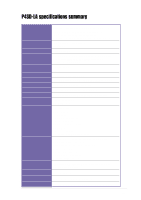
P4SD-LA specifications summary CPU Chipset Front Side Bus (FSB) Memory Expansion slots VGA Serial ATA IDE Audio LAN Special features Rear panel I/O Internal I/O BIOS features Industry standard Manageability Form factor Socket 478 for Intel® Pentium® 4 Northwood/Prescott On-die 512KB/256KB L2 cache - Asus P4SD | User Guide - Page 4
iv - Asus P4SD | User Guide - Page 5
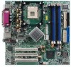
PCI 1 FRONT MICIN SPDI/F PCI 2 Audio Codec PCI 3 CD_IN AUX SPEAKER OUT FRONT HP-OUT 1394 TI43AB22A 1394 PHY 01 23 BATTERY1 Intel ICH5 Chipset P31 P30 J19 4Mb BIOS USB2 USB1 HPANEL ATX Power Connector 24.5cm (9.64in) SECONDARY IDE PRIMARY IDE ASUS P4SD-LA motherboard 1 - Asus P4SD | User Guide - Page 6
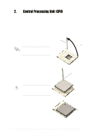
socket lever to secure the CPU. The lever clicks on the side tab to indicate that it is locked. 6. Install a CPU heatsink and fan following the instructions that came with the heatsink package. 7. Connect the CPU fan cable to the CPU_FAN1 connector on the motherboard. 2 ASUS P4SD-LA motherboard - Asus P4SD | User Guide - Page 7
only identical (the same type and size) DDR DIMM pairs using the recommended configurations. 3. Make sure that the memory frequency matches the CPU FSB (Front Side Bus). Refer to Table 2 below. 4. Double-sided 16-bit DDR DIMMs are not supported on this motherboard. ASUS P4SD-LA motherboard 3 - Asus P4SD | User Guide - Page 8
outward. DDR DIMM notch 2. Align a DIMM on the socket such that the notch on the DIMM matches the break on the socket. 3. Firmly insert the DIMM into the socket until the retaining clips snap back in place and the DIMM is properly seated. Unlocked Retaining Clip 4 ASUS P4SD-LA motherboard - Asus P4SD | User Guide - Page 9
Advance AC'97 CODEC 11* 6 Standard PCI Graphics Adapter (VGA) 12* 7 PS/2 Compatible Mouse Port 13 8 Numeric Data Processor 14* controller shared Onboard LAN - - - shared - - - - Onboard audio - used - - - - - - Onboard 1394 controller - - - - - shared - - ASUS P4SD-LA motherboard 5 - Asus P4SD | User Guide - Page 10
+0.8V+1.5V specification. Note the notches on the card golden fingers to ensure that they fit the AGP slot on your motherboard. Install only +0.8V/+1.5V AGP cards on this motherboard! AGP Card without Retention Notch P4SD-LA Accelerated Graphics Port (AGP8X) P4SD-LA 6 ASUS P4SD-LA motherboard - Asus P4SD | User Guide - Page 11
the boot process and enter BIOS setup to re-enter data. Except when clearing the RTC RAM, never remove the cap on jumper J19 default position. Removing the cap will cause system boot failure! P4SD-LA P4SD-LA Clear RTC RAM J19 3 2 1 Clear CMOS 3 2 1 Normal (Default) ASUS P4SD-LA motherboard 7 - Asus P4SD | User Guide - Page 12
powering up if the power supply is inadequate. ATX12V1 ATXPWR1 P4SD-LA GND +12V DC P4SD-LA ATX Power Connector GND +12.0VDC +12V DC +5VSB PWR_OK COM +5.0VDC COM +5.0VDC COM +3.3VDC +3.3VDC +5.0VDC +5.0VDC -5.0VDC COM COM COM PS_ON# COM -12.0VDC +3.3VDC 8 ASUS P4SD-LA motherboard - Asus P4SD | User Guide - Page 13
its jumper accordingly. Refer to the hard disk documentation for the jumper settings. BIOS supports specific device bootup. If you have more than two UltraDMA/100/66 devices IDE ribbon cable to PIN 1. P4SD-LA SECONDARY IDE PRIMARY IDE P4SD-LA IDE Connectors PIN 1 PIN 1 ASUS P4SD-LA motherboard 9 - Asus P4SD | User Guide - Page 14
plug to this connector, and the 6-pin cable plug to the 1394 module. You may also connect a 1394-compliant internal hard disk to this connector. P4SD-LA TPAGND TPB+12V GND 1394 1 P4SD-LA IEEE-1394 Connectors TPA+ GND TPB+ +12V 10 ASUS P4SD-LA motherboard - Asus P4SD | User Guide - Page 15
with USB 2.0 specification that supports up to 480 Mbps audio module. Connect one end of the audio cable to this connector and the other end to the audio module. SPEAKER OUT 1 P4SD-LA Speaker Out Connector P4SD-LA +12V Speak Out-R signal Ground Speak Out-L signal ASUS P4SD-LA motherboard - Asus P4SD | User Guide - Page 16
9. Microphone connector (3-pin FRONT MICIN) This connector is for a chassis-mounted front panel microphone jack. Use a 3-pin audio cable to connect the microphone jack to this connector. FRONT MICIN MIC Power MIC Input Ground P4SD-LA ront Microphone Connector P4SD-LA 12 ASUS P4SD-LA motherboard - Asus P4SD | User Guide - Page 17
SPDI/F) This connector is for an S/PDIF audio module that allows digital instead of analog sound output. Connect one end of the audio cable to this connector and the other end to the S/PDIF module. P4SD-LA P4SD-LA Digital Audio Interface SPDI/F +5V SPDIFOUT Ground ASUS P4SD-LA motherboard 13 - Asus P4SD | User Guide - Page 18
on the BIOS or OS settings. Pressing the power switch while in the ON mode for more than 4 seconds turns the system OFF. • Reset Switch Lead (2-pin RESET) This 2-pin connector connects to the case-mounted reset switch for rebooting the system without turning off the system power. 14 ASUS P4SD-LA
-
 1
1 -
 2
2 -
 3
3 -
 4
4 -
 5
5 -
 6
6 -
 7
7 -
8
-
9
-
10
-
11
-
12
-
13
-
14
-
15
-
16
-
17
-
18
 |
 |

Motherboard
P4SD-LA
( Oxford )
User Guide