Asus P4SD User Guide - Page 9
Expansion slots - driver
 |
UPC - 683728151935
View all Asus P4SD manuals
Add to My Manuals
Save this manual to your list of manuals |
Page 9 highlights
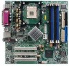
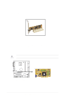
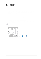
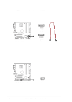
4. Expansion slots The motherboard has three PCI slots and one Accelerated Graphics Port (AGP) slot. To install and configure an expansion card: 1. Install an expansion card following the instructions that came with the chassis. NOTE: The AGP slot supports only +0.8V and +1.5V AGP cards. 2. Turn on the system and change the necessary BIOS settings, if any. See Chapter 2 for BIOS information. 3. Assign an IRQ to the card. Refer to the tables below. 4. Install the drivers and/or software applications for the expansion card according to the card documentation. Standard interrupt assignments IRQ Priority Standard Function 0 1 System Timer 1 2 Keyboard Controller 2 N/A Programmable Interrupt 3* 11 Communications Port (COM2) 4* 12 Communications Port (COM1) 5* 13 IRQ holder for PCI steering 6 14 Floppy Disk Controller 7* 15 Printer Port (LPT1) 8 3 System CMOS/Real Time Clock 9* 4 IRQ holder for PCI steering 10* 5 Advance AC'97 CODEC 11* 6 Standard PCI Graphics Adapter (VGA) 12* 7 PS/2 Compatible Mouse Port 13 8 Numeric Data Processor 14* 9 Primary IDE Channel 15* 10 Secondary IDE Channel * These IRQs are usually available for ISA or PCI devices. IRQ assignments for this motherboard A B C D E F GH PCI slot 1 - - - - - shared - - PCI slot 2 - - - - - - used - PCI slot 3 shared AGP slot shared Onboard USB controller 1 shared Onboard USB controller 2 - - - shared - - - - Onboard USB controller 3 - - used - - - - - Onboard USB controller 4 shared Onboard USB 2.0 controller shared Onboard LAN - - - shared - - - - Onboard audio - used - - - - - - Onboard 1394 controller - - - - - shared - - ASUS P4SD-LA motherboard 5
-
 1
1 -
2
-
3
-
 4
4 -
 5
5 -
 6
6 -
 7
7 -
 8
8 -
 9
9 -
 10
10 -
 11
11 -
 12
12 -
 13
13 -
 14
14 -
15
-
16
-
17
-
18
 |
 |
