Asus P4V8X-X P4V8X-X User Manual
Asus P4V8X-X Manual
 |
View all Asus P4V8X-X manuals
Add to My Manuals
Save this manual to your list of manuals |
Asus P4V8X-X manual content summary:
- Asus P4V8X-X | P4V8X-X User Manual - Page 1
Motherboard P4V8X-X User Guide - Asus P4V8X-X | P4V8X-X User Manual - Page 2
express written permission of ASUSTeK COMPUTER INC. ("ASUS"). Product warranty or service will not be extended if: (1) the ASUS HAS BEEN ADVISED OF THE POSSIBILITY OF SUCH DAMAGES ARISING FROM ANY DEFECT OR ERROR IN THIS MANUAL OR PRODUCT. SPECIFICATIONS AND INFORMATION CONTAINED IN THIS MANUAL - Asus P4V8X-X | P4V8X-X User Manual - Page 3
v Safety information vi About this guide vii ASUS contact information viii P4V8X-X specifications summary ix Chapter 1: Product introduction 1.1 Welcome 1-2 1.2 Package contents 1-2 1.3 Special features 1-2 1.4 Motherboard components 1-4 1.5 Motherboard layout 1-7 1.6 Before you proceed - Asus P4V8X-X | P4V8X-X User Manual - Page 4
2.4.2 USB Configuration 2-15 2.4.3 CPU Configuration 2-17 2.4.4 Chipset 2-17 2.4.5 Onboard Devices Configuration 2-20 2.4.6 PCI PnP 2-21 2.5 Power menu 2-22 2.5.1 2.5.2 2.5.3 2.5.4 2.5.5 2.5.6 Suspend Mode [Auto 2-22 Repost Video on S3 Resume [No 2-22 ACPI 2.0 Support [No 2-22 ACPI APIC - Asus P4V8X-X | P4V8X-X User Manual - Page 5
. This equipment generates, uses and can radiate radio frequency energy and, if not installed and used in accordance with manufacturer's instructions, may cause harmful interference to radio communications. However, there is no guarantee that interference will not occur in a particular installation - Asus P4V8X-X | P4V8X-X User Manual - Page 6
supply is broken, do not try to fix it by yourself. Contact a qualified service technician or your retailer. Operation safety • Before installing the motherboard and adding devices on it, carefully read all the manuals that came with the package. • Before using the product, make sure all cables - Asus P4V8X-X | P4V8X-X User Manual - Page 7
this guide To make sure that you perform certain tasks properly, take note of the following symbols used throughout this manual. WARNING updates. 1. ASUS Websites The ASUS websites worldwide provide updated information on ASUS hardware and software products. The ASUS websites are listed in the ASUS - Asus P4V8X-X | P4V8X-X User Manual - Page 8
, CA 94538, USA Fax +1-510-608-4555 E-mail [email protected] Web site usa.asus.com Technical Support Telephone (General) (Notebook) Support fax Support e-mail +1-502-995-0883 +1-510-739-3777 +1-502-933-8713 [email protected] ASUS COMPUTER GmbH (Germany and Austria) Address Harkort Str. 25, D-40880 - Asus P4V8X-X | P4V8X-X User Manual - Page 9
P4V8X-X specifications summary CPU Chipset Front Side Bus (FSB) Memory Expansion slots Storage Audio LAN USB AI Overclocking Special features Back panel I/O Socket 478 for Intel® Pentium® 4 / Celeron with speeds up to 3.2 GHz+ Supports Intel® Hyper-Threading technology Supports Intel® Prescott - Asus P4V8X-X | P4V8X-X User Manual - Page 10
P4V8X-X specifications summary Internal I/O BIOS features Industry standard Manageability Power Requirement Support CD contents Form Factor 2 x USB 2.0 connector for 4 additional USB ports CPU/Chassis fan connectors 20-pin/4-pin ATX 12V power connectors CD/AUX connectors Game/MIDI connector 10-1 - Asus P4V8X-X | P4V8X-X User Manual - Page 11
Chapter 1 This chapter describes the features of the P4V8X-X motherboard. It includes brief descriptions of the motherboard components, and illustrations of the layout, jumper settings, and connectors. Product introduction - Asus P4V8X-X | P4V8X-X User Manual - Page 12
it another standout in the long line of ASUS quality motherboards! The P4V8X-X incorporates the Intel® Pentium® 4 / Celeron processors in 478-pin package coupled with the VIA® P4X533 chipset to set a new benchmark for an effective desktop platform solution. Supporting up to 3GB of system memory with - Asus P4V8X-X | P4V8X-X User Manual - Page 13
function to provide efficient power management for advanced operating systems. CrashFree BIOS 2 CrashFree BIOS 2 allows users to restore BIOS data from a floppy diskette or recovery CD when BIOS code and data are corrupted during upgrade or when invaded by a virus. ASUS motherboards now enable users - Asus P4V8X-X | P4V8X-X User Manual - Page 14
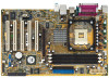
components Before you install the motherboard, learn about its major components and available features to facilitate the installation and future upgrades. Refer to the succeeding pages for the component descriptions. 1 23 4 5 6 7 - Asus P4V8X-X | P4V8X-X User Manual - Page 15
connector connects the 4-pin 12V plug from the ATX 12V power supply. 2 CPU socket. A 478-pin surface mount, Zero Insertion Force (ZIF) socket for the Intel® Pentium® 4 or Celeron® processors, with 800*/533/400 MHz system bus that allows 6.4GB/s, 4.3GB/s, and 3.2GB/s data transfer rates, respectively - Asus P4V8X-X | P4V8X-X User Manual - Page 16
slots support bus master PCI cards like SCSI or LAN cards with 133MB/s maximum throughput. 16 LAN controller. This Realtek RTL8201BL LAN PHY supports 10BASE jacks change when you select the 6-channel audio configuration as shown in the following table: Audio 2, 4 or 6-channel configuration Light - Asus P4V8X-X | P4V8X-X User Manual - Page 17
CD AUX Audio Codec Super I/O 4Mbit ROM Accelerated Graphics Port (AGP) SATA1 PCI1 ® PCI2 P4V8X-X PCI3 PCI4 SB_PWR1 PCI5 GAME1 VIA VT8237 Chipset SATA2 CR2032 3V Lithium Cell CMOS Power CHASSIS1 CLRTC1 USBPW78 USBPW56 USB78 USB56 CHA_FAN1 PANEL1 FLOPPY ASUS P4V8X-X motherboard 1-7 - Asus P4V8X-X | P4V8X-X User Manual - Page 18
system and unplug the power cable before removing or plugging in any motherboard component. ® P4V8X-X P4V8X-X Onboard LED SB_PWR1 ON Standby Power OFF Powered Off Install only 0.8V and 1.5V AGP cards on this motherboard to prevent damage to your AGP card or motherboard. 1-8 Chapter 1: Product - Asus P4V8X-X | P4V8X-X User Manual - Page 19
as indicated in the image below. 1.7.2 Screw holes Place seven (7) screws into the holes indicated by circles to secure the motherboard to the chassis. Do not overtighten the screws! Doing so may damage the motherboard. Place this side towards the rear of the chassis ASUS P4V8X-X motherboard 1-9 - Asus P4V8X-X | P4V8X-X User Manual - Page 20
one corner. This mark indicates the processor Pin 1 that should match a specific corner of the CPU socket. ® P4V8X-X P4V8X-X Socket 478 Gold Arrow • If the system becomes unstable when overclocking with an 800MHz FSB CPU, enable the CPU Compatible Mode item in the BIOS to lower FSB frequency. See - Asus P4V8X-X | P4V8X-X User Manual - Page 21
the socket lever to secure the CPU. The lever clicks on the side tab to indicate that it is locked. 6. Install a CPU heatsink and fan following the instructions that came with the heatsink package. 7. Connect the CPU fan cable to the CPU_FAN1 connector on the motherboard. ASUS P4V8X-X motherboard - Asus P4V8X-X | P4V8X-X User Manual - Page 22
DIMM3 104 Pins 80 Pins ® P4V8X-X P4V8X-X 184-Pin DDR DIMM Sockets 1.9.1 Installing a DIMM Make sure to unplug the power supply before adding or removing DIMMs or other system components. Failure to do so may cause severe damage to both the motherboard and the components. Follow these steps - Asus P4V8X-X | P4V8X-X User Manual - Page 23
, 256MB, 512MB, and 1GB DDR DIMMs into the DIMM sockets on this motherboard. PC3200 DDR DIMMs max to 2 DIMMs only. Table 1 DDR400 Qualified Vendor List from ASUS qualified vendors for better system performance. Visit the ASUS website (www.asus.com) for the latest QVL. ASUS P4V8X-X motherboard - Asus P4V8X-X | P4V8X-X User Manual - Page 24
the instructions that came with the chassis. NOTE: The AGP slot supports only 1.5V and 0.8V AGP cards. 2. Turn on the system and change the necessary BIOS settings, if any. See Chapter 2 for BIOS information. 3. Assign an IRQ to the card. Refer to the tables below. 4. Install the drivers and - Asus P4V8X-X | P4V8X-X User Manual - Page 25
ask for one with +1.5V or +0.8V specification. Note the notches on the card golden fingers to ensure that they fit the AGP slot on your motherboard. This motherboard does not support 3.3V AGP cards. ® P4V8X-X Keyed for 1.5v P4V8X-X Accelerated Graphics Port (AGP) ASUS P4V8X-X motherboard 1-15 - Asus P4V8X-X | P4V8X-X User Manual - Page 26
power cord and turn ON the computer. 4. Hold down the key during the boot process and enter BIOS setup to re-enter data. Except when clearing the RTC RAM, never remove the cap on CLRTC1 jumper default position. Removing the cap will cause system boot failure! ® P4V8X-X P4V8X-X Clear RTC RAM - Asus P4V8X-X | P4V8X-X User Manual - Page 27
USB port. 2. The total current consumed must NOT exceed the power supply capability (+5VSB) whether under normal or in sleep mode. USBPW12 USBPW34 12 23 +5V (Default) +5VSB ® P4V8X-X USBPW78 USBPW56 12 23 +5V P4V8X-X USB Device Wake Up (Default) +5VSB ASUS P4V8X-X motherboard 1-17 - Asus P4V8X-X | P4V8X-X User Manual - Page 28
34-1 pin FLOPPY1) This connector supports the provided floppy drive ribbon cable. After connecting one end to the motherboard, connect the other end to the floppy drive. (Pin 5 is removed to prevent incorrect insertion when using ribbon cables with pin 5 plug). ® P4V8X-X PIN 1 FLOPPY1 NOTE: Orient - Asus P4V8X-X | P4V8X-X User Manual - Page 29
to the hard disk documentation for the jumper settings. BIOS supports specific device bootup. If you have more than two UltraDMA100/66 P4V8X-X P4V8X-X IDE Connectors SEC_IDE1 PRI_IDE1 NOTE: Orient the red markings (usually zigzag) on the IDE ribbon cable to PIN 1. PIN 1 ASUS P4V8X-X motherboard - Asus P4V8X-X | P4V8X-X User Manual - Page 30
GND +12V DC P4V8X-X ATX Power Connectors 5. CPU and chassis fan connectors (3-pin CPU_FAN1, CHA_FAN1) The fan connectors support cooling fans of 350mA~740mA (8.88W max.) or a total of 1A~2.22A (26.64W max.) at +12V. Connect the fan cables to the fan connectors on the motherboard, making sure that - Asus P4V8X-X | P4V8X-X User Manual - Page 31
Channel Ground Ground Left Audio Channel P4V8X-X Internal Audio Connectors 7. USB header (10-1 pin USB56, USB78) If the USB ports on the rear panel are inadequate, two USB headers are available for additional USB ports. The USB header complies with USB 2.0 specification that supports up to 480 - Asus P4V8X-X | P4V8X-X User Manual - Page 32
on the module connects a joystick or a game pad for playing games, and MIDI devices for playing or editing audio files. The USB/GAME module is purchased separately. +5V J1B2 J1CY GND GND J1CX J1B1 +5V ® P4V8X-X P4V8X-X Game Connector GAME1 MIDI_IN J2B2 J2CY MIDI_OUT J2CX J2B1 +5V 9. Front panel - Asus P4V8X-X | P4V8X-X User Manual - Page 33
system power LED. The LED lights up when you turn on the system power, and blinks when the system is in sleep mode. • System Warning Speaker Lead (4-pin SPKR) This 4-pin connector connects to the case-mounted speaker and allows you to hear system beeps and warnings. ASUS P4V8X-X motherboard 1-23 - Asus P4V8X-X | P4V8X-X User Manual - Page 34
and SLEEP, or ON and SOFT OFF, depending on the BIOS or OS settings. Pressing the power switch while in the ON mode for more than 4 seconds turns the system OFF. • System Management Interrupt Lead (2-pin SMI) This 2-pin connector allows you to manually place the system into a suspend mode, or "green - Asus P4V8X-X | P4V8X-X User Manual - Page 35
Chapter 2 This chapter tells how to change system settings through the BIOS Setup menus. Detailed descriptions of the BIOS parameters are also provided. BIOS information - Asus P4V8X-X | P4V8X-X User Manual - Page 36
screen instructions to complete the process. 2. Copy the original (or the latest) motherboard BIOS to the bootable floppy disk. 2.1.2 Using AFUDOS to update the BIOS Update the BIOS using the AFUDOS.EXE utility in DOS environment. 1. Visit the ASUS website (www.asus.com) to download the latest BIOS - Asus P4V8X-X | P4V8X-X User Manual - Page 37
.rom AMI Firmware Update Utility - Version 1.10 Copyright (C) 2002 American Megatrends, Inc. All rights reserved. Reading file ..... done Erasing flash .... done Writing flash .... 0x0008CC00 (9%) Verifying flash .. done A:\> 5. Reboot the system from the hard disk. ASUS P4V8X-X motherboard 2-3 - Asus P4V8X-X | P4V8X-X User Manual - Page 38
space (at least 600KB) to store the file. A:\>afudos /oMYBIOS03.rom AMI Firmware Update Utility - Version 1.10 Copyright (C) 2002 American Megatrends, Inc. All rights reserved. Reading flash ..... done A:\> When the BIOS copy process is complete, the utility returns to the DOS prompt. 2-4 Chapter - Asus P4V8X-X | P4V8X-X User Manual - Page 39
by simply pressing + during the Power-On Self Tests (POST). To update the BIOS using ASUS EZ Flash: 1. Visit the ASUS website (www.asus.com) to download the latest BIOS file for your motherboard and rename it to P4V8XX.ROM. Save the BIOS file to a floppy disk. 2. Reboot the system - Asus P4V8X-X | P4V8X-X User Manual - Page 40
a floppy disk that contains the original, or the latest, BIOS file for this motherboard (P4V8XX.ROM). If the BIOS file that you downloaded from the ASUS website has a different filename (e.g. P4V8XX2.ROM), rename it to P4V8XX.ROM. The BIOS update process continues when the P4V8XX.ROM is found. Bad - Asus P4V8X-X | P4V8X-X User Manual - Page 41
updating the BIOS! Doing so may cause system boot failure! 4. When the BIOS update process is complete, reboot the system. The recovered BIOS may not be the latest BIOS version for this motherboard. Visit the ASUS website (www.asus.com) to download the latest BIOS file. ASUS P4V8X-X motherboard - Asus P4V8X-X | P4V8X-X User Manual - Page 42
Setup program This motherboard supports a programmable firmware hub (FWH) that you can update using the provided utility described in section "2.1 Managing and updating your BIOS." Use the BIOS Setup program when you are installing a motherboard, reconfiguring your system, or prompted to "Run Setup - Asus P4V8X-X | P4V8X-X User Manual - Page 43
the basic system configuration For changing the advanced system settings For changing the advanced power management (APM) configuration For changing the system boot configuration For selecting the exit Some of the navigation keys differ from one screen to another. ASUS P4V8X-X motherboard 2-9 - Asus P4V8X-X | P4V8X-X User Manual - Page 44
displays the specific items for ] :[ASUS CD-S340] :[Not Detected] :[Not Detected] The other items (Advanced, Power, Boot [Available] [Available] NO: Lets the bIOS configure all the devices in the system. YES and Exit ESC Exit Pop-up window Scroll bar 2.2.9 General help At the top right corner - Asus P4V8X-X | P4V8X-X User Manual - Page 45
screen appears giving you an overview of the basic system information. Refer to section "2.2.1 BIOS menu screen" for information on the menu screen items and how to navigate through [360K, 5.25 in.] [1.2M , 5.25 in.] [720K , 3.5 in.] [1.44M, 3.5 in.] [2.88M, 3.5 in.] ASUS P4V8X-X motherboard 2-11 - Asus P4V8X-X | P4V8X-X User Manual - Page 46
Setup, BIOS auto-detects the presence of IDE devices. There is a separate sub-menu for each IDE device. Select a device item then press Enter to display the IDE device information. Primary IDE Master Device : Hard Disk Vendor : ST320413A Size : 20.0GB LBA Mode : Supported Block Mode - Asus P4V8X-X | P4V8X-X User Manual - Page 47
Select Item +- Change Option F1 General Help F10 Save and Exit ESC Exit AMI BIOS This item displays the auto-detected BIOS information. Processor This item displays the auto-detected CPU specification. System Memory This item displays the auto-detected system memory. ASUS P4V8X-X motherboard 2-13 - Asus P4V8X-X | P4V8X-X User Manual - Page 48
Configuration CPU Configuration Chipset Onboard Devices Configuration PCI PnP Configure CPU. ESC Exit CPU Compatible Mode [Disabled] This item allows you to enable or disable the CPU compatible mode. If your system becomes unstable when overclocking with an 800MHz Front Side Bus CPU - Asus P4V8X-X | P4V8X-X User Manual - Page 49
USB 2.0 Ports Enable Legacy USB Support USB 2.0 Controller Mode [8 USB Ports] [Enabled] [Auto] [HiSpeed] USB Mass Storage Device Configuration Enables USB host controllers. Select Screen Select Item +- Change Option F1 General Help F10 Save and Exit ESC Exit ASUS P4V8X-X motherboard 2-15 - Asus P4V8X-X | P4V8X-X User Manual - Page 50
If detected, the USB controller legacy mode is enabled. If no USB device is detected, the legacy USB support is disabled. Configuration options: [Disabled] [Enabled] [Auto] USB 2.0 Controller Mode [HiSpeed] This item options: [10 Sec ] [20 Sec] [30 Sec] [40 Sec] 2-16 Chapter 2: BIOS information - Asus P4V8X-X | P4V8X-X User Manual - Page 51
you to change the advanced chipset settings. Select an item then press Enter to display the sub-menu. NorthBridge VIA P4X533 Configuration SouthBridge VIA VT8237 Configuration Select Screen Select Item +- Change Option F1 General Help F10 Save and Exit ESC Exit ASUS P4V8X-X motherboard 2-17 - Asus P4V8X-X | P4V8X-X User Manual - Page 52
Command Rate Primary Graphics Adapter V-Link 8X Supported AGP Mode Graphics Aperture Size [Enabled] [Auto] [4QW] [2T] [AGP] [Enabled] Auto [64MB] Select Screen [2T] Configuration options: [2T] [1T] Primary Graphics Adapter [AGP] Configuration options: [PCI] [AGP] 2-18 Chapter 2: BIOS information - Asus P4V8X-X | P4V8X-X User Manual - Page 53
] OnBoard LAN Boot ROM [Disabled] This item enables or disables the onboard LAN Boot ROM. Configuration options: [Disabled] [Enabled] OnBoard AC'97 Audio [Auto] This item disables or set to auto-detect the onboard AC'97 audio CODEC. Configuration options: [Disabled] [Auto] ASUS P4V8X-X motherboard - Asus P4V8X-X | P4V8X-X User Manual - Page 54
Port [Disabled] This item enable or disables the onboard Game/MIDI port. Configuration options: [Disabled] [200/300] [200/330] [208/300] [208/330] 2-20 Chapter 2: BIOS information - Asus P4V8X-X | P4V8X-X User Manual - Page 55
F1 General Help F10 Save and Exit ESC Exit Plug and Play O/S [No] When set to [No], BIOS configures all the devices in the system. When set to [Yes] and if you installed a Plug & Play to [Disabled] deactivates this feature. Configuration options: [Disabled] [Enabled] ASUS P4V8X-X motherboard 2-21 - Asus P4V8X-X | P4V8X-X User Manual - Page 56
] [Enabled] IRQ xx [Available] When set to [Available], the specific IRQ is free for use of PCI/PnP devices. When set to [Reserved], the IRQ is reserved for legacy ISA devices. Configuration options: [Available] [Reserved] 2.5 Power menu The Power menu items allow you to change the settings for the - Asus P4V8X-X | P4V8X-X User Manual - Page 57
options: [Disabled] [1 Min] [2 Min] [4 Min] [8 Min] [10 Min] [20 Min] [30 Min] [40 Min] [50 Min] [60 Min] Power Button Mode [On/Off] Allows the system to go into On/Off mode or suspend mode when the power button is pressed. Configuration options: [On/Off] [Suspend] ASUS P4V8X-X motherboard 2-23 - Asus P4V8X-X | P4V8X-X User Manual - Page 58
power on. Power On by Onboard LAN [Disabled] Allows you to enable or disable the onboard LAN to generate PME in SoftOFF mode. Configuration options: [Disabled] [Enabled] Power : [Disabled] [Enabled] Power On by PS/2 Mouse Power On by PS/2 Keyboard [Disabled] This parameter allows you to use specific - Asus P4V8X-X | P4V8X-X User Manual - Page 59
If any of the fans is not connected to the motherboard, the specific field shows N/A. CPU Reference Voltage, +3.3V Voltage, +5V Voltage, +12V found an error. Enter Power setup menu for details". You will then be prompted to "Press F1 to continue or DEL to enter SETUP". ASUS P4V8X-X motherboard 2-25 - Asus P4V8X-X | P4V8X-X User Manual - Page 60
device items that appear on the screen depends on the the number of devices installed in the system. Configuration options: [xxxxx Drive] [Disabled] 2-26 Chapter 2: BIOS information - Asus P4V8X-X | P4V8X-X User Manual - Page 61
BIOS] [Keep Current] Bootup Num-Lock [On] Allows you to select the power-on state for the NumLock. Configuration options: [Off] [On] PS/2 Mouse Support [Auto] Allows you to enable or disable support to run Setup" during POST. Configuration options: [Disabled] [Enabled] ASUS P4V8X-X motherboard 2-27 - Asus P4V8X-X | P4V8X-X User Manual - Page 62
as in setting a user password. To clear the supervisor password, select the Change Supervisor Password then press Enter. The message "Password Uninstalled" appears. 2-28 Chapter 2: BIOS information - Asus P4V8X-X | P4V8X-X User Manual - Page 63
RAM BIOS checks for user password both when accessing Setup and booting the system. Configuration options: [Setup] [Always] Boot Sector Virus Protection [Disabled] Allows you to enable or disable the boot sector virus protection. Configuration options: [Disabled] [Enabled] ASUS P4V8X-X motherboard - Asus P4V8X-X | P4V8X-X User Manual - Page 64
CMOS RAM is sustained by an onboard backup battery and stays on even when the PC is turned off. When you select this option, a confirmation window appears to fields other than system date, system time, and password, the BIOS asks for a confirmation before exiting. Discard Changes This option allows - Asus P4V8X-X | P4V8X-X User Manual - Page 65
Chapter 3 This chapter describes the contents of the support CD that comes with the motherboard package. Software support - Asus P4V8X-X | P4V8X-X User Manual - Page 66
contains useful software and several utility drivers that enhance the motherboard features. The contents of the support CD are subject to change at any time without notice. Visit the ASUS website for updates. 3.2.1 Running the support CD To begin using the support CD, simply insert the CD into - Asus P4V8X-X | P4V8X-X User Manual - Page 67
Mbps networking. USB 2.0 Driver This item installs the USB 2.0 driver. For Windows XP users, make sure to install WinXP Service Pack 1 to support USB 2.0. 3.2.3 Utilities menu The Utilities menu shows the applications and other software that the motherboard supports. ASUS P4V8X-X motherboard 3-3 - Asus P4V8X-X | P4V8X-X User Manual - Page 68
speed, CPU temperature, and system voltages, and alerts you on any detected problems. This utility helps you keep your computer at a healthy operating condition. Install ASUS Update This program allows you to download the latest version of the BIOS from the ASUS website. Before using the ASUS Update - Asus P4V8X-X | P4V8X-X User Manual - Page 69
system. When using Windows 2000 or Windows XP operating systems, make sure to copy the RAID driver from the motherboard support CD to a floppy disk before creating RAID configurations. 3.3.1 Install the Serial ATA (SATA) hard disks The VIA® VT8237 southbridge chipset supports Serial ATA hard disk - Asus P4V8X-X | P4V8X-X User Manual - Page 70
motherboard's secondary Serial ATA connector (SATA2). 5. Connect the other end of Serial ATA cable to the secondary Serial ATA hard disk. 6. Connect the Serial ATA power cable to the power connector on each drive. 7. Proceed to section 5.4.2 "Entering VIA® Tech RAID BIOS Chapter 3: Software support - Asus P4V8X-X | P4V8X-X User Manual - Page 71
to auto-configure the RAID array by selecting Auto Setup for Performance or manually configure the RAID array for stripped sets. If you want to manually configure the RAID array continue with next step list of valid array block sizes are displayed on a pop-up menu. ASUS P4V8X-X motherboard 3-7 - Asus P4V8X-X | P4V8X-X User Manual - Page 72
computer 16K systems used mainly for audio and video editing, a 32K higher to setup hard disk for RAID system. The following confirmation message RAID array by selecting Auto Setup for Data Security or manually configure the RAID array for mirrored sets. If you want to manually configure the RAID - Asus P4V8X-X | P4V8X-X User Manual - Page 73
RAID BIOS utility RAID arrays. 2. Press the key to select a RAID array to delete. The following confirmation message appears. The selected array will be destroyed. Are you sure? Continue? Press Y/N Press "Y" to confirm or "N" to return to the configuration options. ASUS P4V8X-X motherboard - Asus P4V8X-X | P4V8X-X User Manual - Page 74
RAID BIOS RAID array with the hard disk attached to VIA IDE controller F1 : View Array/Disk Status , : Move to next item Enter: Confirme the selection ESC : Exit Array Name Mode Size(GB) Status xxxxx xxx.xx Hdd xxxxx xxx.xx Hdd Serial Number: xxxxxxxx 3-10 Chapter 3: Software support
-
 1
1 -
 2
2 -
 3
3 -
 4
4 -
 5
5 -
 6
6 -
 7
7 -
8
-
9
-
10
-
11
-
12
-
13
-
14
-
15
-
16
-
17
-
18
-
19
-
20
-
21
-
22
-
23
-
24
-
25
-
26
-
27
-
28
-
29
-
30
-
31
-
32
-
33
-
34
-
35
-
36
-
37
-
38
-
39
-
40
-
41
-
42
-
43
-
44
-
45
-
46
-
47
-
48
-
49
-
50
-
51
-
52
-
53
-
54
-
55
-
56
-
57
-
58
-
59
-
60
-
61
-
62
-
63
-
64
-
65
-
66
-
67
-
68
-
69
-
70
-
71
-
72
-
73
-
74
 |
 |

Motherboard
P4V8X-X
User Guide