Asus P4XP-X User Manual - Page 26
IDE connectors 40-1 pin PRI_IDE1, SEC_IDE1, Internal audio connectors 4-pin CD1, AUX1 - bios
 |
View all Asus P4XP-X manuals
Add to My Manuals
Save this manual to your list of manuals |
Page 26 highlights
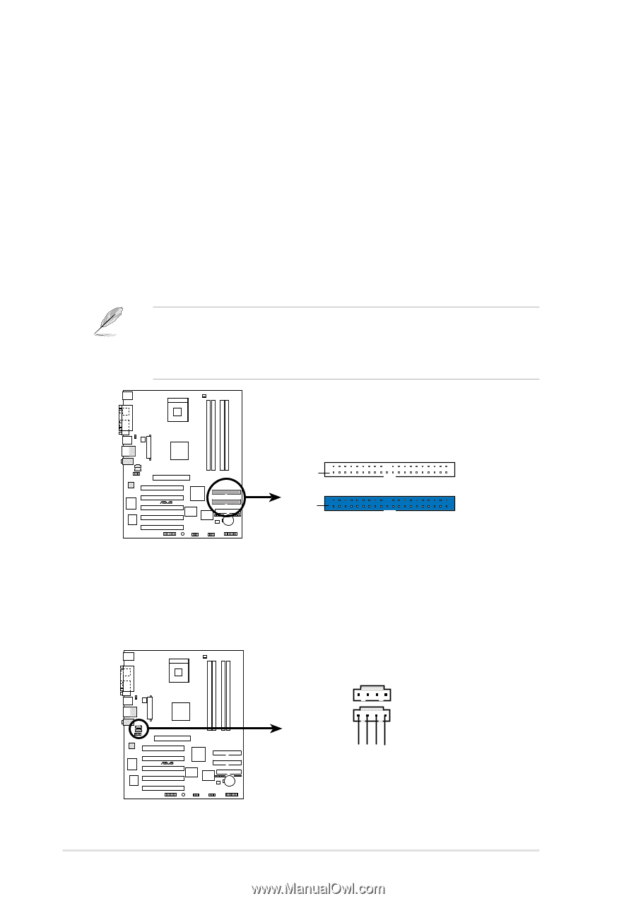
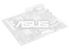
3. IDE connectors (40-1 pin PRI_IDE1, SEC_IDE1) This connector supports the provided UltraDMA/100/66 IDE hard disk ribbon cable. Connect the cable's blue connector to the primary (recommended) or secondary IDE connector, then connect the gray connector to the UltraDMA/100/66 slave device (hard disk drive) and the black connector to the UltraDMA/100/66 master device. It is recommended that you connect nonUltraDMA/100/66 devices to the secondary IDE connector. If you install two hard disks, you must configure the second drive as a slave device by setting its jumper accordingly. Refer to the hard disk documentation for the jumper settings. BIOS supports specific device bootup. If you have more than two UltraDMA/100/66 devices, purchase another UltraDMA/100/66 cable. You may configure two hard disks to be both master devices with two ribbon cables - one for the primary IDE connector and another for the secondary IDE connector. 1. Pin 20 on each IDE connector is removed to match the covered hole on the UltraDMA cable connector. This prevents incorrect orientation when you connect the cables. 2. The hole near the blue connector on the UltraDMA/100/66 cable is intentional. ® P4XP-X P4XP-X IDE Connectors PIN 1 SEC_IDE1 PIN 1 PRI_IDE1 NOTE: Orient the red markings on the IDE ribbon cable to PIN 1 4. Internal audio connectors (4-pin CD1, AUX1) (on audio models only) These connectors allow you to receive stereo audio input from sound sources such as a CD-ROM, TV tuner, or MPEG card. AUX1 (White) CD1 (Black) Left Audio Channel Ground Ground Right Audio Channel ® P4XP-X P4XP-X Internal Audio Connectors 1-16 Chapter 1: Product introduction
-
 1
1 -
2
-
3
-
4
-
5
-
6
-
7
-
8
-
9
-
10
-
11
-
12
-
13
-
14
-
15
-
16
-
17
-
18
-
19
-
20
-
 21
21 -
 22
22 -
 23
23 -
 24
24 -
 25
25 -
 26
26 -
 27
27 -
 28
28 -
 29
29 -
 30
30 -
 31
31 -
32
-
33
-
34
-
35
-
36
-
37
-
38
-
39
-
40
-
41
-
42
-
43
-
44
-
45
-
46
-
47
-
48
-
49
-
50
-
51
-
52
-
53
-
54
-
55
-
56
-
57
-
58
-
59
-
60
-
61
-
62
-
63
-
64
 |
 |